Transcription
Mars 2020 maxon Commercial Motor Development from Commercial-Off-the-Shelfto Flight-Qualified Motors, Gearboxes, and Detent Brakes: Overcoming Issuesand Lessons LearnedMichael LoSchiavo *, Robin Phillips **, Rebecca Mikhaylov* and Lynn Braunschweig**AbstractBuilding on previous collaborations, maxon and the Jet Propulsion Laboratory (JPL) established apartnership to modify Ø20-mm & Ø32-mm Commercial-Off-The-Shelf (COTS) BrushLess Direct Current(BLDC) flat motors and a Ø22-mm planetary gearbox. The commercial design was modified to meet therequirements for the Mars 2020 rover, a Class B [1] interplanetary mission operating in the Martian surfaceenvironment, while maintaining as much of the industrial heritage as possible. Numerous issuesencountered during development were successfully addressed, and qualification of the design andacceptance testing for the 10 Flight Model (FM) actuators installed on the Mars 2020 rover was completedon time for the rover assembly schedule.Mars 2020 Overview and Previous Missionsmaxon brushed motors have significant flight heritage on JPL Mars missions. The Mars PathfinderSojourner rover contained 11 brushed direct current (DC) motors based on the RE16 design [2]. The MarsExploration Rovers (MER), Spirit and Opportunity, each utilized 39 maxon brushed DC motors, based onmodified commercial “RE” series designs. At the end of the Opportunity rover’s mission, all of the drivewheel motors were still functioning, having survived 5111 Sols (Martian day/night thermal cycles), with eachmotor completing 9 107 revolutions. Spare MER motors (4 RE20 and 5 RE25) were also used as partof the Phoenix lander. maxon has continued to develop brushed motors for the Martian applications InteriorExploration using Seismic Investigations, Geodesy and Heat Transport (Insight) mission and ExoMarsmission by modifying newer commercial designs, however, these designs were not viable options for Mars2020 due to the brush sensitivity to a pyroshock environment.Mars 2020 is the first step in a potential multimission approach to a Mars Sample Return mission and futurehuman exploration of Mars [3,4]. The primary objective of the Mars Science Laboratory (MSL) and itsCuriosity rover is to search for habitablity. Mars 2020 [5] and its Perseverance rover will seek signs of pastlife and collect Martian cores for possible later collection and return to Earth. The Mars 2020 projectmaximized the use of build-to-print hardware to reduce development risk and much of the project utilizes alarge amount of spare MSL hardware (specifically the cruise and descent stages). Mars 2020 also levieddesign constraints to remain within the MSL footprint in terms of mass, volume, and power on majorcomponents, such as the rover chassis, which houses the Sample Caching System (SCS), and large roboticarm.The SCS is one of the most advanced robotic systems ever developed for planetary exploration, pushingmore robotic Degrees of Freedom (DOFs) into a smaller volume than has previously been achieved. Withinthe SCS, the Adaptive Caching Assembly (ACA) and Coring Drill [6,7,8,9,10] requires complexmechanisms that need gearmotors smaller in volume than any equivalent hardware developed for MSL.Additionally, solenoid brake channels in the motor controller were traded for additional sensor channels,which required any new motors to utilize a passive holding torque mechanism. Tasked with Mars 2020’smission objective to drill, capture, and store core samples along with volume constraints from the MSL* Jet**Propulsion Laboratory, California Institute of Technology, Pasadena, CAmaxon international ag, Sachseln, SwitzerlandProceedings of the 45th Aerospace Mechanisms Symposium, NASA Johnson Space Center, 2020411
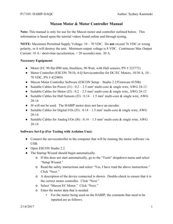
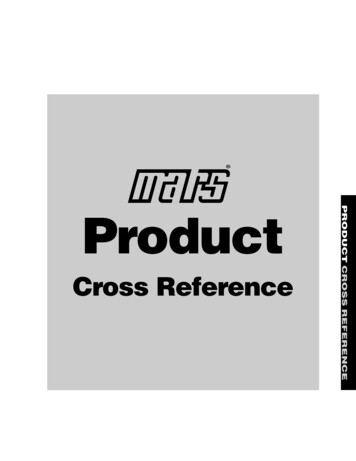
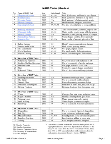
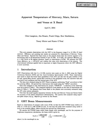
rover, the project required new actuators that then needed to be baselined from proven/existingtechnologies to meet the launch schedule.The Curiosity rover had major actuator development issues, which contributed to the launch slipping from2009 to 2011. The development of several new motors was highlighted as a major reason for the actuatorschedule slips [4,11]. The JPL Mars 2020 actuator team considered the lessons learned from the earlierrover mission and decided to leverage an existing COTS design to reduce the flight hardware schedulerisk.maxon has an extensive catalog of motors for industrial use and has proven flight heritage from the MERmission that, with suitable modifications, the motor designs are robust for space applications. maxon COTSflat motors were utilized in the SCS testbeds and baselined in the original derivation of the system volumeand functional requirements. A close collaboration between maxon and JPL was essential in developing anup-screened COTS-to-robust, flight flat motor mounted on a 2B mission. Two motor types, referred to hereas M20 and M32 (with 20 and 32 being the COTS motor diameter in millimeters), were based on existingmaxon COTS products and chosen to meet the project envelope constraints (Figure 1). The M20 gearmotorincludes an integrated gearbox (Figure 1). Additionally, a detent module was added to the M32 to providea passive holding torque to a static motor. When the motor is spinning above a minimum speed, the inertiais sufficient to overcome any subtractive/additive torques from each detent step, with no significantperformance reduction from the motor.Figure 1. Top Left: M32 motor cut-away showing detent brake; Top Right: M20 FM gearmotor;Bottom: Exploded view of M20 gearmotorMars 2020 Mechanism DescriptionsThe SCS includes a rotary percussive drill located on the turret at the end of the large robotic arm and thesample tube processing plant internal to the rover (the ACA, Figure 2). A 3-DOF arm in the processing plantpasses the tubes and samples to multiple science stations and hermetically seals the tubes. Additionally, abit carousel passes tubes and bits between the internal ACA and the external drill. Several of themechanisms in the SCS subsystem are driven using the M32 detent motors described in this paper, whichare mated to three different torque amplifying planetary gearboxes to provide a family of actuators (named412
SHACD, SAS, and Chuck), designed and manufactured by Sierra Nevada Corporation in Durham, NC. Themotors provide the active driving torque and holding torque for the following applications: the 3-DOF SampleHandling Assembly (SHA), which consists of a linear stage and two rotary (shoulder/elbow) joints; the tubegripper and sealing ram within the tube sealing station of the ACA; the central rotating axis of the bitcarousel; the mechanism that shifts the coring drill between high-speed drilling and high-torque core breakoff modes; and the opening and closing of the chuck at the end of the drill. All of these mechanisms aresingle-string devices performing a serial task in the sequence of capturing a rock core sample.The M20 gearmotor utilized similar modifications as developed in the M32 design effort into the smallermotor diameter for the most volume constrained component of the ACA, the end effector. This componentis mounted to the end of the SHA and physically grabs the sample tube for transport within the ACA.Figure 2. The Adaptive Caching Assembly (ACA)The end effector has some of the strictest planetary protection and handling requirements ever levied on amechanism. The Mars Helicopter technology demonstrator mounts to the underbelly of the rover in itsstowed configuration and has a one-time actuation of the deployment arm. A summary of the four newdesigns utilizing the M20 and M32 motors for 10 flight locations on the rover are listed in Table 1.Table 1. Gearmotor assignmentsGearmotor NameMotorSHA ElbowApplicationSHACDM32SHA LinearSHACDM32SHA ShoulderSHACDM32Bit CarouselSHACDM32Tube Drop-offSHACDM32Sealing StationSASM32Core-Break Lock OutSASM32Helicopter Deployment ArmSASM32ChuckM32DEE (M20)M20ChuckEnd Effector413
Mars 2020 Specific RequirementsThere are several key and driving requirements derived from the Mars environment and missionrequirements:1. The mission objective to look for compounds that provide evidence of life on Mars levied strictContamination Control and Planetary Protection handling, design, and assembly constraints,including: reducing organic materials used for assembly and treating them to minimize outgassingand deposition on crucial components, cleaning all surfaces to prevent contamination frommigrating due to handling, and eliminating/reducing viable compounds from spores and organicmaterials from Earth.2. The actuators located on the extremities of the rover arm are subjected to wide diurnal temperaturechanges, which is highly stressing on electronic components and bonded materials.3. In addition to pyrotechnic release devices, the rotary percussive drill generates an environment thatcan be defined as a combination of a random vibration, sine vibration, and pyroshock. Thisenvironment varies depending on several factors, including the hardness of the rock being drilledinto, the percussion frequency used for drilling, and the weight-on-bit applied. Ref. [7] containsmore information on the coring drill. The dynamic environment fatigues components and canamplify natural modes in hardware, which then couples with fatigue induced from extreme thermalcycling.maxon Catalog Flat Motor and Gearbox Designmaxon has 50 years of experience designing and manufacturing brushed and brushless DC electric motors,gearboxes (both planetary and spur), feedback devices, and control electronics. The brushless DC motorsare offered in several families of types, covering both ironless winding and iron-core winding types. Theiron-core winding types are in turn divided into external and internal rotor families where the rotor mountedpermanent magnets are respectively outside or inside the windings. Both the M20 and M32 motors arederived from maxon’s “flat motor” family (Figure 3),which are of the BLDC external rotor type.Figure 3. maxon flat motor standard featuresFor industrial applications, compared to other BLDCtypes, the flat motors represent a simple, low-costdesign that delivers high torque in a short (but largediameter) envelope. When operated without ahousing in Earth atmosphere conditions, theexposed spinning outer rotor also enables excellentconvective cooling and hence high continuouspower ratings.maxon’s flat motor family covers various diameters (14, 20, 32, 45, 60, and 90 mm), all of which share thesame basic design. A large-diameter rotor provides the structural support and acts as a magnet return fora ring magnet. This rotor is supported by two ball bearings housed in a flange/bearing support structure.The bearings are preloaded by use of a spring. A stator sheet stack is wrapped with magnet wire andmounted to the bearing support structure while being electrically connected to a printed circuit board (PCB),which also holds three Hall sensors that detect the main magnet position.maxon has the industrial heritage for the flat motor design, which has been built several million times,including over 1 million units for commercial truck exhaust gas cleaning systems, an application thatprovides real world proof of the robustness of the basic design.Flight Fidelity Modifications to the Catalog DesignsIt was known from previous maxon work that commercial motor designs usually require some modificationsto allow reliable operation in a Martian environment, in particular, the wide temperature range cycling,414
vibration/shock environment, and vacuum exposure. After determining that the Ø20 mm and Ø32 mmmodels provided the optimal power versus mass compromise, the commercial design was analyzed by ateam incorporating both JPL and maxon personnel with the intention of applying the previous experienceof both organizations to optimize the design for ultimate reliability in the harsh Martian environment. Table 2lists the features in the COTS design that needed modification.Table 2. COTS design and modifications for Martian environmentCOTS DesignDesign Risk for Mars 2020 ApplicationSolutionFlange bearing carrier out of several Connection under shock/vibration; corrosion;parts with dissimilar materialscoefficent of thermal expansion mismatchCreate one-piece flange/bearing carrierStandard Hall sensorsTemperature range limitations, failure due toradiation exposureUse Hall sensor that can be qualified forenvironmental conditionsRotor shaft glued to bearing racesShock and temperature environment breaksadhesive bond and causes rotor to moveAdd securing/spacer rings to design andmount all parts on shaft to hard stop. Weldrotor to shaftMain magnet only partially coveredin adhesiveBond to rotor is not as strong as it could be and Develop new bonding application processmight fail under repeated temperature cyclingto ensure at least 80% coverageFlex-print PCBCan flex under vibration environment, whichleads to mounted components breakingReplace with FR4 and flying lead wireconnectionsWinding taps run directly to PCB 1 cm lengths of unsupported thin wiresusceptible to vibration-induced resonance andbreakageStake winding taps to stator and strainrelief with “expansion loops” next to solderjointIn order for the maxon catalog flat motor to survive the requirements of the Mars 2020 mission, severalchanges were made. The PCB material was changed from a flex print to FR4, a material commonly usedfor space missions as it does not significantly outgas, is robust enough to support the Hall sensors in avibration environment, and fulfills IPC-A-600 Class 3 requirements and testing required by JPL. The bearingpreload architecture was modified so that the entire system was pushed to a hard stop meaning theindividual parts could not shift during impact or vibrations. A more robust spring was selected with shimends to better distribute the forces and prevent the shim from breaching the bearing. High-quality industrialbearings were selected from one of maxon’s standard suppliers. Braycote 600EF was chosen as thelubrication with a fill-factor (15–20%) of the free volume of each bearing measured (by mass) anddocumented.As has been standard practice for decades in space applications, the PCBs in both the M20 and M32designs have conformal coating to: 1) protect the PCB from corrosion while in storage on the groundawaiting launch; 2) protect against short circuits from any debris in weightless conditions; and 3) suppressany tin whisker growth. maxon had a good experience working with Speciality Coating Systems in theCzech Republic for Parylene HT application for ExoMars and chose to work with them again for the Mars2020 motors. The fully populated PCBs, including attached stators with windings were shipped to SpecialityCoating Systems, coated, and returned to maxon for integration into the rest of the motor.Undoubtedly the most difficult component choice to be made when designing a space-rated BLDC motoris the rotor angle detector required for the control electronics to correctly commutate the motor. All ofmaxon’s BLDC motors use various types of Hall sensors for this purpose. As described in Ref. [12], thesolution for ExoMars was a radiation and temperature test program with many different types of compactHall sensors. Unfortunately, the Infinion TLE4945 sensor that was selected for ExoMars has beendiscontinued, but maxon had already tested and selected a variant of Honeywell’s bipolar SS41 Hall sensorrange for other space applications. JPL organized the purchase of a flight batch of sensors that weresubjected to additional screening (pre-conditioning, lead tinning, and thermal cycling as well as lotqualification including Destructive Physical Analysis) to qualify the sensor lot prior to delivery to maxon forpopulation onto the PCBs. These sensors have been shown to operate well outside their published range,although performance deteriorates at the temperature extremes. Satisfactory operation can be achieved415
between -100 C and 200 C. Radiation testing showed no failures after exposure to γ-radiation (absorbeddoses of 300 J/kg for 64h).maxon’s flight heritage from the MER mission does not include gearboxes, however, maxon gainedconsiderable experience during the ExoMars development [13] and qualification program. The programdemonstrated that although COTS planetary gearboxes, in particular those developed for high-temperature“downhole” oil and gas industry applications, can be easily modified for space applications, significantlifetime problems arise when switching to vacuum-rated lubricants such as Braycote 601EF. ExoMarsdevelopment work had shown that using a slurry of grease and oil as previously described for HarmonicDrive applications [14] partially mitigated this lubricant issue. The root cause of the lifetime issues is thatBraycote 601EF is fundamentally unsuitable for lubricating sliding (as opposed to rolling) surfaces. In orderto achieve the lifetime requirements for the ExoMars drill drive, the COTS design sliding motion betweeneach planetary gear and its shaft/axis was converted to rolling motion by the addition of needle bearings,which was then used as the basis for the Mars 2020 gearbox (Figure 4).Figure 4. Exploded view of M20 planetary gearbox stageGiven the mission-critical nature of the M20 application, the JPL and maxon review teams decided thatexcessive residual risk remained in connections between sun gears and planetary carriers as well asbetween the planet axes pins and the carriers. In the COTS design, these connections are press fitted andwelded, however, due to the hardened nature of the materials used for the axes and sun gears, the weldsalways exhibited surface cracks. This is an accepted compromise for industrial applications (and is notknown to have ever caused a field failure), but due to the extreme Martian diurnal temperature cycling, thiswas considered to present an unacceptable risk of weld failure followed by axial movement of thecomponents. The sun gear and planetary carriers’ connection was easily solved by combined these into aone-piece part (by using shaping manufacturing techniques). The problem of how to secure the axes wassolved by adding a cage to the design. Both the cage and the planetary carrier have blind (vented) holesthat the axes are pressed into, without requiring any further retaining mechanism. The cage is pressed ontoan axial hard stop on the planetary carrier and is then cold formed (swaged) into position. The resultantdesign is then both weld- and adhesive-free and enables a free choice of gear and axes materials andhardening processes.No part involved more complexity to manufacture than the combined ring gear and motor flange for theM20 gearmotor. For industrial products, gearbox ring gears and motor flanges are usually screwed togetheron a large diameter thread and then either glued or welded. In the case of the M20, however, the gearmotorneeds to fit inside a ring of springs, which requires a star shape pattern of wires to be precisely orientedrelative to the mounting lugs on the front of the gearbox. The disadvantage of the standard assemblymethod is that the large diameter thread does not allow a precise angular orientation of the gearbox to themotor. The solution to this problem was to combine the flange and the ring gear into one piece. This had416
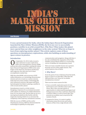
the additional advantage of allowing shorter and lower mass assembly and also eliminated any unreliabilityin the connection. The decision required a significant reordering of the assembly sequence, but this did notcause any further problems. The manufacturing of the part itself, performed within maxon, involved anumber of challenges to address, in particular the deburring of the bottom of the ring gear teeth aftershaping, which required an external supplier for an electrochemical machining step and another externalsupplier for sand blasting the many detailed features on the motor flange.Flight Design Issues InvestigatedDetent DesignTwo versions of the M32 motor were designed, with different detent strengths, each sharing componentsexcept for the magnets generating the field. The axially charged magnet in the two designs had differentlengths, creating a 10 mN m detent and a 20 mN m detent, with the larger length baselined to enable thesame housing to be used for both motor types. The step size of 24 detents per revolution was chosen tocorrespond to the total commutation state changes of the motor design. When paired with a gearbox, thedetent size produces holding torque at a small angle at the gearmotor output.The Hall sensors measure the edge field of the 4-pole pair continuous ring NdFeB magnet. The Hall sensorsare on the output side of the motor for maxon’s flat series designs, which is the same side as the detentmechanism module. When the detent was added to the motor, the performance of the detent mechanismdid not match the strength of the standalone unit and motor switching error was encountered. Measurementof the magnetic field revealed the single axial magnet had significant stray flux in the vicinity of the Hallsensor, causing the switching error and reduced detent strength (Figure 5).Figure 5. Left: Compensation magnet measurements for stray flux; Right: Computed Tomography (CT)scan cross section of final assemblyTwo corrections were made. First, a compensation magnet axially charged in the opposite direction wasadded to the detent magnet stack, strengthening the field through the detent wheel. Second, the axial gapbetween the edge of the rotor cap ring magnet and the Hall sensor was reduced by shimming each motorindividually after measuring subassembly dimensions. The change in axial gap increased the magnetic fieldstrength and hence the signal-to-noise ratio in the Hall sensor.417
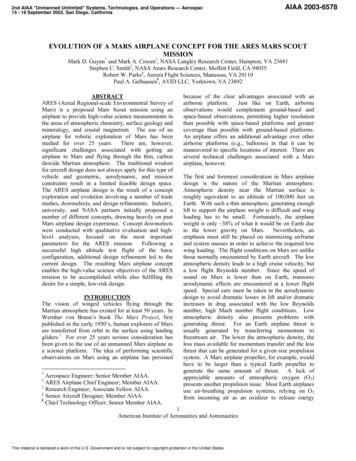
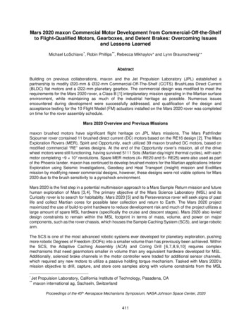
Low-Quantity Grease DosingFor the M20 gearmotor, JPL required rapid acceleration to the commanded speed without an excessivecurrent draw over the entire specified temperature range. This is a problem due to the high viscosity ofBraycote at low temperatures. The standard quantities of grease used per gearbox stage by maxon forCOTS products are determined by the requirement to deliver the longest possible lifetime with standardenvironmental conditions. The use of Braycote required the standard quantities to be reassessed. A seriesof tests were performed with gearboxes built using differing quantities of grease. In each case, highfrequency resolution data of the start-up current draw was collected. It was necessary to reduce the greaseload by a factor of 10 compared to the standard dose in order to obtain acceptable start-up performance.Subsequent life testing demonstrated that the required life (low compared to industrial applications) couldstill be achieved. For the flight units, application using the grease plating method was used to ensure thelow quantity of grease was uniformly distributed, a process that is unnecessary for industrial applications,where only manual dosing with a syringe at defined locations is sufficient.The mechanism driven by the M20 actuator has a limited linear stroke. The cold drag performance of theactuator had significant transience in the first 5 seconds of motion; this large variation in torque productionwas outside the system-level requirements for controllability. JPL tested three actuators at several lowtemperatures in order to characterize the start-up current as a function of temperature. Figure 6 shows aknee in the drag happening between -30 C and -40 C for this gearbox. The actuator still exhibited marginedtorque production at the -70 C operation temperature limit, but due to controllability and other friction effectsin the mechanism at -70 C, the heater was modified to increase the low-end operating temperature.Figure 6. M20 drag current temperature dependenceShock and Motor BearingsThe M32 motor was tested (along with the mating gearboxes) to withstand a pyroshock environmentsimulated by a tunable beam. The pyroshock spectrum had a peak level at 3,000-g with a knee frequencyat 1,600 Hz. After testing, the motor operated with a significant rattle, a noise equated to that of a coffeegrinder. Although CT scans did not reveal gross damage in the assembly, several other non-destructivetests, including a noise frequency analysis and rotating shaft deflection test, indicated motor bearings asthe damaged component. The frequency analysis had peaks at the motor bearing inner ring frequency thatwould scale with motor speed and the deflection test had a signature reminiscent of dimples in the racewayallowing up to 0.0127 mm of deflection. The motor bearings were disassembled and inspected. The motors’front bearing inner ring, outer ring, and balls were deformed in both directions from the tunable beam test(Figure 7). The back bearing did not have any damage.418
Figure 7. Damaged motor bearings from shock eventThe g-level induced by pyroshock was initially analyzed with respect to the brittle components andsolder/strain relief only, and did not consider the spring/mass system of the bearing/rotor combination. Adesign change between COTS and flight had the front bearing hard mounted in both directions, allowingthe back bearing to float, resulting in the front bearing absorbing all of the energy of the accelerated rotor.The M32 motors are used in multiple locations across the Mars 2020 rover and any changes would causea significant project schedule impact. In most locations, the pyroshock requirement was over specified; thehardware was requalification tested to the new pyroshock requirements. The motor, and subsequentgearmotor tests, all passed the new pyroshock exposure and long rotational life requirements. Thereremained a single location where the motor had exposure to the high pyroshock environment but with ashort rotational life. With the project considering the risk, the solution was to use the damaged motor toqualify a deployable device with high shock and limited motor rotational life. The qualification demonstratedthat the damaged motor could achieve the limited revolutions needed. The flight unit was delivered and themechanism underwent qualification at the next level of assembly. The pyrotechnic deployment wasdemonstrated four times and did not produce a “coffee-grinder” motor, showing that the either therequirement or tunable beam test was over conservative. In both solution cases, no changes to the flightmotor were made.Overheating ConcernThe coil-to-coil resistance for the M32 and M20 motors are 14 ohms and 28 ohms, respectively. Additionally,the copper wire is wound around two PEEK stator caps at each end of the stator lamination stack, whichprovides thermal isolation from the bulk stator mass. The current driving the motor causes significant Jouleheating due to the high resistance, quickly increasing the temperature of the low mass of copper wireinsulated from the stator, which can lead to thermal runaway. The overheating worsens as the currentreaches 1A.Due to design principle requirements to demonstrate 2 torque at operational temperature limits, hotdynamometer tests are the highest risk activities to perform on the ground. The M32 has an additionalthermal risk due to the detent mechanism; the larger holding torque design was roughly equal to the nominalperformance of the motor, so twice as much current is needed during slow speeds (where the rotor has nosignifcant inertia to carry it over the detent peaks) compared to fast speeds. A thermally instrumented unitwas used to create a thermal model to understand this interaction. Guidelines for operation early on in theMars 2020 design and qualification program were related to current input and time—a current profile couldbe estimated, the heat input was analyzed to confirm no overheat condition was achieved, and then a waitperiod was enforced in order to ensure the test article reached steady state.419
The mechanism testing and subsequent system-level testing had sequences and current profiles that couldnot be predicted. The solution was to use a simplified thermal model on both the rover and control electricalground support equipment (EGSE), which was the same implementation used on the MER rovers. Themodel is supplied with a case temperature from a platinum resistance thermometer (PRT) and the currenttelemetry feeds the Joule heating. The thermal protection watches for nodes and can shut down motion iftemperatures rise above certain limits.Acceptance and Qualification TestingAn acceptance test program was implemented to determine JPL acceptability of the M32 and M20 motors.The acceptance testing centered on workmanship and functional performance of each unit, whereas aqualification program subjects designated units to the gambit of JPL-margined dynamic and thermalenvironments and life tests to verify that the design of units from the same production and manufacturinglots would meet the mission requirements. Qualification was completed at the gearmotor level, with someactuators further qualified at the mechanism level. Portions of the M20 gearmotor qualification testing werecompleted at maxon using their testing facilities, where feasible. The residual tests were completed at JPLdue to infrastructure availability as well as long-duration (life test) activities outside of the scope of maxon’scontractual effort.All M32 FM units were subjected to the acceptance tests listed in Table 3, with defined criteria whenappropriate. No-load characterization was used as a functional check to confirm the specific motor wasperforming as expected and within family for the M32 flight motors.Table 3. M32 motor acceptance testsM32 Motor Acceptance TestDielectric strengthInsulation resistance (R)Test ConditionsI 1 mA500V DC, for 60 5 secondsR 100 MΩN/AR (flange to housing) 25 mΩR (flange to shaft) 100ΩElectrical bondingRun-inAcceptance Criteria500V AC, 60 Hz for 60 5 seconds60 seconds CW and 60 seconds CCW at 28VN/AHall effect Integrated NonLinearity (INL) sensorMaxon defined test 10 INL (target 7.5
The Mars Pathfinder JPL Sojourner rover contained 11 brushed direct current ( DC) motors based on the RE16 design [2]. The Mars Exploration Rovers (MER), Spirit and Opportunity, each utilized 39 maxon brushed DC motors, based on modified commercial "RE" series designs. At the end of the Opportunity rover's mission, all of the drive