Transcription
Cummins ISL-GWebinar
ModeratorJerry GuaracinoDeputy Chief Engineering OfficerSoutheastern Pennsylvania Transportation Authority (SEPTA)Philadelphia, PA
PresentersObed MejiaVictoria ChesneySenior Bus Equipment Maintenance InstructorLos Angeles Metropolitan Transportation AuthorityLos Angeles, CAMaintenance SupervisorOmnitransSan Bernardino, CA
ObjectivesParticipants on today’s webinar will learn how to: Identify Maintenance Procedures Examine components to meet specifications Perform maintenance practices to OEM specifications
Related APTA Standards APTA BTS-BMT-RP-008-16: TrainingSyllabus to Instruct Bus Technicians onEPA Emissions Standards andTreatment TechnologiesFor additional resources Pages/default.aspx
Fleet FactsMetroOmnitrans 2400 Buses in service 2300 ISL-G 100 L Gas Plus 187 Fixed Route Coaches Revenue Miles 90 million per year 22 Cummins 8.3 C 43 8.1 John Deere HFN04 122 8.9 Cummins ISL G Service area of 456 sq. miles withjust over 9 million miles run per year.
Operating Parameters Maximum Horsepower 320 HP Peak Torque 1000 LB-FT Governed Speed 2200 RPM Engine Displacement 540 CU IN 8.9LITERS spark-ignited, in-line 6-cylinder,turbocharged, CAC Fuel Type CNG/LNG/RNG Methanenumber75 or greater Aftertreatment Three-Way Catalyst (TW
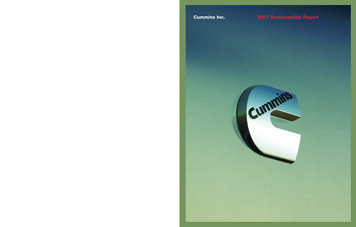
Engine Management System The control system for the ISL-G engineis a closed loop control system. Theelectronic control module controls thethrottle plate and fuel control valve toprovide the correct fueling and sparktiming. The ISL-G engine through the years hasbeen built with several potential sensorconfigurations and terminologyvariances. Ensure that you are using the latestsoftware version to correctly interactwith control system.
Control System Components
Control System Components
Ignition SystemCapacitive dischargesystem. The ICM (Ignition ControlModule) steps 12V inputand steps up to 250-300Vto the primary side of thecoil.
CNG Fuel Flow - Sample
EGR System The EGR system is responsible for recirculating metered exhaust gas backinto the combustion chamber. This is done to cool down thechamber temperature byintroducing inert gas. Nitric Oxides emissions areformed when engine chambertemperatures rise above 2500 F.Keeping the chamber coolreduces NOx emission. System Components: EGR valve,cooler, flow and temperaturesensors.
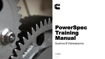
EGR Cooler The cooler cools the exhaust gasbefore it’s recirculated into theintake manifold. This assist inreducing the combustionchamber temperature. The cooler circulates enginecoolant through the EGR as aheat exchange medium. Currently there are two styles inuse. Horizontal Plate – square style(illustration 1) Circular style (illustration 2)12
MaintenanceProcedures
Spark Plug R&R ProcedureRemoval: Do not wiggle coil brackets when removing coils– remove straight up Remove spark plug with a magnetic socket Blow-Out Spark Plug cavity
Spark Plug R&R ProcedureInstallation: Check Plug Gap – do not adjust/donot install if out of gap Prior to installation spark plug mustbe cleaned with alcohol pad orswab. Dirt, oil, and fingerprintsreduce the seal strength betweenthe spark plug boot and theporcelain causing reduced sparkplug life.
Spark Plug R&R ProcedureInstallation: Remove old boot from coilextension Inspect coil for cracks orevidence of arcing Clean coil extension Install new spark plug boots tocoils, new boots come withdielectric grease from thefactory. If boots do not havedielectric grease, apply a smallamount.
Spark Plug R&R ProcedureInstallation: Install new spark plugs using cleanmagnetic spark plug socket. Torque spark plug to 28 ft-lb (35 Nm). Failure to torque spark plugs will resultin engine misfire and premature sparkplug failure. Proper torque aids in heat dissipation
Acceptable Spark Reuse - CumminsConsult Cummins Quikserve for latest TSB’s
Not-Acceptable Spark Reuse - CumminsConsult Cummins Quikserve for latest TSB’s
Valve Adjustment ProceduresGeneral Knowledge: valve adjustments are a critical part ofthe preventive maintenance and the bus repair process.During the procedure; keep in mind: Engine should be at 140⁰ F or less. Check valve height – valve may recess into head causing performancecomplaints Check the rocker shafts for wear – this may cause the rocker to bind
Valve Adjustment ProcedureOverlap Method:1.Rotate engine until valve overlap is reachedon cylinder #6. Valve overlap is when boththe intake and exhaust valves are openedat the same time. You will notice that asthe exhaust valve is closing the intake valvestarts to open. Valve overlap occurs forabout 15 of crankshaft rotation.
Valve Adjustment ProcedureOverlap Method:2. With valve overlap on #6, cylinder #1will be on TDC. Both intake and exhaust rockers willbe loose indicating valves are closed.3. Make a reference mark on the crankpulley and timing cover in preparationfor next step.
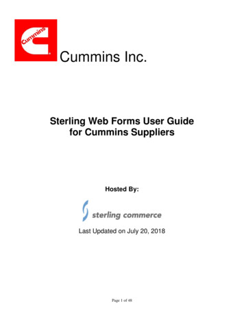
Valve Adjustment ProcedureOverlap Method:4. Adjust valves as shown below.
Valve Adjustment ProcedureAdjustment Specs:Intake: .014 in. Exhaust: .030 in.During the adjustment, keep in mind to: Keep medium drag on the feeler gauge tocomplete adjustment. Tight valves will cause performance issues. Loose valves will cause noise andperformance issues. Recheck lash after tightening adjuster screw.
Valve Adjustment ProcedureOverlap Method:6. After adjusting valves onvalve overlap on cylinder#6, rotate the engine afull revolution 360 . Alignthe previously madereference marks.Cylinder #1 is now inoverlap and cylinder #6at Top Dead Center(TDC).7. Adjust valves 2E 3l,4E,5l, 6l and 6E.
Valve Adjustment Procedure –Rocker Shafts – it is recommended toperform a rocker assembly inspection.(requires removal of rocker assemblies) Remove and mark the pedestals and rockerlever assemblies one at a time. Inspect forcracks and excessive wear on the shafts.Check for scoring and or binding. – replaceassembly if found. The rocker arm shouldmove freely on the rocker shaft. Inspect the rocker lever pedestal androcker lever shaft for cracks.
Valve Adjustment ProcedureReceded Valves:A- Inspect the valve stems for heightvariations. Valves that are sticking outtoo far indicate the valve has recededinto cylinder head.B- Using a straight edge, look for thevalve stems to be NO more than 3/16”higher than others. If valves are foundto be high; replace the cylinder head.Recessed valves cause performanceissues that may include low power anda CEL.
Steel Piston Conversion New piston design for improveddurability In-frame replacement Cummins sells as complete overhaulkit Needs new calibration Needs emissions decal
EGR Cooler Carbon New EGR Cooler longevity isnow showing the typical carbonbuildup of EGR coolers Causes trouble codes for EGRcooler temperature Cummins recommendscleaning the carbon buildup
MaintenanceConcerns
Past Issues EGR Cooler Leaks 3 Generations Aluminum Piston Melting/Cracking Steel Conversion Cummins Quikserve hasdeveloped a picture libraryof damage piston andpossible causes.
Past Issues Ignition Control Module High failure rate – caused misfire codes Susceptible to voltage and groundfluctuations Collateral Damage Turbo, spark plugs, 02 sensor, catalyst
Current Issues EGR Cooler carbon accumulation Coolant Level Sensor – OEM Plastic vs. Steel Harness contamination due tocoolant leakage
Training
Troubleshooting and Diagnostics Insite Quickserve EDS Use as backuptroubleshooting method Work Orders Need technician notesto assist expeditingrepairs
Troubleshooting and Diagnostics Tune-Up Procedures Valve Adjustments Procedures Engine temperature Spark Plug Replacement Cleanliness Proper torque Calibrations De-rate Program Minimize piston damage
Summary
The Future of CNG ISL-G Near Zero Engine L9N Omnitrans will be retrofitting its older coaches All new bus buys will have the near zero installed LA Metro current bus orders will have near zero installed 295 El Dorado Buses LA Metro currently installing as replacement engine during midlife 400 engines on procurement LA Metro moving to 100% Electric Vehicle Fleet The Goal is 2030 Contracts for 100 Electric buses have been awarded
Any Questions?Please e-mail the questions tostandards@apta.comThe APTA Brake and Chassis Work Group andthe APTA Bus Standards Committee would liketo thank you for joining our Webinar.Pictures, drawings and technical information courtesy of MAN, ZF, Meritor, Knorr-Bremse, Bendix, MGM Brakes, LA Metro,Omnitrans, MBTA, Custom Training Aids, Link Engineering, and other members of the APTA Brake and Chassis Work Group42
electronic control module controls the throttle plate and fuel control valve to provide the correct fueling and spark timing. The ISL-G engine through the years has been built with several potential sensor configurations and terminology variances. Ensure that you are using the latest software version to correctly interact with control .