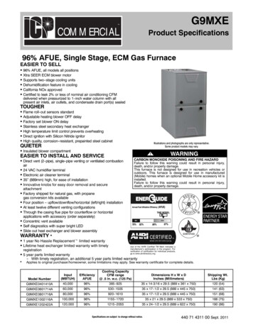
Transcription
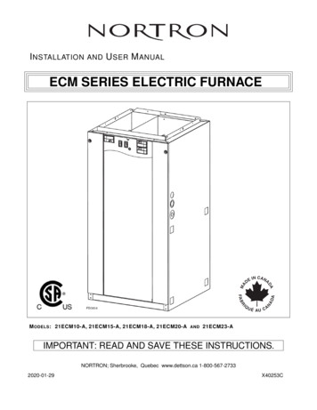
I NSTALLATIONANDU SER M ANUALECM SERIES ELECTRIC FURNACEM ODELS : 21ECM10-A, 21ECM15-A, 21ECM18-A, 21ECM20-A AND 21ECM23-AIMPORTANT: READ AND SAVE THESE INSTRUCTIONS.NORTRON; Sherbrooke, Quebec www.dettson.ca 1-800-567-27332020-01-29X40253C
WARNING Never tamper with the unit or its controls. User MUST contact aspecialized contractor when a failure occurs. DO NOT ATTEMPTto repair. When using a humidifier make sure not to damage the heatingelement bank. Poor maintenance of air filters OR an unbalanced static pressuremay result in a performance decrease. Always use genuine parts for maintenance or service call. Theuse of unbranded parts will void the warranty. The use of this unitwithout an air distribution duct will void the warranty. It is strictly forbidden to use jumpers to simulate heat demand. Risk of electrical shock. Disconnect power before installation,servicing, maintenance or field wiring. Replace all panels beforeoperating. Failure to do so can result in electrical shock causingsevere injuries or death. When performing installation, servicing or cleaning the unit, it isrecommended to wear safety glasses and gloves. To assure a proper performance of your furnace, we recommendthat you use high quality name brand thermostats. When applicable local regulation comprises more restrictiveinstallation and/or certification requirements, the aforementionedrequirements prevail on those of this document and the installeragrees to conform to these at his own expense. For your safety, do not store or use gasoline or other flammableliquids and vapors in the vicinity of this unit or any other appliance. These instructions are intended to be used by qualified personnelwho have been trained in installing this type of furnace.Installation of this furnace by an unqualified person may lead toequipment damage and/or hazardous condition which may leadto bodily harm. This furnace is not watertight and is not designed for outdoorinstallation. This furnace shall be installed in such a manneras to protect its electrical components from water. Outdoorinstallation leads to a hazardous electrical condition and topremature furnace failure, thus voiding the warranty. Do not block the combustion air openings in the furnace. Anyblockage will result in improper overheat situation and may resultin a fire hazard and/or cause bodily harm. The unit must have an uninterrupted or unbroken electricalground to minimize personal injury if an electrical fault shouldoccur. When performing electrical connection, the groundconductor must be firmly attached to the ground lug in thefurnace. Do not use this furnace as a construction heater. Use ofthis furnace as a construction heater exposes the furnace toabnormal conditions, contaminated combustion air and the lackof air filters. Failure to follow this warning can lead to prematurefurnace failure and/or vent failure which could result in a firehazard and/or bodily harm. The owner and/or the user is responsible of the following:Always maintain the immediate surrounding of the furnace freefrom combustible and highly flammables materials.The furnaceambient air should not have an excessive dust concentration andhumidity. Never operate this central heating appliance without anair filter. Before performing any service functions, unless operationsspecifically require the power to be on, make sure all utilities areturned “OFF” upstream of the appliance. Failure to comply withthis warning will cause a fire hazard and/or bodily harm. All questions regarding the operation, maintenance or warranty ofthis unit should be addressed to the company where this producthas been sold from.CAUTION Never burn garbage or paper in the heating system and never leave rags or paper around the unit. Return air grilles and warm air registers must not be obstructed.IMPORTANT: All local and national code requirements governing the electrical installation heating equipment, wiring andflue connections must be followed. Some of the codes that may be applicable are :ANSI/NFPA 70 NATIONAL ELECTRICAL CODECSA C22.1 CANADIAN ELECTRICAL CODEOnly the latest issues of the above codes should be used, and are available from either:The National Fire Protection AgencyBatterymarch ParkQuincy, MA 02269or2The Canadian Standards Association178 Rexdale Blvd.Rexdale, Ontario M9W 1R3
Table of Content1Dimensions . . . . . . . . . . . . . . . . . . . . . . . . . . . . . . . . . . . . . . . . . . . . . . . . . . . . . . .32General Requirements and Specifications. . . . . . . . . . . . . . . . . . . . . . . . . . . . . . . . . . . .43Operating Options . . . . . . . . . . . . . . . . . . . . . . . . . . . . . . . . . . . . . . . . . . . . . . . . . . .54Breakers55Installation Notes. . . . . . . . . . . . . . . . . . . . . . . . . . . . . . . . . . . . . . . . . . . . . . . . . . . . . . . . . . . . . . . . . . . . . . . . . . . . . . . . . . . . . . . . . . . . . . . . . . . . . . . . . .65.1 Cold Air Return . . . . . . . . . . . . . . . . . . . . . . . . . . . . . . . . . . . . . . . . . . . . . . . . . . . . . . . . . . . . . . . . . .65.2 Electrica Wiring - Power Supply . . . . . . . . . . . . . . . . . . . . . . . . . . . . . . . . . . . . . . . . . . . . . . . . . . . . . . .65.3 Connecting and Adjusting the Low Voltage Thermostat . . . . . . . . . . . . . . . . . . . . . . . . . . . . . . . . . . . . . .66Use in Mobile Homes . . . . . . . . . . . . . . . . . . . . . . . . . . . . . . . . . . . . . . . . . . . . . . . . .77Using Optional Equipment . . . . . . . . . . . . . . . . . . . . . . . . . . . . . . . . . . . . . . . . . . . . . .77.1 Two-Stage or Outdoor Thermostat . . . . . . . . . . . . . . . . . . . . . . . . . . . . . . . . . . . . . . . . . . . . . . . . . . . . .77.2 Air Conditioning . . . . . . . . . . . . . . . . . . . . . . . . . . . . . . . . . . . . . . . . . . . . . . . . . . . . . . . . . . . . . . . . . .77.3 Electronic Air Cleaners and/or Powered Furnace Humidifiers . . . . . . . . . . . . . . . . . . . . . . . . . . . . . . . . .87.4 Interlock Conection . . . . . . . . . . . . . . . . . . . . . . . . . . . . . . . . . . . . . . . . . . . . . . . . . . . . . . . . . . . . . . . .88Wiring Diagrams . . . . . . . . . . . . . . . . . . . . . . . . . . . . . . . . . . . . . . . . . . . . . . . . . . . .99Service Parts . . . . . . . . . . . . . . . . . . . . . . . . . . . . . . . . . . . . . . . . . . . . . . . . . . . . . .1010 Maintenance . . . . . . . . . . . . . . . . . . . . . . . . . . . . . . . . . . . . . . . . . . . . . . . . . . . . . .1111 Troubleshooting . . . . . . . . . . . . . . . . . . . . . . . . . . . . . . . . . . . . . . . . . . . . . . . . . . . .1112 Warranty121. . . . . . . . . . . . . . . . . . . . . . . . . . . . . . . . . . . . . . . . . . . . . . . . . . . . . . . .Dimensions3
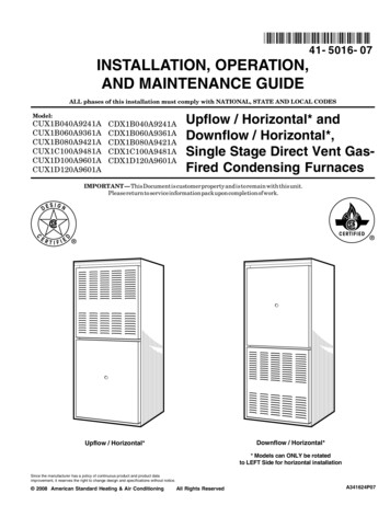
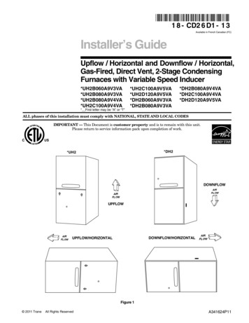
2General Requirements and SpecificationsCAUTIONThis unit must be installed in a dry place, in a non-corrosive, well-ventilated environment, without excessive dust.The ambient temperatue must be over 10 C and under 27 C. If the ambient temperatue is 10 C or less, the plenummust be insulated on 10 ft linear minimum length.1. LOCATION – The furnace should be centrally located to the heating area.2. POSITIONS – It can be installed for vertical, horizontal or downflow operation. When installed horizontally, thefurnace should be positioned such as the door will not end up being on the top. The door should be on the side ofthe furnace, to ensure that the motor bearings are in their designed position. In vertical downflow installations, useonly “L”- or “T”-shaped plenum with no openings or registers directly below furnace.3. INSTALLATION CLEARANCES – As shipped from the factory, each unit is approved for “zero inch” clearance. Ifadditional clearance is required, it will be indicated on the data label attached to the furnace.4. TEMPERATURE RISE – Furnaces are shipped to operate at 0.20” W.C. (50 Pa) external static pressure. They arecertified for operation up to 0.50” W.C. (125 Pa). Check below for temperature rise table on specification chart and,if necessary, adjust the unit to match.5. SERVICE CLEARANCE – Units are serviced from the FRONT. Leave at least 24” (610 mm) clearance in front ofthe door.240 VOLTS - SINGLE PHASEMODEL S INCL. CFML/sSUGG. BREAKER SIZE (A)60100100125125HP1/31/31/31/31/3TEMPERATURE RISE@ 0.20" W.C. C FSPEED*24 42LOW25 46MED30 55MED34 60MED39 70MEDSTATIC PRESSURE(INCHES OF WATER 4110409959459008604914704464254061130 1095 1045 1015 965533517493479455WARNING:* FACTORY SETTINGS.** These models must NOT be setup to run continuously at LOW speed as it will cause overheating conditions. Thesemodels are certified to run only at HIGH and MED speeds.SPECIFICATIONS SUBJECT TO CHANGE WITHOUT NOTICE4
3Operating OptionsThe furnace is shipped from the factory in a “Standard Heating Mode” (all switches are in the Down position). When the thermostatcalls for heat, the automatic controls will be activated and the furnace turned “ON”.The blower will run at low speed or higher speed (as selected by SPEED SELECTOR switch).As the furnace heats up, it automatically switches to the pre-programmed heating speed when additional elements are activated bythe electronic control, if it was initially set to run at low speed. The timing of this blower speed change will depend on whether C OLDor M ILD is selected on the SEASON SELECT switch.You may, however, change from the Standard Heating Mode by using the controls built into your furnace.The SPEED SELECTOR switch is used to control the fan speed(ventilation). Even if there is no call for heat, the ventilation canbe controlled by the thermostat; the fan speed is determined bythis switch.During spring and fall, you may not require full heating capacityto maintain a comfortable temperature.H IGH – The blower motor will operate at low speed.M ILD – Approximately half of the elements are “off-line” and willnot be energized when the thermostat calls for heat.L OW – The blower motor will operate at a higher speed.C OLD – All elements are “on-line” and controlled by thethermostat.NOTE: If outdoor or two-stage thermostat is used, switch MUSTbe in MILD position at all times. This switch has no effect on the10 kW model.4BreakersECM Series furnaces are equipped with breakers, located onthe front panel of the unit. These devices protect the heatingelements from overcurrent. If this situation occurs, the breakerswill open to cut the power from the heating elements only.NOTE: The number of breakers varies according to thefurnace model; 21ECM10 model has no breakers, 21ECM15,21ECM18 and 21ECM20 models have 2 breakers, and21ECM23 and 21ECM25 models have 3 breakers. Refer toSection 8 Wiring Diagrams.WARNINGBreakers do not cut power to entire furnace, only to the heating elements. Do not use the breakers to turn off the furnace. Thepower to the whole unit can only be cut from the main electrical panel.5
5Installation Notes5.1Cold Air ReturnThe duct can be attached to either side, rear or the bottom of the furnace.For side return there are four 1½” (38 mm) knockouts which can be removed and used as an outline for cutting a 18” x 18” (457 mm x457 mm) return air opening in the furnace left or right side. Mount the filter frame to the furnace over the opening with the open sideof the frame facing front. Then attach the 19” x 19” (483 mm x 483 mm) air duct to the flanges on the filter frame.For bottom mounting, remove the screws holding the bottom plate to the furnace, discard the bottom plate and attach the filter frameto the bottom flanges with the open side of the frame facing front.5.2Electrica Wiring - Power SupplyThe furnaces are completely factory wired. From a separate breaker, a two-wire plus ground supply wire is required for single phaseunits, and a three-wire plus ground supply wire for three phase units. The ground conductor must be firmly attached to the ground lugin the furnace and the supply wires to the terminal block in the furnace.NOTE: When a FK120 kit is used to supply an air cleaner and/or humidifier, a third (neutral) conductor must be brought into thefurnace.WARNINGFor all installations, we only recommend appropriate gauge good quality copper wire(s). However, it is the electrician’sresponsibility to ensure that the wiring and connections are compliant to the latest editions of the Canadian Electrical Codeand local codes.5.3Connecting and Adjusting the Low Voltage ThermostatUse only class 1 wires inside furnace compartments.Attach thermostat wires to the low voltage terminal block located on the inside of the furnace. Follow the diagrams supplied with thethermostat. As a general guide, remember that the R & W terminals control single stage heating; the R & Y terminals control cooling.Single stage cooling uses “Y/Y2” as first and only stage.Two-stage cooling uses “Y1” as first stage and “Y/Y2” as second stage. Makesure the thermostat is levelled on the wall and in appropriate location as per instructions supplied with the thermostat.CAUTIONBefore turning the furnace on, the heat anticipator in the thermostat must be properly set.Because each installation is different an accurate reading of the current draw should be made with an AC meter. Set the meter at 2 Arange for furnaces through 20 kW, and at 4 A range for larger units.A Set the anticipator at its highest setting.B Disconnect the “W1” thermostat wire from the furnace low voltage terminal connections.C Connect the AC meter between the “W1” terminal on the board and the loose “W1” wire.D Turn the thermostat up to start the furnace and allow it to run,with all elements on, for three or four minutes.E Read the current draw on the meter and reset the anticipator to match the meter reading.6
6Use in Mobile HomesSHALLOW DUCT AREA REQUIREMENTSModels from 10 kW to 20 kW are certified for “L”-shape and “T”shape shallow duct installation with model FSB-1 sub-base indownflow applications when the supply air ducts pass throughthe floor of the structure. Recommended size of a floor opening:14¼” x 14¼” (362 mm x 362 mm). The duct system must bedesigned so that the external static pressure of the system doesnot exceed the maximum external static pressure of 0.50” W.C.(125 Pa).77.1D UCT D EPTHD UCT W IDTH4" (102 mm)16" (406 mm)5" (127 mm)13" (330 mm)6" (152 mm)10" (254 mm)Using Optional EquipmentTwo-Stage or Outdoor ThermostatThe SEASON SELECT switch must be in the M ILD position.ModelFirst StageThese controls can be used on all furnaces except 10 kWmodel.10 kW10 kW–15 kW10 kW5 kW18 kW9 kW9 kW20 kW10 kW10 kW25 kW15 kW10 kWFollow the directions supplied with the two-stage or outdoorthermostat in conjunction with the furnace wiring diagram.When used, the furnace stage will supply heat as follows inthe opposite chart:7.2Second StageAir ConditioningYour furnace is equipped with all the controls required for theaddition of air conditioning (except the heat-cool thermostat).The evaporator coil may be installed by a local contractor insheet metal plenum of his own manufacture. The coil should belocated: centred over the “chimney” of the furnace 4” (102 mm)to 6” (152 mm) above the top of the furnace.Make sure no air is allowed to bypass the cooling coil duringcooling operation. If the discharge opening is a great deal largerthan the coil, and the ductwork is correspondingly larger thanthe coil, you may want to use a bypass damper for heating.The damper would be closed in summer, directing all air flowthrough the coil. In winter the damper would be open to allowair to bypass the coil.WIRING COLOR CODECGRW1W2YCOMMON GREEN RED WHITE WHITE (BLUE) YELLOWTypical air-conditioning field wiring connections are shown inthe diagram at right.7
7.3Electronic Air Cleaners and/or Powered Furnace HumidifiersThese units operate at 120 V. Your 240 V furnace is designed so that Model FK120 adaptor kit can be mounted inside the furnace tosupply the required 120 V. Instructions for mounting and wiring are included with the kit.7.4Interlock ConectionWhen the electric furnace is used in combination with anotherdevice (as for example, a wood burning furnace), it isrecommended to perform the connection by referring to thewiring diagram at right. The burning furnace thermostat willthen turn automatically on the blower in the electric furnace.Also, please note that Norton has developped a low speedinterlock kit; the FIK (Furnace Interlock Kit). This kit is speciallydesigned to interlock the furnace operation with a ventilation fanor an HRV unit.8
8Wiring DiagramsWARNINGRisk of electric shock. Disconnect power before installation, servicing, maintenance or field wiring. Replace all panels beforeoperating. Failure to do so can result in electric shock causing severe injuries or death.9
9Service PartsIn order to ensure your unit remains in good working condition, you must use Nortron genuine replacement parts only. The Nortron genuine replacement parts are speciallydesigned for each unit and are manufactured to comply with all the applicable certification standards and maintain a high standard of safety. Any third party replacementpart used may cause serious damage and drastically reduce the performance level of your unit, which will result in premature failing. Also, Nortron recommends to contacta certified service depot for all replacement parts and repairs.No.123456789101112Part No.DescriptionL01H030 24VDC Relay (DPST)30274131 24VDC Relay (SPDT)30300022 TransformerZ01I035 Blower 8 x 12B40805-04 Motor (10 KW)B40805-05 Motor (15-18 KW)B40805-06 Motor (20-23 KW)B43015-01 Blower assembly (10 KW)B43015-03 Blower assembly (15-18 KW)B43015-04 Blower assembly (20-23 KW)B04351-01 Element 4kW 240VB04351-02 Element 5kW 240VNo.131415161718192021-10Part No.DescriptionL99F007 Terminal block624665 Electronic controlL01H009 24VAC Relay (SPDT)R02N028 Automatic limitL07F015 SwitchL01J006 Breaker30010010 Filter 20 x 20 x 1B43004-05 Service door (2 breakers)B43004-06 Service door (3 breakers)FIKFK120Furnace interlock kit (separate)120V kit (separate)
10MaintenanceMOTOR: The motor is lubricated for life and needs no oiling.FILTERS: Size is 20” x 20” x 1” (508 mm x 508 mm x 25 mm). Should be inspected and replaced when dirty. Ordinarily replacementis required twice per heating season and, perhaps, a third time if continuous blower operation is used.NOTE: The elements have an automatic reset thermal cut-out which is set to open at 100 F (38 C). If it opens, the elements will bede-energized until the cut-out resets itself.WARNINGCut 240 V power supply before removing the front panel!11TroubleshootingThe first step in identifying an operational problem is todetermine whether the fault is in the furnace or in the thermostatand/or its connecting wiring.2. If the furnace will not turn off:Turn the thermostat to its lowest setting. If there is no more 24Vbetween terminals C and W and the furnace continues to run,the thermostat has opened properly and the problem residesin the furnace. Otherwise, the fault is in the thermostat or itsconnecting wiring. After the fault area is isolated by use of thethermostat, a check of the following components can be mademore efficiently:1. If the furnace will not start:Turn the thermostat to its highest setting. If 24V is presentbetween terminals C and W, the thermostat has closed, sothe fault is in the furnace. Otherwise, the thermosat or itsconnecting wiring is the problem.Problem1. The furnace will not turn on.2. Motor runs continuously.3. Elements on, but motor does not run.-Possible defective parts or componentsThermostatCircuit breaker or fuse is openMotor or capacitorSPEED SELECTOR switch (open contact)Electronic controlTransformerThermostat wires incorrectly attached to the furnaceMotor or capacitorSPEED SELECTOR switch (open contact)Electronic controlHeat anticipator in thermostat incorrectly set or may be defective4. Motor going on and off in short cycles(or in too long cycles).5. The thermostat must be set much higher (or lower) - The thermostat is not leveled or out of calibrationthan the desired house temperature.6. Not enough heat.- Elements or relays- SEASON SELECT switch set in MILD position- Safety limits opening because duct obstruction or dirty filters are restricting air flow- Defective or incorrectly wired two-stage or outdoor thermostat- Lack of enough cold air returns in house7. Two-stage or outdoor thermostat not operating- SEASON SELECT switch not set in MILD positionproperly.8. Breaker on front panel trips.- Overcurrent on heating element. Reset the breaker.If problem persists, call an electrician9. Thermal cut-out opens.- Airflow is reduced because of blocked ductwork or very dirty filters11
12WarrantySIXTY-MONTH LIMITED WARRANTY FOR NORTRON PRODUCTSNortron warrants to the original consumer purchaser of Notron products that such products will be free from defectsin materials or workmanship for a period of sixty (60) months from the date of original purchase. THERE ARE NOOTHER WARRANTIES, EXPRESS OR IMPLIED, INCLUDING, BUT NOT LIMITED TO, IMPLIED WARRANTIES ORMERCHANTABILITY OR FITNESS FOR A PARTICULAR PURPOSE.During this sixty-month period, Nortron will, at its option, repair or replace without charge, any product or part which isfound to be defective under normal use and service. This product or part should be shipped prepaid by the customer tothe company factory or the nearest authorized service center.THIS WARRANTY DOES NOT EXTEND TO FILTERS, FURNACE KITS SOLD SEPARATELY, DUCTS, ANDACCESSORIES FOR DUCTING. This warranty does not cover (a) normal maintenance and service or (b) any productsor parts which have been subject to misuse, negligence, accident, improper maintenance or repair (other than byNortron), faulty installation or installation contrary to recommended installation instructions. Nortron does not acceptany responsibility for transportation of repaired part or replaced product mentioned above and for reinstallation costs.The duration of any implied warranty is limited to the sixty-month period as specified for the express warranty. Somejurisdictions do not allow limitation on how long an implied warranty lasts, so the above limitation may not apply to you.NORTRON’S OBLIGATION TO REPAIR OR REPLACE, AT NORTRON’S OPTION, SHALL BE THE PURCHASER’SSOLE AND EXCLUSIVE REMEDY UNDER THIS WARRANTY. NORTRON SHALL NOT BE LIABLE FOR INCIDENTAL,CONSEQUENTIAL OR SPECIAL DAMAGES ARISING OUT OF OR IN CONNECTION WITH PRODUCT USE ORPERFORMANCE. Some jurisdictions do not allow the exclusion or limitation of incidental or consequential damages,so the above limitation or exclusion may not apply to you.This warranty gives you specific legal rights, and you may also have other rights, which vary from province to another.This warranty supersedes all prior warranties, and applies only in Canada territorial limits.To qualify for warranty service, you must (a) notify Nortron at the address or telephone number stated below, (b) givethe model number and part identification and (c) describe the nature of any defect in the product or part. At the time ofrequesting warranty service, you must present evidence of the original purchase date.NORTRON3400 Boul. Industriel, Sherbrooke, QC, J1L 1V812www.dettson.com800-567-2733
installation and user manual ecm series electric furnace models: 21ecm10-a, 21ecm15-a, 21ecm18-a, 21ecm20-a and 21ecm23-a important: read and save these instructions. nortron; sherbrooke, quebec www.dettson.ca 1-800-567-2733 2020-01-29 x40253c