Transcription
JOINTRESTRAINTPRODUCTSJRCAT.17.01Star Pipe Products4018 Westhollow Pkwy.Houston, TX 77082Toll-Free: (800) 999-3009Tel: (281) 558-3000Fax: (281) 558-9000www.starpipeproducts.com
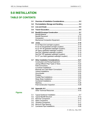
CAMBRIDGE CALL CENTER1144 Industrial RoadCambridge, Ontario, N3H4W4Tel: (519) 650-1550Toll Free: (888) 893-7827Fax: (519) 650-1553Call ntNewHampshireOregonIdahoConnecticutRhode aMassachusettsNew YorkNorthDakotaWisconsinNew MissouriMarylandVirginiaKentuckyNew MexicoOklahomaNorth labamaGeorgiaAlaskaTexasLouisianaFloridaPuerto RicoHawaiiCORONA CALL CENTERHOUSTON CALL CENTER1223 Sherborn Street, Ste 102Corona, CA 92879Tel: (951) 898-0770Toll Free: (877) 701-7827Fax: (951) 898-9561Corporate Headquarters4018 Westhollow Pkwy.Houston, TX 77082Tel: (281) 558-3000Toll Free: (800) 999-3009Fax: (281) 558-9000Distribution CentersSacramento, CAPhoenix, AZMontreal, CANKansas City, MO830 W. National Drive, Ste 150Sacramento, CA 958341250 East Hadley Street, Ste 2Phoenix, AZ 850343067 Rue Joseph A. BombardierLaval, QC H7P 6C51836 Levee RoadNorth Kansas City, MO 64116Orlando, FLSalt Lake City, UTAtlanta, GAIndianapolis, IN601 Gills Drive, Ste 100Orlando, FL 328242801 West Parkway Blvd.Salt Lake City, UT 841195307 Peachtree Industrial Blvd.Chamblee, GA 303416119 Guion RoadIndianapolis, IN 46254Richmond, VASeattle, WA2913 Transport Street, Ste 101Richmond, VA 2323413605 52nd Street EastSumner, WA 98390
Table of ContentsE - SECTIONPRODUCTSGENERAL TERMS & CONDITIONS STARGRIPSeries 3000, 3000OS, 3000S, 3000T, 3100P, 3100SMechanical Joint Wedge Action Restraints for Ductile Iron pipe.PVC STARGRIP Mechanical Joint Wedge Action Restraint for C900/C905 and IPSPVC pipe.Nom. pipe size: 3"-36"pg. 33 - 36Mechanical Joint 360 ring type restraint system designed forC900/C905 and IPS PVC pipe.F - SECTIONNom. pipe size: 3"-48"pg. 19 - 32Series 3500G - SECTIONpg. 3 - 18Series 4000, 4000G2, 4100P, 4400PVC RING LOCK (PVCGRIP )PVC PIPE RESTRAINERSSeries 1000, 1100, 1200, 1200R, 1000G2, 1100G2, 1200G2Joint Restraint for MJ and Push On fittings for C900/C905 and IPSPVC pipe to pipe conections and PVC pressure fittings.STARFLEX Nom. pipe size: 4"-16"pg. 37 - 66Nom. pipe size: 4"-48"pg. 67 - 82Series 5000, 5100, 5200, 5300Flexible expansion joint for the protection of water, wastewaterand industrial pipelines.STARFLANGE Nom. pipe size: 3"-48"pg. 83 - 86Series 3200Restraint flange adapter coupling for Ductile Iron pipe.PVC STARFLANGE Nom. pipe size: 3"-36"pg. 87 - 90Series 4200Restraint flange adapter coupling for PVC pipe.SUPER FLANGE Nom. pipe size: 3"-36"pg. 91 - 96Series 7200H - SECTIONpg. 2Restrains and adapts plain end pipe to flanged componentsMJ x MJ ADAPTERNom. pipe size: 3"-36"pg. 97 - 100Series 100Nom. pipe size: 3"-36"Adapter for MJ Bell ConnectionsADAPTER FLANGEpg. 101 - 104Series 200, 400Flange adapters for Ductile Iron and Steel pipe. Standard andheavy duty.HEAVY DUTY RETAINER GLANDNom. pipe size: 3"-36"pg. 105 - 108Series 600Mechanical joint retainer glands for ductile iron pipe.HARDWAREMEMBERNom. pipe size: 3"-36"pg. 109 - 112Starlug, Eye Bolts, Zinc Caps Please refer to Star Pipe Products’ web site (www.starpipeproducts.com) for updated information.JRCAT17.01 REGISTERED TRADEMARK OF STAR PIPE PRODUCTSSTAR PIPE PRODUCTSHOUSTON CORPORATE TOLL FREE 1-800-999-3009 FAX 281-558-9000www.starpipeproducts.comPage 1
General Terms and ConditionsGENERALThese terms and conditions shall control with respect to any purchase order or sale of Seller’s products. No waiver,alteration or modification of these terms and conditions whether on Buyer’s purchase order or otherwise shall bevalid unless the waiver, alteration or modification is specifically accepted in writing and signed by an authorizedrepresentative of Seller.DELIVERYSeller will make every effort to complete delivery of products as indicated on Seller’s acceptance of an order,but Seller assumes no responsibility or liability, and will accept no backcharge, for loss or damage due to delayor inability to deliver caused by acts of God, war, labor difficulties, accident, delays of carriers, by contractors orsuppliers, inability to obtain materials, shortages of fuel and energy, or any other causes of any kind whatsoeverbeyond the control of Seller. Seller may terminate any contract of sale of its products without liability of any nature,by written notice to Buyer, in the event that the delay in delivery or performance resulting from any of the aforesaidcauses shall continue for a period of sixty (60) days. Under no circumstances shall Seller be liable for any special orconsequential damages or for loss, damage, or expense (whether or not based on negligence) directly or indirectlyarising from delays or failure to give notice of delay.WARRANTYSeller warrants for one year from the date of shipment Seller’s manufactured products to the extent that Seller willreplace those having defects in material or workmanship when used for the purpose and in the manner which Sellerrecommends. If Seller’s examination shall disclose to its satisfaction that the product is defective, and an adjustmentis required, the amount of such adjustment shall not exceed the net sales price of the defective products onlyand no allowance will be made for labor or expense of repairing or replacing defective product or workmanshipor damage resulting from the same. No adjustment shall be implemented unless product in question is returnedto seller in its originally installed condition, still connected to other components of the joint. Buyer must contactSeller as quickly as possible so Seller can assess product in its installed condition. No claims will be honored unlessclaim is made within forty five (45) days of the defect being found. Where engineering design or fabrication workis supplied, Buyer’s acceptance of Seller’s design or of delivery of work shall relieve Seller of all further obligation,other than expressed in Seller’s product warranty. THIS IS SELLER’S SOLE WARRANTY. SELLER MAKES NO OTHERWARRANTY OF ANY KIND, EXPRESSED OR IMPLIED AND ALL IMPLIED WARRANTIES OF MERCHANTABILITY AND FITNESSFOR A PARTICULAR PURPOSE WHICH EXCEED SELLER’S AFORESTATED OBLIGATION ARE HEREBY DISCLAIMED BY SELLERAND EXCLUDED FROM THIS WARRANTY. Seller neither assumes, nor authorizes any person to assume for it, any otherobligation in connection with the sale of its engineering designs or product. This warranty shall not apply to anyproducts or parts of products which (a) have been repaired or altered outside of Seller’s factory, in any manner;(b) have been subjected to misuse, negligence or accidents; (c) have been used in a manner contrary to Seller’sinstructions or recommendations. Seller shall not be responsible for design errors due to inaccurate or incompleteinformation supplied by Buyer or its representatives. This warranty is non-transferable.LIABILITYSeller will not be liable for any loss, damage, cost of repairs, incidental or consequential damages of any kind,whether based upon warranty (except for the obligation accepted by Seller under "Warranty" above), contractor negligence, arising in connection with the design, manufacture, sale, use or repair of the products or of theengineering designs supplied to Buyer.DISCLAIMERPer AWWA/ANSI C110 A21.10, the flanged joint is generally specified for above ground service. Underground use ofthe flanged joint is generally not desirable due to the rigidity of the joint.RETURNSSeller cannot accept return of any products unless its written permission has been first obtained, in which case samewill be credited subject to the following: (a) All material returned must, on its arrival at Seller’s plant, be found tobe in first-class condition; if not, cost of putting in saleable condition will be deducted from credit memoranda;(b) A handling charge deduction of twenty-five percent (25%) will be made from all credit memoranda issued formaterial returned; (c) Transportation charges, if not prepaid will be deducted from credit memoranda.SHIPMENTSAll products sent out will be carefully examined, counted and packed. The cost of any special packing or specialhandling caused by Buyer’s requirements or requests shall be added to the amount of the order.No claim for shortages will be allowed unless made in writing within ten (10) days of receipt of a shipment.Claims for products damaged or lost in transit should be made on the carrier, as Seller’s responsibility ceases, andtitle passes, on delivery to the carrier.PRODUCTSOrders covering special or non-standard products are not subject to cancellation except on such terms as Sellermay specify on application.PRICESPrices and designs are subject to change without notice. All prices are F.O.B. Point of Shipment, unless otherwisestated.TAXESThe amount of any sales, excise or other taxes, if any, applicable to the products covered by this order, shall beadded to the purchase price and shall be paid by Buyer unless Buyer provides Seller with an exemption certificateacceptable to the taxing authorities. REGISTERED TRADEMARK OF STAR PIPE PRODUCTSSTAR PIPE PRODUCTSHOUSTON CORPORATE TOLL FREE 1-800-999-3009 FAX 281-558-9000www.starpipeproducts.comPage 2
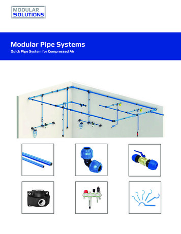
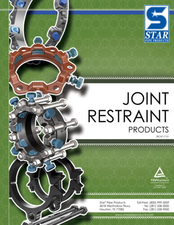
Joint Restraint ProductsStargrip series 3000 Mechanical Joint Wedge Action Restraintfor Ductile Iron PipeINFORMATIONThe Stargrip Mechanical Joint Restraint System is a uniqueproduct with a proven design that provides an exceptionalrestraining system for mechanical joint fittings (AWWA C153 orC110), valves, fire hydrants and all classes of ductile iron pipe.More Adaptable for Field UseStargrip series 3000 for Ductile Iron PipeFEATURES & ADVANTAGES Gland is made from high strength Ductile Iron per ASTM A536, Grade 65-45-12 and is compatible with all Mechanical Jointsconforming to ANSI/AWWA C111/A21.11. The Wedge Assembly is designed with a Break-Off Torque Control Nut that will only break off in one direction, ensuring properinstallation. The Stargrip offers a full 5 deflection through 12" size, 3 on 14"-24", 2 on 30"-36" and 1 on 42"-48". Minimum safety factor of 2:1 Stargrip sizes 3"-36" are listed with Underwriters Laboratories Inc. and sizes 3"-12" are approved by Factory Mutual Research. The Wedges are heat treated to a minimum of 370 BHN. The Wedge Assembly is designed to fit specific pipe sizes and is field repairable. No special tools are required for installation of the Stargrip . Stargrip eliminates tie rods and thrust blocks. Standard gland color is Graphite Black (RAL 9011). Stargrip may also be used on steel pipe* up to 12" (*transition gasket required on 12" and under). For 14" and larger steelapplications, contact Star Pipe.SAMPLE SPECIFICATIONSRestrainer mechanism shall be integrated into the design of the follower gland. As the mechanism is activated, multiple wedging action shall be impartedagainst the pipe increasing its resistance as internal pressure increases. After burial of the restraining mechanism, joint flexibility shall be maintained.The actuating bolt shall be threaded into the restraining wedge and have a 1-1/4" hex operating nut. The operating nut shall be threaded onto theactuating bolt, not swaged or riveted. The restraining twist off nut bolt system shall have a torque-limiting feature designed to break off at preset torquelevels, thus insuring proper action of restraining device. Glands shall be manufactured of high strength ductile iron in accordance with ASTM A536Grade 65-45-12 requirements. The wedge shall be manufactured of high strength ductile iron and be heat treated to a minimum hardness of 370 BHN.Applicable dimensions shall conform to ANSI/AWWA C111/A21.11 and shall be incorporated into the mechanical joint restraint so that the devicefacilitates use with standard mechanical joint bells.The mechanical joint restraint mechanism shall have a maximum water working pressure of 350 PSI for sizes 3"-16" and 250 PSI for sizes 18" andabove. All sizes shall have a minimum safety factor of 2:1 (i.e. twice the maximum pressure rating of the restraint). The mechanical joint restraintmechanism shall be Underwriters Laboratories listed on size 3" through 36" and Factory Mutual Research Approved on size 3"-12". The restraintmechanism shall be Star Pipe Products Stargrip series 3000 or an approved equal.JRCAT17.02 REGISTERED TRADEMARK OF STAR PIPE PRODUCTSSTAR PIPE PRODUCTSHOUSTON CORPORATE TOLL FREE 1-800-999-3009 FAX 281-558-9000www.starpipeproducts.comPage 3
Joint Restraint ProductsStargrip series 3000 Mechanical Joint Wedge Action Restraintfor Ductile Iron PipeTECHNICAL INFORMATION0.750.12STARGRIP 3000 SPECIFICATIONS*NOM.SIZEMAX PRESSURERATING(PSI)ABCDEFF W/NUTSTWISTED .5439.1246.0053.1260.00NO. OF NO. OF APPROX WT.WEDGES 1620242832791317233154606972170197242425500*All dimensions in inches except where indicated.Notes: Stargrips must be adequately wrapped or protected if they are covered by concrete to ensure that concrete does not enter the wedge pocket. For applications exceeding the maximum pressure ratings listed, please contact Star Pipe Products for recommendations (see Tandem Stargrip onpage 10). For applications with vertical offsets, please contact Star Pipe Products for technical assistance. For applications on existing pipe, the pipe needs to be structurally sound and the surface needs to be relatively free of any corrosive by-products inorder for the wedges to function properly. Please contact Star Pipe Products for technical assistance. Sizes 42" & 48" require extra long 1 ¼" x 8 ½" T-bolts.JRCAT17.02 REGISTERED TRADEMARK OF STAR PIPE PRODUCTSSTAR PIPE PRODUCTSHOUSTON CORPORATE TOLL FREE 1-800-999-3009 FAX 281-558-9000www.starpipeproducts.comPage 4
Joint Restraint ProductsOversized Stargrip series 3000OS Mechanical Joint Wedge Action Restraintfor A, B, C & D Pit Cast PipeINFORMATIONThe oversized Stargrip series 3000OS has the same featuresas the series 3000 except the bore (ID) has been increased toaccomodate Class A, B, C, & D pit cast pipe.Oversized Accomodates ClassA,B,C & D Pit Cast PipeStargrip series 3000OSTECHNICAL INFORMATIONSTARGRIP 3000OS SPECIFICATIONS*NOM.SIZEMAX PRESSURERATING(PSI)B.C.DIAMETERBOLT HOLESNOMINAL GLANDI.D.LIP THICKNESSAPPROX .7514.0016.2518.7521.004 x 7/86 x 7/86 x 7/88 x 7/88 x 7/810 x 7/812 x 70.270.230.219131823315460*All dimensions in inches except where indicated.JRCAT17.02 REGISTERED TRADEMARK OF STAR PIPE PRODUCTSSTAR PIPE PRODUCTSHOUSTON CORPORATE TOLL FREE 1-800-999-3009 FAX 281-558-9000www.starpipeproducts.comPage 5
Joint Restraint ProductsStargrip series 3000 & 3000OS Mechanical Joint Wedge Action Restraintfor Ductile Iron PipeINSTALLATION INSTRUCTIONS - SIZES 3"- 48"STEP 1To ensure the rubber gasket will seal moreeffectively, clean and remove all loose materialsand rust from the mating surfaces. Lubricate thegasket and plain end by brushing either soapywater or pipe lubricant. Slide the Stargrip onthe plain end with lip extension towards theplain end, followed by the MJ gasket. Do notremove rubber washers prior to installation.Washers have been provided for proper wedgeplacement during shipment and installation.STEP 2After insertion of the pipe into the bell of thefitting, firmly press the gasket into the gasketrecess. During this process the joint should bekept straight.STEP 4When tightening bolts, it is essential that thegland be brought up toward the bell flangeevenly, maintaining approximately the samedistance between the gland and the face of theflange at all points around the socket. All T-boltsshould be tightened until they are in within thetorque range per ANSI/AWWA C600 (See TableA). T-Bolts should be tightened alternately onthe opposite sides (Star Pattern).STEP 3Slide the Stargrip toward the MJ bell with thegland lip against the gasket. Insert T-bolts andhand tighten nuts.IMPORTANT: Make deflection after joint isassembled but before tightening T-bolts.STEP 5Tighten the torque limiting twist off nuts in aclockwise direction until all wedges are in firmcontact with the pipe surface.Continue tightening in an alternative mannergoing on the opposite sides [Star Pattern], untilall of nuts have been twisted off. Never turn asingle nut over 180 degrees without alternatingto another nut.STEP 6If removal is necessary, utilize the 5/8″ hex headprovided. [If reassembly is required, assemble thejoint in the same manner as above and tighten thewedge bolt to 90 ft-lbs on sizes 3"-20", 120 ft-lbson sizes 24"-36" & 130 ft-lbs on sizes 42"-48"].(TABLE A) T-HEAD BOLT & NUT DETAILSPIPE SIZE(IN)34-2430-3642-48BOLT SIZE(IN)5/83/411 1/4RANGE1 OFTORQUE (FT-LBS)45-6075-90100-120120-150These torque ranges are requirements of AWWA C6001Notes: If effective sealing is not attained at the maximum torque indicated, then the joint should be disassembled, thoroughly cleaned, and reassembled.Overstressing the bolts to compensate for poor installation practice is not acceptable. Not to be used on plain end fittings or PVC or HDPE pipe. Stargrip may also be used on steel pipe* up to 12" (*transition gasket required on 12" and under). For 14" and larger steel applications, contact StarPipe. Stargrips must be adequately wrapped or protected if they are covered by concrete to ensure that concrete does not enter the wedge pocket. For applications exceeding the maximum pressure ratings listed, please contact Star Pipe Products for recommendations (see Tandem Stargrip on page 10). For applications with vertical offsets, please contact Star Pipe Products for technical assistance. For applications on existing pipe, the pipe needs to be structurally sound and the surface needs to be relatively free of any corrosive by-products in orderfor the wedges to function properly. Please contact Star Pipe Products for technical assistance. Pressure ratings shall not exceed the maximum pressure rating of the ductile iron pipe it is installed on.JRCAT17.02 REGISTERED TRADEMARK OF STAR PIPE PRODUCTSSTAR PIPE PRODUCTSHOUSTON CORPORATE TOLL FREE 1-800-999-3009 FAX 281-558-9000www.starpipeproducts.comPage 6
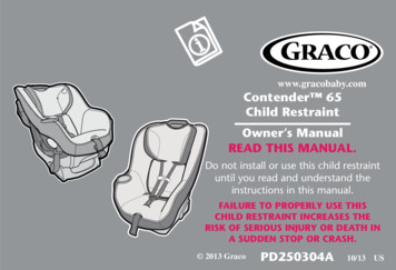
Joint Restraint ProductsSplit Stargrip series 3000S Split Mechanical Joint Wedge Action Restraintfor New or Existing Ductile Iron PipeINFORMATIONThe Split Stargrip is used for restraining new or existing ductileiron mechanical joint fittings, valves, fire hydrants and allclasses of ductile iron pipe. Split Stargrip pressure rating pertable on next page.The unique split design makes installation fast and simple.Easy InstallationStargrip series 3000S for Ductile Iron Pipe.FEATURES & ADVANTAGES Split design Stargrip Series 3000S for easy installation on new or existing Ductile Iron Mechanical Joint systems. Gland is made from high strength Ductile Iron per ASTM A536, Grade 65-45-12 and is compatible with allMechanical Joints conforming to ANSI/AWWA C111/A21.11. The Wedge Assembly is designed with a Break-Off Torque Control Nut that will only break off in one direction,ensuring proper installation. Offers a full 5 deflection through 12 size, 3º on 14 -24 , 2º on 30 -36 and 1º on 42 -48 . Minimum safety factor of 2:1 The Wedges are heat treated to a minimum of 370 BHN. The Wedge Assembly is designed to fit specific pipe sizes and is field repairable. Clamping bolts per SAE J429 Grade 5 steel Eliminates tie rods and thrust blocks Standard gland color is Graphite Black (RAL 9011). Split Stargrip may also be used on steel pipe* up to 12" (*transition gasket required on 12" and under). For 14"and larger steel applications, contact Star Pipe.SAMPLE SPECIFICATIONSRestraint mechanism shall be of split design for use on new or existing mechanical joints. As the mechanism is activated, multiple wedging action shallbe imparted against the pipe increasing its resistance as internal pressure increases. After burial of the restraining mechanism, joint flexibility shall bemaintained.The actuating bolt shall be threaded into the restraining wedge and have a 1-1/4" hex operating nut. The operating nut shall be threaded onto theactuating bolt, not swaged or riveted. The restraining twist off nut bolt system shall have a torque-limiting feature designed to break off at preset torquelevels, thus insuring proper action of restraining device. Glands shall be manufactured of high strength ductile iron in accordance with ASTM A536Grade 65-45-12 requirements. The wedge shall be manufactured of high strength ductile iron and be heat treated to a minimum hardness of 370 BHN.Applicable dimensions shall conform to ANSI/AWWA C111/A21.11 and shall be incorporated into the mechanical joint restraint so that the devicefacilitates use with standard mechanical joint bells.The mechanical joint restraint mechanism shall have a maximum water working pressure of 350 PSI for sizes 3"-8", 300 PSI for sizes 10"-16", 200PSI for sizes 18"-36" and 175 PSI for sizes 42"-48". All sizes shall have a minimum safety factor of 2:1 (i.e. twice the maximum pressure rating of therestraint). The restraint mechanism shall be Star Pipe Products Split Stargrip series 3000S or an approved equal.JRCAT17.02 REGISTERED TRADEMARK OF STAR PIPE PRODUCTSSTAR PIPE PRODUCTSHOUSTON CORPORATE TOLL FREE 1-800-999-3009 FAX 281-558-9000www.starpipeproducts.comPage 7
Joint Restraint ProductsSplit Stargrip series 3000S Split Mechanical Joint Wedge Action Restraintfor New or Existing Ductile Iron PipeTECHNICAL INFORMATION0.750.12CLAMPING BOLT SIZESERIES 3000S(IN)BOLT SIZE(IN)QTY3-68-101214-24303642-485/8 x 3 1/23/4 x 3 1/23/4 x 47/8 x 3 3/41 x 3 3/47/8 x 3 3/41 1/8 x 4 1/22222244SPLIT STARGRIP 3000S SPECIFICATIONS*NOM.SIZEMAX PRESSURERATING(PSI)ABCDEFF W/NUTSTWISTED 7550.6257.503/47/87/87/87/87/87/87/87/87/87/81 1/81 1/81 3/81 68101212141620242832T-BOLTS APPROX 607677131201240581664*All dimensions in inches except where indicated.Notes: Sizes 42" & 48" require extra long 1 ¼" x 8 ½" T-bolts. For applications with vertical offsets, please contact Star Pipe Products for technical assistance. Pressure ratings shall not exceed the maximum pressure rating of the ductile iron pipe it is installed on.JRCAT17.02 REGISTERED TRADEMARK OF STAR PIPE PRODUCTSSTAR PIPE PRODUCTSHOUSTON CORPORATE TOLL FREE 1-800-999-3009 FAX 281-558-9000www.starpipeproducts.comPage 8
Joint Restraint ProductsSplit Stargrip series 3000S Split Mechanical Joint Wedge Action Restraintfor New or Existing Ductile Iron PipeINSTALLATION INSTRUCTIONS - SIZES 3"- 48"STEP 1Existing joint must be disassembled andthoroughly cleaned. If necessary, replace theexisting gasket with a field cut gasket. Brushboth the gasket and the plain end with soapywater or approved pipe lubricant, which meetsANSI/AWWA C111/A21.11. Firmly insert thesplit gasket into the bell cavity.STEP 2Remove the clamping bolts from the splitStargrip . Loosely assemble the halves onthe pipe, making sure that the lip extension istowards the mechanical joint bell. Then reinstallthe clamping bolts. Do not remove rubberwashers prior to installation. Washers have beenprovided for proper wedge placement duringshipment and installation.STEP 4Tighten Clamping bolts on the Split Stargrip to the following:3" - 12": 100-125 FT-LBS.14" - 36": 250-275 FT-LBS.42" - 48": 300-325 FT-LBS.STEP 5Tighten the T-bolts to normal range of bolttorque. It is necessary that the gland be broughtup toward the bell flange evenly, maintainingapproximately the same distance between thegland and the face of the flange at all pointsaround the socket. T-Bolts should be tightenedalternately on the opposite sides (Star Pattern)(see table A).BOLT SIZE(IN)5/83/411 1/4Slide the loosely assembled Stargrip towardsthe MJ bell and insert T-Bolts and hand-tightenthe nuts.STEP 6Hand tighten the torque limiting twist off nuts ina clockwise direction until all wedges are in firmcontact with the pipe surface.Continue tightening in an alternative mannergoing on opposite sides [Star Pattern], until allof the nuts have been twisted off. Never turn asingle nut over 180 degrees without alternatingto another nut.If removal is necessary, utilize the 5/8" hex headprovided. [If reassembly is required, assemble thejoint in the same manner as above and tighten thewedge bolts to 90 ft-lbs on sizes 3"-20", 120 ft-lbson sizes 24"-36" & 130 ft-lbs on sizes 42"-48"].(TABLE A) T-HEAD BOLT & NUT DETAILSPIPE SIZE(IN)34-2430-3642-48STEP 3RANGE1 OFTORQUE (FT-LBS)45-6075-90100-120120-150These torque ranges are requirements of AWWA C6001Notes: Not to be used on plain end fittings or PVC or HDPE pipe. May also be used on steel pipe* up to 12" (*transition gasket required on 12" and under). For 14" and larger steel applications, contact Star Pipe. Stargrips must be adequately wrapped or protected if they are covered by concrete to ensure that concrete does not enter the wedge pocket. For applications exceeding the maximum pressure ratings listed, please contact Star Pipe Products for recommendations (see Tandem Stargrip onpage 10). For applications with vertical offsets, please contact Star Pipe Products for technical assistance. For applications on existing pipe, the pipe needs to be structurally sound and the surface needs to be relatively free of any corrosive by-products inorder for the wedges to function properly. Please contact Star Pipe Products for technical assistance.JRCAT17.02 REGISTERED TRADEMARK OF STAR PIPE PRODUCTSSTAR PIPE PRODUCTSHOUSTON CORPORATE TOLL FREE 1-800-999-3009 FAX 281-558-9000www.starpipeproducts.comPage 9
NOTES:JRCAT17.02 REGISTERED TRADEMARK OF STAR PIPE PRODUCTSSTAR PIPE PRODUCTSHOUSTON CORPORATE TOLL FREE 1-800-999-3009 FAX 281-558-9000www.starpipeproducts.comPage 10
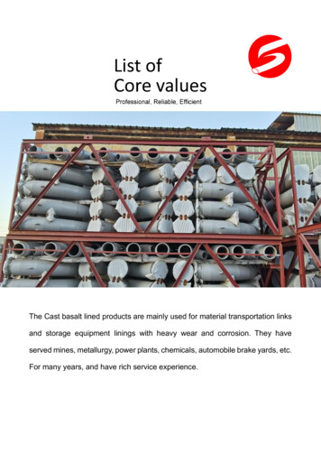
Joint Restraint ProductsTandem Stargrip series 3000TFor High Pressure DI Pipe to MJ Fitting ApplicationsINFORMATIONThe Tandem Stargrip Mechanical Joint Restraint System was designedfor high pressure Ductile Iron Pipe to MJ Fitting applications (AWWA C153or C110). Tandem Stargrip pressure rating per table below is based onuse with PC350 or TC50 (or above) ductile iron pipe.For High PressureDuctile Iron Pipe to MJFitting ApplicationsStargrip series 3000T for Ductile Iron Pipe.TECHNICAL INFORMATIONDATA FOR HIGH PRESSURE STARGRIP ASSEMBLYNOM.SIZEDI PIPEODPRESSURERATING (PSI)BOLT ROD SIZET-BOLT SIZET-BOLT TORQUE(FT-LBS)COUPLING NUTGRADE 5 STEELWT33.967005/8 x 65/8 x 445-605/8 x 2 1/81844.807003/4 x 123/4 x 4 1/275-903/4 x 2 1/42866.907003/4 x 123/4 x 4 1/275-903/4 x 2 1/44189.057003/4 x 123/4 x 4 1/275-903/4 x 2 1/4491011.106003/4 x 123/4 x 4 1/275-903/4 x 2 1/4691213.206003/4 x 123/4 x 575-903/4 x 2 1/4881415.305003/4 x 123/4 x 590-1103/4 x 2 1/41411617.405003/4 x 123/4 x 590-1103/4 x 2 1/41591819.503503/4 x 123/4 x 5120-1403/4 x 2 1/41772021.603503/4 x 123/4 x 5 1/2120-1403/4 x 2 1/41912425.803503/4 x 123/4 x 5 1/2120-1403/4 x 2 1/42943032.003001 x 121 x 6 1/2120-1401 x 2 3/45203638.303001 x 121 x 7 1/2120-1401 x 2 3/46164244.503001 1/4 x 121 1/4 x 8 1/2120-1501 1/4 x 311184850.803001 1/4 x 121 1/4 x 8 1/2120-1501 1/4 x 31357*All dimensions in inches except where indicated.Notes: For applications with vertical offsets, please contact Star Pipe Products for technical assistance.JRCAT17.02 REGISTERED TRADEMARK OF STAR PIPE PRODUCTSSTAR PIPE PRODUCTSHOUSTON CORPORATE TOLL FREE 1-800-999-3009 FAX 281-558-9000www.starpipeproducts.comPage 11
Joint Restraint ProductsTandem Stargrip series 3000TFor High Pressure DI Pipe to MJ Fitting ApplicationsINSTALLATION INSTRUCTIONSTandem Stargrip Installation Instructions1. To ensure the rubber gasket will seal more effectively, clean and remove all loose materials and rust from the mating surfaces.Lubricate the gasket and plain end by brushing either soapy water or pipe lubricant. Slide both Stargrip Glands on the plainend, followed by the MJ gasket. Ensure that the lip of Stargrip Glands are facing towards the MJ Gasket & MJ bell. Do notremove rubber washers prior to installation. Washers have been provided for proper wedge placement during shipment andinstallation.2. After insertion of the pipe into the bell of the fitting, firmly press the gasket into the gasket recess. During this process the jointshould be kept straight.3. Slide the first Stargrip toward the MJ bell with the gland lip against the gasket. Insert T-bolts and hand tig
Star Pipe Products 4018 Westhollow Pkwy. Houston, TX 77082 Toll-Free: (800) 999-3009 Tel: (281) 558-3000 Fax: (281) 558-9000 www.starpipeproducts.com . manufacture, sale, use or repair of the products or of the engineering designs supplied to Buyer. DISCLAIMER Per AWWA/ANSI C110 A21.10, the flanged joint is generally specified for above .