Transcription
.3651 N. Hwy. 89 Chino Valley, AZ 86323(928) 636-7080 www.p-a-g.netWARNINGFORD F150BODY LIFT KITINSTALLATION INSTRUCTIONS20032” KIT# 700423” KIT# 70043This kit should only be installed on a vehicle that is ingood working condition. Before you install the kit, thoroughly inspect the vehicle for corrosion or deformationof the sheet metal around the factory body mounts. Ifthe vehicle is suspected to have been in a collision ormisused, do not install this kit. Off-road use of yourvehicle with this kit installed may increase the stressapplied to the factory body mounts. We do not recommend that any vehicle with a body lift kit installed beinvolved in any extreme off-road maneuvers such asjumping. Failure to observe this warning may result inserious personal injury and/or severe damage to yourvehicle.WARNINGMany states and municipalities have laws restrictingbumper heights and vehicle lifts. Consult state andlocal laws to determine if the changes you intend tomake to the vehicle comply with the law.WARNINGInstallation of a Performance Automotive Group bodylift kit will change the vehicle’s center of gravity andhandling characteristics both on- and off-road. Youmust drive the vehicle safely! Extreme care must betaken to prevent vehicle rollover or loss of control,which could result in serious injury or death. Avoid sudden sharp turns or abrupt maneuvers and always makesure all vehicle occupants have their seat belts fastened.WARNINGThe installation of larger tires may reduce the effectiveness of the braking system.WARNINGAlways wear eye protection when operating powertools.WARNINGBefore you install this kit, read and understand allinstructions, warnings, cautions, and notes in thisinstruction sheet and in the vehicle owner’s manual.WARNINGBefore you install this kit, block the vehicle tires to prevent the vehicle from rolling.CAUTIONWARNINGProper installation of this kit requires knowledge of thefactory recommended procedures for removal andinstallation of original equipment components. We recommend that the factory shop manual and any specialtools needed to service your vehicle be on hand duringthe installation. Installation of this kit without properknowledge of the factory recommended proceduresmay affect the performance of these components andthe safety of the vehicle. We strongly recommend thata certified mechanic familiar with the installation of similar components install this kit.Accidental deployment of the air bag can result in serious personal injury or death. To avoid accidentaldeployment during installation of the kit, the Supplemental Restraint System (SRS, or airbag) must remaindeactivated. Do not allow anyone near the airbag during installation. Refer to the factory service manual orowner's manual for the recommended procedure todisable the SRS. After you install the kit, reactivate theSRS before driving the vehicle.NOTEWARNINGPerformance Automotive Group recommends usingthe Loctite supplied in the kit on the threads of all kitnuts and bolts unless specified otherwise in theseinstructions.DO NOT combine suspension, body, or other liftdevices. Use of vehicle with combined lifts may resultin unsafe and/or unexpected handling characteristics.12003 F150 - Kit 70043
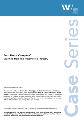
A. Before you start.NOTEAs you read through this procedure, note that eachpart referenced has the same callout numberthroughout. Also, the part number in the text matchesthe corresponding part number in the art. Kit partsare prefaced by the word kit in italics.NOTEYou will find it easier to keep track of hardware ifimmediately after removal you put the fasteners foreach subassembly in a paper lunch bag and write onthe bag where they go.1. Read all warnings and instructions completely andcarefully before you begin.2. Check to make sure the kit is complete (refer to theParts List, section E).3. Only install this kit on the vehicle for which it isintended. If anytime during the installation youencounter something different from what is outlinedin the instructions, call technical support at (928)636-0979.4. Park the vehicle on a clean, dry, flat, level surfaceand block the tires so the vehicle cannot roll in eitherdirection.5. Disconnect both battery cables.a. Disconnect the negative cable (1) first, then thepositive cable (2) from the battery (3).6. Remove two covers (4 and 5) and the airbag fuse (6)from the fuse panel (7).22003 F150 - Kit 70043
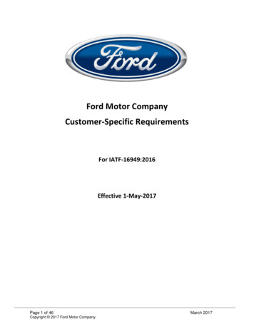
B. Get ready to install the kit.1. Remove the front bumper.a. Measure distance between the front bumper (8)and front fenders (9). Record measurement.b. If so equipped, remove four bolts (10) and twotow hooks (11) from frame (12) ends.c. If so equipped, remove two connectors (13) fromfog lamps (14).d. Remove eight panel clips (15) and air flap (16)from front bumper (8) and core support (17).e. Remove four nuts (18) and front bumper (8) fromframe (12).32003 F150 - Kit 70043
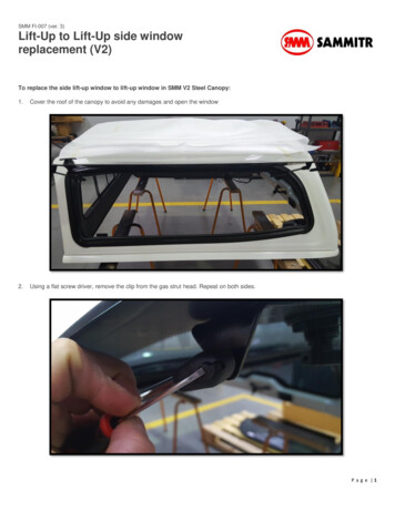
2. Remove the rear bumper.a. Disconnect two license plate lights (19) from therear bumper (20).b. Remove four nuts (21) and rear bumper (20)from frame (12).3. Under the hood.a. Remove three screws with captive washers (22)and fuel injection cover (23) from the throttlebody (24).b. Remove clamp (25) from air duct (26) and throttle body (24).c. Remove two hoses (27) from air duct (26) andthrottle body (24).d. Loosen clamp (28) and remove air duct (26) fromair filter housing (29). Move move air duct out ofway.e. Remove air filter (30) from air filter housing (29)and set aside.42003 F150 - Kit 70043
f.Remove spare tire crank (31) from clips (32).g. Remove seven screws (33) from radiator shroud(34) and core support (17).h. Remove two screws (33) and radiator shroud(34) from fan shroud (35).i.Remove two screws (36) from fan shroud (35)and radiator (37).j.Pull radiator shroud (34) up and back from fanshroud (35), off of two top click-in mounting tabs(38). Rest fan shroud on fan.52003 F150 - Kit 70043
WARNINGEnsure radiator has cooled completely before removing radiator cap. Radiator coolant is HOT and UNDERPRESSURE. Serious personal injury may result if capis removed before radiator has cooled.k. Remove radiator cap (39) from overflow bottle(40).l.Drain radiator (37) into a clean container.m. Squeeze clamp (41) and remove hose (42) fromradiator (37).n. If equipped with automatic transmission, removetwo snap off line covers (43) (if so equipped / notshown) and remove transmission cooling lines(44 and 45).o. Squeeze two clamps (46 and 47) and removeupper radiator hose (48) and lower radiator hose(49) from radiator (37).62003 F150 - Kit 70043
p. Remove two bolts with captive washers (50), fourbrackets (51 and 52), and radiator (37) from coresupport (17). Set radiator aside.q. Remove fan shroud (35) from vehicle and setaside.r.Remove clip (53) from lines (54 and 55). Clip willnot be reused.s. Loosen nut (56) from stud (57) so bracket (58)moves freely.t.Remove line (59) from clip (60) on frame (12)driver side.u. Remove three screws (61) and transmissioncooler (62) from the core support (17).v.Remove two screws (63) and power steeringcooler (64) from the core support (17).w. Remove clip (65) from lines (59 and 66). Clip willnot be reused.x. Remove bolt (67) from the core support (17).72003 F150 - Kit 70043
4. Along the frame rails.NOTEStep 4.a. is only for vehicles with the brake modulemounted on the frame. Other models skip this step.You may find it easier to remove the brake module ifyou first remove the driver side inner fender, but this isnot strictly necessary.a. Remove three bolts (68) and brake module (69)from bracket (70).b. Remove line (59) from clip (71) on frame (12)driver side.c. Remove clip (72) and line (59) from frame (12)driver side.d. Remove two clips (73) and harness (74) fromframe (12) driver side.e. Remove bolt (75) and safety cable (76) fromframe (12) driver side.82003 F150 - Kit 70043
NOTEFor some vehicles, the chassis ground is on theframe in front of the wheel. For other models, theground is behind the wheel.f.If so equipped, remove bolt (77) and bracket (78)from frame (12) passenger side.g. Remove bolt (79) and ground strap (80) fromframe (12) passenger side.h. Remove bolt (75) and safety cable (76) fromframe (12) passenger side.NOTEStep 5 is only for vehicles with the automatic transmission shown. Other models skip this step.5. Under the cab.a. Remove two bolts (81) and shift cable bracket(82) from transmission (83).92003 F150 - Kit 70043
6. Inside the cab.NOTEEnsure steering shaft does not turn independently ofthe steering gearbox. This could cause the air bag system to malfunction, resulting in serous personal injuryor damage to the equipment.a. Straighten steering wheel and strap the wheel soit will not turn.b. Loosen bolt (84) from the steering u-joint (85)under the dash, slide u-joint down to removefrom steering wheel shaft (86).NOTEStep 6.c. and 6.d. are for regular, extended, and crewcab models.c. Remove two scuff plates (87) and two kick panels (88) from front of cab floor (89).d. Pull carpet (90) away and remove two rubbercaps (91) from front of cab floor (89).102003 F150 - Kit 70043
NOTEStep 6.e. and 6.f. are for regular cab models only.Other models skip these steps.e. Remove three nuts (92) from studs (93) and tray(94) from rear of cab floor (89).f.Fold carpet (90) forward and remove two rubbercaps (91) from cab floor (89).NOTESteps 6.g. through 6.k. are for extended cab modelsonly. Other models skip these steps.g. Remove two scuff plates (95) from rear of cabfloor (89).h. Fold rear seat bottom (96) forward and removetwo bolts (97) from rear seat and cab floor (89).i.Remove three bolts (97), three nuts (98), andrear seat bottom (96) from studs (99) and cabfloor (89).j.Fold carpet (90) forward and remove two rubbercaps (91) from cab floor (89).k. Reach under carpet (90) and remove two rubbercaps (91) from cab floor (89) just behind frontseat. Carpet can be “tented” and caps removedwithout further carpet removal.112003 F150 - Kit 70043
NOTESteps 6.l. through 6.o. are for Super Crew models only.Other models skip these steps.l.Remove two scuff plates (100) and three covers(101 and 102) from rear of cab floor (89).m. Remove two bolts (103) and rear seatbelttiedowns (104) from rear of cab floor (89).n. Reach under carpet (90) and locate two bolts(97). It’s a squeeze, but carpet can be “tented”and bolts removed from rear of cab floor (89)without further carpet removal.o. Fold rear seats (105) forward and remove fournuts (106), (two from each side) from studs(107).NOTEStep 6.o. is for automatic transmission/5.4 liter engineusually. Sometimes the 4.6 liter engines have thistransmission too and there’s no consistency. Sorry.p. Remove nut (108) and shift cable (109) from stud(110) under the dash. Cable will slide throughfloor of cab when cab is lifted. If cable is tightafter lifting, trim some rubber off end of boot (111)as shown.122003 F150 - Kit 70043
NOTEStep 6.p. is for manual transmission vehicles only.Other models skip this step.q. Ensure shifter is in neutral before lifting the cab.NOTEStep 6.r. through 6.u. are for 4wd vehicles only. Othermodels skip these steps.r.Remove four screws (112) and outer shift boot(113) from inner housing (114). Pull boot up andout of way.s. Remove four bolts (115) and inner shift boot(116) from cab floor (89). Pull boot up throughhole in carpet (90) and out of way.t.Remove bolt (117) and transfer case shift lever(118) from linkage (119).u. Carefully remove two shift boots (113 and 116)from transfer case shift lever (118).132003 F150 - Kit 70043
WARNINGUse extreme caution when working near fuel lines andfuel tank. Clean up spilled fuel immediately. Anyspark could cause an explosion or fire resulting in serious personal injury and property damage.7. Remove the fuel filler.a. Remove gas cap (119).b. Remove three bolts (120) from bed (121) andfuel filler (122).c. Remove clamp (123) from fuel filler (122) andtongue (124) and let fuel filler neck drop downfrom the bed (121).142003 F150 - Kit 70043
C. Install the kit.1. Prepare to lift cab from frame.WARNINGFailure to replace the OEM body mounting hardware(except mounting bolts in the kit) in the stock locationscould result in serious personal injury or damage to thevehicle.a. Measure distance between the cab (125) and thebed (121). Record measurement for later cab tobed alignment reference in these instructions.NOTEFord uses an extremely cohesive thread locker on caband bed mounting bolts. This is no problem on the bedand core support mounting points, but the cab mounting bolts screw into the lower bushings and with thethread locker these are difficult to remove. There arethree ways to do this: a friend with a big pair of channellocks to hold the lower bushings while you unscrew thecab mounting bolts, heating the thread locker (not recommended), and pressing the bottom bushings one ata time against the cab bottom with a hydraulic jack andwooden block. You will encounter much resistancefrom the thread locker the whole time you are turningthe bolts, and air tools really don’t work well on thisapplication.NOTEYou need a T-47 Torx head socket to remove the bedmounting bolts.b. Remove six (eight - long bed) bed mounting bolts(126) from bed (121) and frame (12).c. Slide bed (121) back from cab (125) approximately 1”. Ensure fuel filler (122) does not hangup on bed.d. Hold nuts (127) and loosen but do not removetwo cab mounting bolts with captive washers(128) from core support mounting pad (129) andpassenger side frame mounting pad (130).e. Hold lower bushings (131 & 206) and loosen butdo not remove six cab mounting bolts (132, 133,and 134) (see next page for locations).WARNINGUse extreme caution when lifting body from frame.Ensure lifting device is securely placed. Keep handsout from between frame and body, or serious personalinjury could result.152003 F150 - Kit 70043
CAUTIONContinually check hoses, wires, lines, etc. to be surethat everything is flexing properly and not binding, ordamage to the vehicle could result. Be especiallycareful of the A/C hoses at the firewall, the belt pulley,and at the core support. Ensure brake lines stretchwhile lifting. Bending the lines to gain ample slackmay be necessary. Be extremely careful not to kink thelines.NOTEEnsure stock spacers and body mounting pads stay onvehicle unless otherwise specified in these instructions. Kit spacer blocks are installed in addition to thestock spacers and body mounting pads.f.Remove bolt with captive washer (128), lowerbushing (206), nut (127), and washer (135) fromthe passenger side core support mounting pad(129) and passenger side frame mounting pad(130).g. Remove bolt with captive washer (132) andlower bushing (131) from the passenger sideframe mounting pad (130) and cab mounting pad(136).h. Extra cab and crew cab models - slide ratchetunder carpet (90) and remove bolt with captivewasher (133) and lower bushing (131) from thepassenger side frame mounting pad (130) andcab mounting pad (136).i.Extra cab and single cab models - remove boltwith captive washer (133) and lower bushing(131) from the passenger side frame mountingpad (130) and cab mounting pad (136).j.Crew cab models - fold rear passenger seat forward. Open door (137) and remove jack and jackhandle. Pull plastic (138) forward and removebolt with captive washer (134) and lower bushing(131) from the passenger side frame mountingpad (130) and cab mounting pad (136).162003 F150 - Kit 70043
2. Lift cab and install cab passenger side spacerblocks.a. Using a hydraulic jack and a wooden block,slowly lift the cab (125) passenger side just highenough to position the kit spacer blocks (139)between the core support mounting pads (129)and frame mounting pads (130).CAUTIONONLY DRILL OUT FRONT CORE SUPPORT UPPERAND LOWER BUSHINGS as directed in the followingprocedure. Core support mounts are forward most cabmounts. Drilling any other cab mount bushings will notallow for proper installation of kit.b. Using a 1/2” drill bit, drill the threads out of thecore support top and bottom bushings (205 and206).c. Position four (three - single cab) kit spacerblocks (139) on top of the passenger side framemounting pads (130).d. Install a kit 12mm x 1.75 x 180mm (2” kit - 12mmx 1.75 x 160mm) bolt (141) and kit 7/16” USSwasher (142) through the bottom bushing (206),frame mounting pad (130), top bushing (205), kitspacer block (139), cab passenger side coresupport mounting pad (129), washer (135) andnut (127). Do not tighten.e. Install a kit 12mm x 1.75 x 140mm (2” kit - 12mmx 1.75 x 120mm) bolt (143) and kit 7/16” USSwasher (142) through the cab floor (89), kitspacer block (139), top bushing (140), framemounting pad (130), and bottom bushing (131).Do not tighten.f.Extra cab and crew cab models ONLY - Installa kit 12mm x 1.75 x 140mm (2” kit - 12mm x1.75 x 120mm) bolt (143) and kit 7/16” USSwasher (140) through the cab floor (89), kitspacer block (139), top bushing (140), framemounting pad (130), and bottom bushing (131).Do not tighten.g. Install a kit 12mm x 1.75 x 200mm (2” kit - 12mmx 1.75 x 180mm) bolt (144) and kit 7/16” USSwasher (142) through the cab floor (89), kitspacer block (139), top bushing (140), framemounting pad (130), and bottom bushing (131).Do not tighten.h. Lower cab (125) on the kit spacer blocks (139).3. Install the cab driver’s side spacer blocks.172003 F150 - Kit 70043
a. Repeat steps C.1.f. through j. and C.2.a. throughh. for the cab driver’s side, ensuring harness (74)(see step B.4.e.) goes behind spacer block (139)behind wheel well.4. Finish the cab spacer block installation.a. Adjust cab to bed clearance using the measurements from step C. 1. a.b. Remove eight bolts (141, 143, and 144) one at atime, coat threads with Loctite , and install.Tighten to 55 lb-ft.5. Install the bed passenger side spacer blocks.a. Slide the bed (121) back toward the cab (125)approximately 1”.b. Lift the bed (121) passenger side just highenough to position three (four - long bed) kitspacer blocks (139) on the frame mounting pads(130).c. Install three (four - long bed) kit 12mm x 1.75 x180mm (2” kit - 12mm x 1.75 x 160mm) bolts(141) and kit 1 3/4” thick washers (145) throughthe bed (121), kit spacer blocks (139), and theframe mounting pads (130). Do not tighten.d. Lower the bed (121) onto the spacer blocks(139).6. Install the bed driver side spacer blocks.a. Repeat steps C. 5 a. through d. for the bed driverside.7. Finish the bed spacer block installation.a. Adjust the cab to bed clearance using the measurements from step C. 1. a.b. Remove six (eight - long bed) bed mounting bolts(141) one at a time, coat threads with Loctite ,and reinstall. Tighten to 55 lb-ft.182003 F150 - Kit 70043
8. Inside the cab. Install the steering extension.a. Position kit steering extension (146) in the steering u-joint (85) and tighten bolt (84) to 33 lb-ft.b. Slide kit steering extension (146) up onto steering wheel shaft (86).c. Ensure steering wheel has not turned and tightenkit bolt (147) to 33 lb-ft.NOTESteps 9.c. and 9.d. are for moveable pedal vehiclesonly. Other models skip these steps.d. Grasp brake pedal (148) and push to the leftenough to bend pedal mounting bracket (149)slightly.e. Operate pedal button (150). Ensure when brakepedal (148) is all the way forward against firewallpedal does not contact steering u-joint (85) orsolenoid (151).192003 F150 - Kit 70043
WARNINGBe careful not to damage any of the parts attached tothe shift levers during cutting and welding or damageto the equipment could result. A certified welder shouldperform all welding.NOTESteps 10.a. through 10.f. are for 4wd vehicles only.Other models skip these steps.9. Lengthen and install the transfer case shift lever.a. Scribe a line along the side of the transfer caseshift lever (118) (above the bend) as shown. Cutthe lever into two pieces through the line anddeburr as necessary.b. Position kit transfer case shift lever extension(152) between the two pieces of the transfercase shift lever (118). Ensure the extension andlever scribed lines align and weld the extensionin place.c. Slide outer shift boot (113) and inner shift boot(116) on transfer case shift lever (18).d. Install transfer case shift lever (118) on linkage(119) with bolt (117). Check transfer case shiftlever operation.e. Position inner shift boot (116) through hole in carpet (90) and install on cab floor (89) with fourbolts (115).f.Install outer shift boot (96) on cab floor (88) withfour screws (112).202003 F150 - Kit 70043
10. Install carpet and seats.NOTESteps 10.g. through 10.j. are for Super Crew modelsonly. Other models skip these steps.a. Install jack and jack handle and close door (137).b. Install four nuts (106) on studs (107).c. Fold rear seats (105) back and install two rearseatbelt tiedowns (104) in cab floor (89) with twobolts (103).d. Smooth carpet (90) to it’s original position andinstall three covers (101 and 102) and two scuffplates (100) on rear of cab floor (89).212003 F150 - Kit 70043
NOTEStep 10.k. and 10.l. are for regular cab models only.Other models skip these steps.e. Install two rubber caps (91) in rear of cab floor(89) and smooth carpet (90) to it’s original position.f.Install tray (94) on three studs (93) and rear ofcab floor (89) with three nuts (92).NOTEStep 10.m. through 10.o. are for extended cab modelsonly. Other models skip these steps.g. Install two rubber caps (91) in cab floor (89) justbehind front seat.h. Install two rubber caps (91) in rear of cab floor(89) and smooth carpet (90) to it’s original position. Install two scuff plates (95).i.Install rear seat bottom (96) on studs (99) andcab floor (89) with three bolts (97) and three nuts(98).NOTEStep 10.p. and 10.q. are for all models.j.Install two rubber caps (91) in front of cab floor(89) and smooth carpet (90) to it’s original position.222003 F150 - Kit 70043
k. Install two kick panels (88) and two scuff plates(87).11. Under the cab.a. Check the parking brake cable (153) to ensure itslid down through the grommet (154) in the cabfloor (89). Ensure grommet is correctly positioned in cab floor.NOTESteps 11.b. through 11.d. are for automatic transmission/4.6 liter engine models only. Other models skipthese steps.b. Install kit bracket (155) on transmission (83) withtwo bolts (81).c. Install shift cable bracket (82) on kit bracket (155)with two kit 5/16 x 1” bolts (156), four 5/16” SAEwashers (157), and two 5/16” nylock nuts (158).d. If the transmission shift indicator pointer on thecolumn is now off, adjust it using the wheel (159)under the dash until the pointer points correctlyto all shift ranges. This may not be possible, soyou will have to find a happy medium.e. If possible, slide nut (108) up shift cable (109)and install on stud (110). Slide cable down intoboot (111). If cable is still tight after lifting, trimsome rubber off the end of the boot.232003 F150 - Kit 70043
WARNINGUse extreme caution when working near fuel lines andfuel tank. Clean up spilled fuel immediately. Anyspark could cause an explosion or fire resulting in serious personal injury and property damage.12. Install fuel filler.a. Remove two clamps (123 and 160), filler hose(161), and vent hose (162) from gas tank (163).b. Remove two clamps (123 and 160) and fuel filler(122) from filler hose (161) and vent hose (162).c. Cut filler hose (161) in half as shown.d. Install half of filler hose (161), kit filler hoseextension (164), and other half of filler hose(161) on fuel filler (122) with two kit #28 clamps(165) and clamp (123).e. Install kit vent hose (166) on fuel filler (122) withkit #10 clamp (167).f.Install kit vent hose (166) and filler hose (161) ongas tank (163) with two clamps (123 and 160).g. Install fuel filler (122) on tongue (124) with clamp(123).h. Install fuel filler (166) on the bed (121) with threebolts (120).i.Install gas cap (119).242003 F150 - Kit 70043
13. Along the frame rails.NOTEStep 13.a. is only for vehicles with the brake modulemounted on the frame. Other models skip this step.a. Install kit brake module mounting bracket (168)on bracket (70) with bolt (69). Do not tighten.b. Install two 2” x 2” kit spacers (169) and brakemodule (69) on bracket (70) with two kit 10mm x1.50 x 80mm bolts (170), two kit 7/16” SAEwashers (171), kit 1/4” x 1” bolt (172), two kit 1/4”SAE washers (173), and kit 1/4” nylock nut (174).Tighten bolts.c. Measure 1” forward of the holes on each side ofthe frame (12) from which you removed the bolts(75) and safety cables (76).WARNINGEnsure the drill does not contact fuel and brake linesinside the frame.d. Mark and drill a 1/2” hole on each side of theframe (12).e. Install safety cable (76) in new hole in the frame(12) driver side with bolt (75).f.Secure harness (74) to line (59) with two kit zipties (175).g. Ensure there is enough slack in line (176) thoughgrommet (177) on driver side shock tower (178)so wheel travel will not break line. If line doesnot have enough slack, pull some line throughgrommet towards wheel.252003 F150 - Kit 70043
h. Install safety cable (76) in new hole in the frame(12) passenger side with bolt (75).i.Install kit bracket (179) on frame (12) passengerside with bolt (79).j.Install ground strap (80) on kit bracket (179) withkit 1/4 x 1” bolt (172), two kit 1/4” SAE washers(173), and kit 1/4” nylock nut (174).NOTESteps 13.k. and 13.l. are for vehicles with the chassisground on the frame behind the wheel.k. Install kit bracket (180) on frame (12) passengerside with bolt (77).l.Bend bracket (78) 90 degrees as shown andinstall on kit bracket (180) with kit 1/4 x 1” bolt(172), two kit 1/4” SAE washers (173), and kit 1/4” nylock nut (174). Ensure negative batterycable (181) will reach battery (3).NOTESteps 13.m. and 13.n. are for vehicles with the chassisground on the frame in front of the wheel.m. Install kit bracket (182) on frame (12) passengerside with bolt (77).n. Install bracket (78) on kit bracket (182) with kit 1/4 x 1” bolt (172), two kit 1/4” SAE washers (173),and kit 1/4” nylock nut (174). Ensure negativebattery cable terminal (181, not shown) will reachbattery (3).o. Ensure there is enough slack in line (183) thoughgrommet (184) on passenger side shock tower(185) so wheel travel will not break line. If linedoes not have enough slack, pull some linethrough grommet towards wheel.262003 F150 - Kit 70043
14. Under the hood.a. Cut top click-in mounting tabs (38) and lowermounting tabs (186) off of the fan shroud (35).b. Position fan shroud (35) in vehicle and rest onfan.c. Install radiator (37) and four brackets (51 and 52)on core support (17) with two bolts with captivewashers (50).d. Squeeze two clamps (46 and 47) and installupper radiator hose (48) and lower radiator hose(49) on radiator (37).e. If removed, install two automatic transmissioncooling lines (44 and 45). If removed, install twosnap on line covers (43).f.Squeeze clamp (41) and install hose (42) onradiator (37).272003 F150 - Kit 70043
g. Fill radiator (37) and replace radiator cap (39).Radiator must be topped off after vehicle isstarted.h. Install two kit fan shroud mounting brackets (187)on radiator (37) with two screws (36). Do nottighten.i.Install fan shroud (35) on kit mounting brackets(187) with two kit 1/4” SAE washers (173) and kit1/4” nylock nuts (174). Do not tighten.j.Check fan to fan shroud clearance. Ensure gapis the same all around shroud and tighten screws(36) and nuts (174).NOTEThis kit contains two different lower fan shroud brackets, one for the early models and one for the later models. Test fit both brackets and install the one that worksbest.k. Install kit lower fan shroud support bracket (188)on core support (17) with bolt (67).l.Using the kit lower fan shroud support bracket(188) as a template, mark and drill a 5/16” hole inthe fan shroud (35).m. Install fan shroud (35) on kit bracket (188) with kit1/4 x 1” bolt (172), two kit 1/4” SAE washers(173), and kit 1/4” nylock nut (174). Ensure bolt(172) threads point out of shroud. Turn fan byhand and ensure fan does not contact fanshroud.n. Install power steering cooler (64) on core support(17) with two screws (63) (lines may need to becarefully bent in order to clear).282003 F150 - Kit 70043
NOTEOn some later model vehicles, the transmission coolerhard lines are too short to install the transmissioncooler in it’s original location. Step 14.p. and 14.q. arefor these vehicles.o. If possible, install transmission cooler (62) oncore support (17) with three screws (61).p. Using transmission cooler (62) as a templatemark and drill two new holes on core support(17) with 5/16” drill.q. Install transmission cooler (62) on core support(17) with two kit 1/4 x 1” bolts (172), four kit 1/4”SAE washers (173), and two kit 1/4” nylock nuts(174).r.Tighten nut (56) and bracket (58) on stud (57).s. Carefully bend lines (54 and 55) so they clear fanshroud (35) and do not rub on anything.t.Install lines (54, 55, and 59) in clips (53 and 60)when possible.292003 F150 - Kit 70043
u. Position air filter (30) in air filter housing (29).Position air duct (26) on air filter housing (29)and tighten clamp (28).v.Tighten clamp (25) on air duct (26) and throttlebody (24).w. Install two hoses (27) on air duct (26) and throttlebody (24).x. Install cover (23) on throttle body (24) with threescrews with captive washers (22).y.Install radiator shroud (34) on core support (17)with seven screws (33).z. Tie radiator shroud (34) on fan shroud (35) withtwo kit zip ties (175).aa. Replace spare tire crank (31) in clips (32).302003 F150 - Kit 70043
WARNINGThe following procedure is intended only to enhancethe appearance of the vehicle. The rear bumper will nolonger be rated for towing of any kind. Towing with therear bumper after it has been lifted can result in death,serious personal injury, or damage to the vehicle. Towing after the bumper has been lifted should be accomplished using a rated Class III receiver type hitch.15. Install the rear bumper.a. Coat threads of bolts (190
FORD F150 BODY LIFT KIT INSTALLATION INSTRUCTIONS 2003 2" KIT# 70042 3" KIT# 70043 WARNING Installation of a Performance Automotive Group body lift kit will change the vehicle's center of gravity and handling characteristics both on- and off-road. You must drive the vehicle safely! Extreme care must be