Transcription
WWW. GOIP-PRO.RURoIP-102 User ManualCross-Network Gateway(Radio,VoIP,Public Announce)User ManualROIP102 SeriesVersion:1.02011-4-9For environmental protection,please view this manual electronically andonly print the pages you need- RoIP-102 -
WWW. GOIP-PRO.RURoIP-102 User ManualContentI. Important Notices .3II. Gift Box Check List .4III. Overview .5IV. Installation .7V. Default Factory Settings. 10VI. Device Configuration Via Built-in Web Server .11VII. Call settings . 14VIII. Application Examples . 17IX. Hardware Specifications . 20
WWW. GOIP-PRO.RURoIP-102 User ManualI. Important Noticesi. This product is used to link up the civilian radio network,internet,and cellular phonenetwork.Its operation and performance rely on the broadband network connections via privateand/or public networks and the cellular phone networks.Due to the stability and reliability of thesenetworks,this product may not be able to link up all the networks connected without anyinterruptions.Therefore,it is not recommended to use this product in an emergency system or acommunication system with zero-failure.ii. This product can bridge and extend radio networks all over the world.Please consult yourlocal regulations in order to use this product legally.iii. This product requires the use of dynamic DNS(DDNS) service.For testing purpose,thisDDNS service is temporary provided for free by DBL Technology(Hong Kong).How ever,thisservice is not guaranteed without any interruptions.Customers are urged to build their own DDNSserver or obtain this service from a DDNS provider.Free DDNS server software may be obtainedfreely from your local network service provider.iv. Customers and/or users are taking full responsibilities and all risks in using this product.Weare not responsible for any direct or indirect losses caused by,but not limited to,communicationfailures as a result of product failure or network problems.CUSTOMERS ARE ASSUMED TO HAVE READ AND ACCEPTED WITH FULLUNDERSTANDINGS OF THE IMPORTANT NOTICES STATED ABOVE.
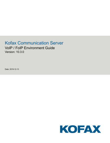
WWW. GOIP-PRO.RURoIP-102 User ManualII. Gift Box Check ListUpon unpacking the gift box,please check carefully that all items listed below areincluded.Please report to your supplier for any missing items immediately.1 PPT Adapter Cables1 AC/DC AdapterInput:110/220 VACOutput:12VDC,2A1 Main Unit1 Ethernet Cable
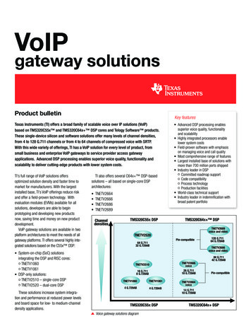
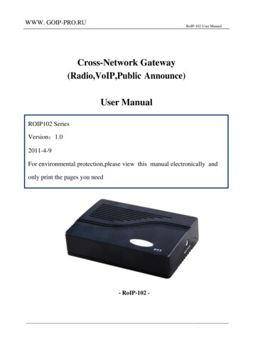
RoIP-102 User ManualIII. OverviewThe fundamental of RoIP Radio over IP technology is to convert the audio and PTT signals ina radio terminal into IP packets and then transmit the data via the IP networks.The challenge in thistechnology is to insure that the audio is transmitted in real time and the PTT control signal istransmitted immediately and reliably.The radio range is general limited by the restrictedtransmitting power,the antenna sensitivity,and other environmental factors.The success deploymentof this technology extends the coverage of a radio network without using expensive repeaters orlinks up multiple radio networks in the world.In addition,this technology can also link up the radioworld to the VoIP world and the cellular world easily.It truly makes voice communications acrossmultiple networks possible.RoIP 102 basic version is a more compact, more practical high-tech multiple network(Radio,Cellular,VoIP) equipment,which access to a group,no GSM module,simply complete theradio voice signals into IP signals,access to the Professdional Edition or Stardard Edition RoIP302M group,to achieve the client and the central station intercom communication.Also has a remotecontrol switch interface,which enables remote control.RoIP102 gateway can be installed in IP networks with intranet or internet connections viaADSL modem,Cable modem,or Local Area Network (LAN). The unique built-in DDNS client canhelp to simplify the installation and configuration without relying on a voice relay server in order toachieve interconnections among RoIP Series gateways.i. Basic link diagram
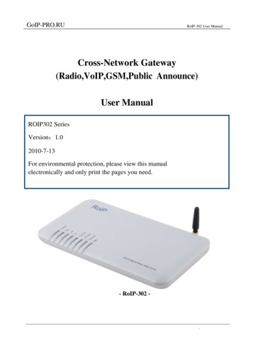
RoIP-102 User Manualii. Basic networking:multi-region over internetThe diagram above demonstrates A to use with the conference system RoIP302M as a centralswitching point,the other three regions using RoIP102.Through this link,ABCD four areas toachieve multi-region interconnections among RoIP Series gateways.iii. Model Nomenclature
RoIP-102 User ManualIV. Installationi. Back PanelLabel12NamePTT1Reote Switch335WANLANPowerDescription6-pin RJ11 port for PTT Adapter CableRelay switch with 220VAC input and 500 mAload current.10/100Base-T WAN connection for external10/100Base-T LAN connection12V 1Aii. LED IndicatorsLEDPowerRUNFunctionPwoerRoIP StatusLANLAN port statusPCPC port statusChannel 1Channel 1Tx/Rx statusDescriptionLights up when the power is connectedFlashes every 4 s indicates the device is not readyFlashes every 2 s indicates the device is readyLights up when the LAN port is connectedBlinks when there are data transmissions.Lights up when the PC port is connected.Blinks when there are data transmissions.Channel 1 is receiving / transmitting.
RoIP-102 User Manualiii. Channel Port Pin AssignmentThe channel port is 6-pin RJ-11 Socket1、 PTTOUT 2、GND3、Vin(RX) 4、Aout(TX)5、GND6、PTTINiv. PTT Adapter Cable wiring Diagramv. Switch PortThe built-in relay switch is connected to the middle two pinsof the RJ-11 socket.It acts as an ON/OFF switch for theexternal system connected.
RoIP-102 User Manualvi. Main Unit SetupConnect the Channel Port to a Radio Channel via the PPT Adapter Cabelprovided.Up to 1 channel is supported.Connect the WAN Port to a router,network switch,ADSL/Cabel Modem for accessan external network or the public network.Connect the Switch Port to an external system fro remote control.It can be used toswitch on and off a Public Announce (PA) system to instant broadcast.If the relayswitch is connected to high voltage load.The maximum rating for the internal relay is240VAC and 500 mA load current.Connect the LAN Port to a local PC or a local Ethernet network(LAN).This allowssharing the external network connected to the WAN Port with the localnetwork.However,the shared network is intended for configuration the device and isbest not used for high data traffics applications in order for the device to insure thebest voice quality.
RoIP-102 User ManualV. Default Factory SettingsThe table below shows the factory default settings.There are two way to reset to the factorydefault settings:i. Press the RESET switch for more than 15 seconds.ii. In the Configuration paga,select Tools and then Reset Config.ItemLogin IDLogin PasswordFactory Default SettingsadminadminWAN Port SettingLAN Port SettingPTT StateDHCP192.168.8.1“0”is activePTT maximum durationJitter Delay60 seconds60 millisecondsRangeProgrammable(16characters in the ASCIItable)“0” is active low“1” is active highLess than 600 seconds20-220 milliseconds
RoIP-102 User ManualVI. Device Configuration Via Built-in Web ServerThe built-in web server provides a comprehensive way to fully program the device manuallyi. Web Server LoginThere are two methods to access the built-in web server.Method 1 is to access the built-in web server via the LAN port.Connect a computer to the LANport of the RoIP102 and configure its IP to 192.168.8.x(x 2 to 254).Type the IP address 192.168.8.1in the address field of a web browser.The following login window is then displayed.Enter the User name and the password now.The user name for the administrative level is“admin” and the default password is “admin”.Please make sure to click on “Save Changes”after configuring the device.Method 2 is to access the built-in web server via the WAN port.The WAN port is set to DHCPmode as a default factory setting.When it is first connected to a network with a DHCP host,itobtains an IP address automatically from the host.In order to listen to the IP obtained,make a call tothe PSTN number.Once the call is answered,the device plays a voice prompt to ask forpassword.Dial “*00” and the device then reads out the WAN port IP address.Enter this IP in the address field of a web browser to get a login window as described inMethod 1.ii. Network settings:The network settings determine the work’s normal and stable of RoIP102.The network
RoIP-102 User Manualconnection’s optimal environment is private network with static IP route,followed by a dyamicpublic IP,such as ADSL,Radio and TV network,under the shared router IP network is relativelyunstable.If you must use the network shared line,strongly recommended the router set to DMZ toRoIP102 used IP.Setting up a network first used to confirm the network status,the general recommendation touse a fixed IP.Choose a fixed IP,WAN port on the network set the bar drop-down menu to select“Fixed IP”,in accordance with the network administrator to provide the IP,subnet mask,default route(gateway),DNS server,fill in the correct column in the network settings,Below:If you are using ADSL dial-up needed line,select the WAN port to PPPoE,the correspondingusename and password to complete the following chart:iii. DDNS Settings:If you use dynamic IP dees not depend on the exchange server,the user can use the DDNSservice.is provided free of charge’s dynamic IP address resolution services by DBLTEK.If you use dynamic IP does not depend on the exchange with server,the user can use the DDNSservice.DDNS service is a dynamic IP address resolution services is provided free of charge byDBLTEK.Use of the function,any RoIP device can be used body No as domain name.Through theDDNS server for the called party’s IP(both sides are using DDNS) setting mode as shownbelow.First select the DDNS,and then accordance with existing service providers addresses to fillout “DDNS server address” hk.ippcn.com,port:39980,update time:600 (second) and the deviceserial number(see bottom bar code paper machin SN: ).After using DDNS,the connected address will be
RoIP-102 User Manualwww.device serial number.com。
RoIP-102 User ManualVII. Call settingsi. Call Logic :RoIP can be connected between each other by SIP server as a proxy,can also be usedindependently by the way point to point.Because communication through the server will reduceefficiency and increase instability,it is strongly recommended to use the way point to pointnetwork.Therefore,this guide focuses on telling point is configured.ii. Log in and call logicBetween the different RoIP102 need to know each other’s IP and the attribution,so you need tologin.In the case of using the SIP server mode,all terminals connected in network must be log in tothe SIP server,Phone number is allocated by the SIP server.When using point to point connection,any RoIP102 as a Host to other terminal login,and thehost itself need to log into owns IP address.Host set up own’s phone number to be called by anotherterminal.The terminal need to log in to the host must have to set themselves phone number foridentification.iii. Call SettingsGroup 1 : is to set the group number.Each RoIP1102 need to set a number.Group SIP Number : is connected to the PPT group and the group’s unique idendifier,if using aSIP server provided by the server end.If use of point to point connections from their own layoutmanager.SIP Proxy : is the SIP service address.When using point to point connection,if RoIP102 as ahost,you need to fill out itselves IP address or DDNS address.If as a terminal,fill the host should belog in whos IP address or DDNS address.Auto Dial Number : is a appropriate number in the terminal it self to call the host automatically.
RoIP-102 User ManualWhen registered successful after start up,the terminal will automatically calls the numbercorresponding to a connection.iv. PTT Settings:PTT setting is to determine each PPT input and output Active level RMS value.PTT settingsdetermine each of the input and output RMS level,set “0” represents the effective interface potentialefficient PTT is low,is set to “1” indicates that the PTT interface is high potential effect.Fordifferent types of radio stations require accurate selection.PTT Output Expiry (second) is to protect the station will launch as a means for long,press thespecific needs of the settingv. Recorder SettingsRedorder Setting is set for each group recording audio server address need to recording,refer tothe recording software instructions.vi. Broadcasting SettingsBroadcasting Settings is actually seeting the password for Radio remote switch,when the switchis opened and not receiving the turn off password,then the Radio by the length of time to decidewhen to switch off automatically(time in seconds).Remote switch can only be control by a member of a group,so please select the which group isradio remote switch belonged to.
RoIP-102 User Manualviii. Public Announce (PA) SettingsThe RoIP302 provides a relay switch to control a PA system. When the RoIP302 receives thePA ON Password, it turns on the relay to activate the PA system. Audio is transmitted to the PAsystem at this time. When the RoIP302 receives the PA OFF Password, it turns off the relay todeactivate the PA system. The duration for the relay to be in the ON state is limited by the value setin the parameter PA ON Expiry. This mechanism shuts down the PA System automatically. ThePA Control Group defines which group has the control over the relay switch. Only the radioterminals in the group specified can broadcast to the PA System.All those terminal involved in the same group must use the same Announcecoding.
RoIP-102 User ManualVIII. Application ExamplesExample 1: Linking up two MOTO GM300 Radio terminals in peer-to-peer mode with twoRoIP102. The network access method is ADSL.Operating procedures:i. Connect the PTT Interface of the radio terminal (GM300) with the PTT Interface Cableas shown in the diagram below. Connect the RJ-11 plug of the PTT Interface Cable to PTT1port of the RoIP102.ii. Connect the RoIP302 LAN port to an Ethernet port of the ADSL Routeriii. Assign a fixed IP to the RoIP302 LAN port.This fixed IP must be in the same segment asthe LAN port of the ADSL Router.For example: if the LAN of the ADSL Router has an IP192.168.1.1, then the LAN port RoIP302 could be set to 192.168.1.101.iv. Configure the DMZ mode of the ADSL Router to fixed IP assigned to the RoIP302 LAN port.For DMZ configuration, please refer to the User Manual of the Router.v. Login to the RoIP Webpage and program the Network Settings as shown below.Pleasenote that the DNS addresses should be programmed as provided by from your local ISPNetwork settings:Domain name server address on the above map according to local service providers’ domainname server address (DNS) to be adjusted.
RoIP-102 User ManualGM300 in the PTT (COR) is low input and output RMS,so PTT settings are :A: set for the host,the number is set to 101,the body number is :ROIP2010060005,DDNS,and call setup is as follows:DDNS SettingsCall Settings:B: body number ROIP20100610006,the DDNS and call settings is as follows:DDNS Settings
RoIP-102 User Manualwhere xxx in www.xxx.com is host A inside the body number,such as ROIP20100610005Connected to only one radio in two side,so the group set as follows:Choose the best sound quality for Communications,so both sides have chosen alaw as speechcoding:Complete the connection,save the configuration after the restart RoIP102,open the Radio,the twoplace can Communications,After connecting through the respective end of the potentiometeradjustment adjust the volume to the best sound quality(DMZ’s Settings,please refer to the router manual).
RoIP-102 User ManualIX.Hardware Specificationsi.Physical and Operating Conditions- Dimension: 25 x 14 x 3 cm- Main Unit Net Wegith: 380 g- Storage Temperature: -40 C - 80 C- Operating Temperature: 0 C - 40 Cii.Core Design- CPU: ARM9- RAM: 16MB- FLASH: 4MB- DSP: 116 MHz, 16 Bit Busiii.T Interface- PTTIN Active Low: 0.7V (4.7KΩ load)- PTTIN Active High: 1.2V- PTTOUT High Output: 5V (4.7 KΩ load)- PTTOUT Low Output: 0V- APUT Output: 8Ω 750mW 5V P-P- AIN Input: 600Ω Internal Impedance, 0 – 0.6Vp-t-p- ADJOUT (on the Adapter Cable): 2KΩ Potentiometer- RAM: 16MBPTTIN Circuit:*Based on the circuit above,the PTT Input level is high when it is openended.
RoIP-102 User ManualPTTOUT Cicuit:iv. Network Port-Ethernet Port:10/100 Base-T-Standard Supported:IEEE802.1p-IP Standard:IPV4v. FirmwareItemOSIP Voice ProtocolNetwork ProtocolCodecsConfiguration GUIDescriptionRemarkLinuxVersion 2.6SIP 2.0Include SIP INFO extensionIP、TCP、UDP、HTTP、ICMP、DHCP CL & SRV、NTP、TFTP、ToS、telnetG.711 a&μ G.729A G.729AB G.723.1 GSMHtml XML2.0 JAVA
RoIP 102 basic version is a more compact, more practical high-tech multiple network (Radio,Cellular,VoIP) equipment,which access to a group,no GSM module,simply complete the radio voice signals into IP signals,access to the Professdional Edition or Stardard Edition RoIP 302M group,to achieve the client and the central station intercom .