Transcription
Agilent 4263B LCR MeterUser's GuideAgilent Part No. 04263-90022Printed in JAPANDecember 2000Fourth Edition
Documentation MapUser's Guide( This bookIs a handy reference to help you to get started using your 4263B, basic measurements andcommonly used features are explained.Operation Manual (Furnished with the 4263B.)Privides information on initial inspection, how to operate the 4263B, in-depth referenceinformation, general information, and meintenance information.In User's Guide.Chapter 1, Preparation for UseFor initial turn ON of the 4263BChapter 2, Operating the 4263BBasic Measurement operationGetting acquired with the 4263B : for beginnersHandy reference for measurement task : for all usersChapter 3, Measurement ExampleMeasurement examples for typical 4263B applicationsCapacitor measurementInductor measurementTransformer measurementIn the User's Guide, information on the following subjects is not discussed: Initial InspectionGPIB Remote ControlHandler Interface MaintenanceSpeci cationError MessagesFor detailed information on these subjects, refer to the Operation Manual.
Contents1.Preparation for Use2.Operating the 4263BIn This Chapter . . . . . . .Power Requirements . . . . .To Set Power LINE Voltage . .To Set Power LINE Frequency.1-11-11-11-3In This Chapter . . . . . . . . . . . . . . . . . . . . . . . . . . . . . . .Resetting 4263B to its Default Settings . . . . . . . . . . . . . . . . . . . .Connecting Test Fixture . . . . . . . . . . . . . . . . . . . . . . . . . . .Setting the Cable Length . . . . . . . . . . . . . . . . . . . . . . . . . . .Selectting the Measurement Parameter . . . . . . . . . . . . . . . . . . . .Setting the Test Signal Frequency . . . . . . . . . . . . . . . . . . . . . . .Setting the Test Signal Level . . . . . . . . . . . . . . . . . . . . . . . . .Setting the DC Bias Source Voltage . . . . . . . . . . . . . . . . . . . . . .Selecting the Measurement Time Mode . . . . . . . . . . . . . . . . . . . .Setting the Averaging Rate . . . . . . . . . . . . . . . . . . . . . . . . . .Selecting the Measurement Range . . . . . . . . . . . . . . . . . . . . . . .Auto Range mode Automatically Selecting the Optimum Measurement RangeHold Range mode Selecting the Measurement Range of Your Choice . . . . .Selecting the Trigger Mode . . . . . . . . . . . . . . . . . . . . . . . . . .Setting the Trigger Delay Time . . . . . . . . . . . . . . . . . . . . . . . .Performing the OPEN Correction Canceling the stray admittance in parallel with the DUT . . . . . . . . .Performing the SHORT Correction Canceling the residual impedance in series with the DUT . . . . . . . . .Using the Comparator Function . . . . . . . . . . . . . . . . . . . . . . . .Setting the Limit Values . . . . . . . . . . . . . . . . . . . . . . . . . .Starting the Sort . . . . . . . . . . . . . . . . . . . . . . . . . . . . . .Using the Contact Check Function Monitoring the connection of test electrodes and DUT . . . . . . . . . .Using the Deviation Measurement Function . . . . . . . . . . . . . . . . . .Setting the Deviation Reference Values . . . . . . . . . . . . . . . . . . .Selecting the Deviation Mode . . . . . . . . . . . . . . . . . . . . . . . .Selecting the Display Mode . . . . . . . . . . . . . . . . . . . . . . . . . .Using the Level Monitor Function . . . . . . . . . . . . . . . . . . . . . . .Selecting the Beeper Mode . . . . . . . . . . . . . . . . . . . . . . . . . .Setting the Printer Printing the measurement data . . . . . . . . . . . . . .Connecting the DUT . . . . . . . . . . . . . . . . . . . . . . . . . . . . .Applying the DC Bias . . . . . . . . . . . . . . . . . . . . . . . . . . . .Making a Measurement . . . . . . . . . . . . . . . . . . . . . . . . . . . .Veri cation of Current Settings . . . . . . . . . . . . . . . . . . . . . . . .If You Have a Problem . . . . . . . . . . . . . . . . . . . . . . . . . . . .Reference . . . . . . . . . . . . . . . . . . . . . . . . . . . . . . . . . .Default Settings . . . . . . . . . . . . . . . . . . . . . . . . . . . . . .Measurement Parameters . . . . . . . . . . . . . . . . . . . . . . . . . 2-172-172-172-182-192-192-19Contents-1
Accessories Available . . . . . . .16064B LED Display/Trigger BoxTest Fixtures and Test Leads . .Accessories List . . . . . . . .Measurement Range Setting . . .Other Topics . . . . . . . . . . . .3.2-202-202-202-222-232-23In This Chapter . . . . . . . . . . . . . . . . . . . .Electrolytic Capacitor Measurement For High CapacitanceDUT . . . . . . . . . . . . . . . . . . . . . . . .Requirements . . . . . . . . . . . . . . . . . . . .Measurement Setup . . . . . . . . . . . . . . . . .Measurement Procedure . . . . . . . . . . . . . . .For More Information . . . . . . . . . . . . . . . .Inductor Measurement Versatile measurement parametersDUT . . . . . . . . . . . . . . . . . . . . . . . .Requirements . . . . . . . . . . . . . . . . . . . .Test Fixture . . . . . . . . . . . . . . . . . . . . .Measurement Setup . . . . . . . . . . . . . . . . .Measurement Procedure . . . . . . . . . . . . . . .For More Information . . . . . . . . . . . . . . . .Transformer Measurement (Option 001 Only) . . . . . .DUT . . . . . . . . . . . . . . . . . . . . . . . .Requirements . . . . . . . . . . . . . . . . . . . .Measurement Setup . . . . . . . . . . . . . . . . .Measurement Procedure . . . . . . . . . . . . . . .For More Information . . . . . . . . . . . . . . . 113-113-113-113-14Measurement ExamplesContents-2
Figures2-1. Connecting a Test Fixture . . . . . . . . . . . . . . . . . . . . . . . . .2-2. Printer Output . . . . . . . . . . . . . . . . . . . . . . . . . . . . . . .2-3. Connecting the DUT . . . . . . . . . . . . . . . . . . . . . . . . . . . .2-22-162-16Tables1-1. Line Voltage Selection . . . . . . . . . . . . . . . . . . . . . . . . . . .1-2Contents-3
1Preparation for UseIn This ChapterFirst you must set the 4263B to match the available power LINE voltage, before turning the4263B ON.If the 4263B's power LINE voltage and frequency are properly set and ready to use, you canskip this chapter.Power RequirementsThe 4263B's power source requirements are as follows:LINE Voltage : 100 / 120 / 220 / 240 V ac (610%)LINE Frequency : 47 to 66 HzPower Consumption : 45 VA maximumTo Set Power LINE Voltage1. Con rm that the power cable is disconnected.2. Slide the LINE Voltage selector on the rear panel to match the ac LINE voltage which willbe used (see Table 1-1).Preparation for Use1-1
4263BTable 1-1. Line Voltage Selection1-2Voltage SelectorLine VoltageRequired Fuse(a) 115 V100 / 120 VT 0.5 A 250 V(Agilent part number 2110-0202)(b) 230 V220 / 240 VT 0.25 A 250 V(Agilent part number 2110-0201)Preparation for Use
4263BTo Set Power LINE FrequencyIn this manual, the BLUE shift key is expressed asNote, the top of the key isnot labeled \blue".1. Connect the power cable to the power cord receptacle on the rear panel.2. Push the LINE switch in and the 4263B will emit a beep when it turns ON, and the selftests will be performed. (If any message is displayed, see \Error Messages" at the back ofOperation manual.) The 4263B will be ready for operation after a message like the followingis displayed.3. Press4. Press. The following con guration menu is displayed.until Line blinks, then press.A blinking item means that it is currently selected.5. If the setting does not match the ac line frequency, pressto toggle the settingbetween 50 HZ and 60 HZ.to set the line frequency.6. PressPreparation for Use1-3
4263B7. Exit the con gration menu by selecting Exit.Note1-4The power line frequency setting is stored and is not changed after reset orpower-o . Once you set it, you do not need to set the line frequency again aslong as the same power line frequency is being used.Preparation for Use
2Operating the 4263BIn This ChapterBasic operation of the 4263B is explained.Operating the 4263B2-1
4263BResetting 4263B to its Default Settings1. Pressto select the reset menu.2. Select Yes usingor, and press.The 4263B will be reset to its default settings. For more information about the default settings,see \Default Settings" later in this chapter.Connecting Test FixtureConnect the test xture to the UNKNOWN terminals as follows:Figure 2-1. Connecting a Test FixtureSee information on available test xtures, \Accessories Available" later in this chapter.2-2Operating the 4263B
4263BSetting the Cable LengthThe cable length correction function cancels the phase shift error caused by the cable length.When using the Agilent test leads, perform the cable length correction as follows:1. Press. Cable lengths 0 m, 1 m, 2 m, and 4 m will be displayed.The blinking cable length is the current setting.2. Select the desired cable length usingor. To determine which length you shouldselect, see \Accessories Available" later in this chapter.3. Press.Selectting the Measurement Parameter1. Press. The primary measurement parameters are displayed.2. Select the desired primary parameter usingor, and press.3. Then the secondary parameters are displayed in the same manner as above.The secondary parameters which can be selected di er depending on the primary parameter.Refer to \Measurement Parameters" later in this chapter.4. Select the desired secondary parameter usingor, and press.Operating the 4263B2-3
4263BSetting the Test Signal FrequencyPress. The test signal frequency selection menu is displayed.Select the desired frequency usingor, and pressYou can also select the test signal frequency by pressing.until the desired frequency isdisplayed.Note that the 10 kHz and 20 kHz (Option 002 only) test frequency are not available when thecable length setting is 4 m, and the 100 kHz test frequency is not available when the cablelength setting is 2 m or 4 m.Setting the Test Signal Level1. Press. The test signal level selection menu is displayed.2. Enter the desired value using the numeric keys and the engineering keyexample, to set the level to 245 mV, press( or press).You can also set the value using3. Press2-4to set the test signal level.Operating the 4263Bor. For.
4263BSetting the DC Bias Source Voltage1. Press. The DC bias setting menu is displayed.2. Select the desired DC bias voltage value usingor, and press.Now the DC bias source is selected. For how to apply the DC bias voltage, see \Applying theDC Bias", later in this chapter.Selecting the Measurement Time Mode1. Pressto select the measurement time mode (Short, Med or Long). The Meas Timeannunciator ( 9 ) displays the measurement time setting.Setting the Averaging Rate1. Press.2. Enter the averaging rate using the numeric keys. You can enter integer values from 1 to256. Also, you can increase or decrease the value usingor.3. Pressto set the value and to exit.Operating the 4263B2-5
4263BSelecting the Measurement RangeAuto Range mode Automatically Selecting the Optimum Measurement RangePress. The 4263B's range mode is changed from \Hold" to \Auto", or from \Auto" to\Hold". When the Hold Range annunciator( 9 ) is OFF, the 4263B is set to the auto range mode.Hold Range mode Selecting the Measurement Range of Your Choice1. Press2. Press.oruntil the desired range is displayed. Or, input the impedance value tobe measured using the numeric keys and the engineering key. The 4263B will selectthe optimum measurement range setting.3. Press. to set the measurement range.The available ranges are 0.1 , 1 , 10 , 100 , 1 k , 10 k , 100 k , and 1 M . To determinewhich measurement range you should select, see \Measurement Range Setting" later in thischapter.2-6Operating the 4263B
4263BSelecting the Trigger ModePressuntil the Trigger annunciator ( 9 ) points to the desired trigger mode (Int, Man orExt).To trigger a measurement in each mode, see \Making a Measurement" later in this chapter.Setting the Trigger Delay Time1. Press.2. Enter the desired trigger delay time using the numeric keys. (For example, to set 0.5 sec,press.) You can set the trigger delay time from 0.000 sec to 9.999 sec.You can also set the trigger delay time using3. Pressor;.Operating the 4263B2-7
4263BPerforming the OPEN Correction Canceling the stray admittance in parallel with the DUT1. Con rm that the test xture is connected to the UNKNOWN terminals without a DUTconnected.2. Press. The OPEN correction menu is displayed.Pressoruntil Openmeas blinks, and press. The OPEN correction isperformed. During that time, the following message is displayed.After a while, the 4263B completes OPEN correction with the message Open CorrectionComplete, and returns to the measurement state.If \Out Of Limit", a WARNING message, is displayed, the OPEN admittance is so high that itwould be unsuitable for OPEN correction data. This is only a WARNING, the OPEN correctiondata will still be used. However, you must verify the test xture connection to the UNKNOWNterminals and the procedure used to perform the OPEN correction.Verify that the test xture is correctly connected to the UNKNOWN terminal.Verify that nothing is connected to the test xture's test electrode.Perform OPEN correction again after verifying the above items.2-8Operating the 4263B
4263BPerforming the SHORT Correction Canceling the residual impedance in series with the DUT1. Con gure the test electrodes in a SHORT con guration by connecting the High and Lowelectrodes to each other or by connecting a shorting bar to the test xture.2. Press. The SHORT correction menu is displayed.3. Pressoruntil Shortmeas blinks, and press. SHORT correction isperformed. During that time, the following message is displayed.After a while, the 4263B completes SHORT correction with the message Short CorrectionComplete, and returns to the measurement state.If \Out Of Limit", a WARNING message, is displayed, the SHORT impedance is so high thatit would be unsuitable for SHORT correction data. This is only a WARNING, the SHORTcorrection data will still be used. However, you must verify the test xture connection to theUNKNOWN terminals and the procedure used to perform the SHORT correction.Verify that the test xture is correctly connected to the UNKNOWN terminal.Verify that the test xture's test electrodes are correctly shorted.Perform SHORT correction again after verifying the above items.Operating the 4263B2-9
4263BUsing the Comparator FunctionSetting the Limit Values1. Pressto set the lower limit of the primary parameter, andlimit. Pressto set the higherto set the lower limit of the secondary parameter, andto set the higher limit.For example, the following menu is displayed when2. Enter the value using the numeric keys, then pressis pressed.to set the value. You can set thevalue from 0999.99210 to 999.99210 .1414Starting the Sort3. Press. The Comptr On annunciator( 9 ) turns ON, and the comparator function isturned ON.The sorting results are HIGH, IN, and LOW.Where,HIGHgreater than the higher limitINbetween the higher and lower limitsLOWless than the lower limitThe 4263B shows the comparison results using the display, beeper, printer, and16064B LED Display/Trigger Box.For result output to the display, see \Selecting the Display Mode" later in this chapter.For result output to the beeper, see \Selecting the Beeper Mode" later in this chapter.For result output to the printer, see \Setting the Printer Printing the measurement data"later in this chapter.For result output to the 16064B, see \Accessories Available" later in this chapter.2-10Operating the 4263B
4263BUsing the Contact Check Function Monitoring the connection of test electrodes and DUTPress, and the Cont Chk annunciator( 9 ) turns ON.When the contact check result is Fail, the 4263B displays N.C. (No-Contact).Using the Deviation Measurement FunctionSetting the Deviation Reference Values1. PressPress.oruntil 1RefEnt blinks, and press.2. You can now input the primary parameter's reference value. Enter the reference value withthe numeric keys, and pressto set the value.3. Then the 4263B displays the menu for setting the secondary parameter's reference value.Enter the reference value with the numeric keys, and pressto set the value.Operating the 4263B2-11
4263BSelecting the Deviation Mode4. The primary parameter's mode can be set by selecting Pri and pressing.Measured value0Reference1%(Measured value0Reference)/Reference 2100 %OffTurning the deviation mode OFF.Select the deviation measurement mode withor, and press.1ABS5. The secondary parameter's mode can be set by selecting Sec and pressingmanner as the primary. Select the desired mode with2-12Operating the 4263Bor, and pressin the same.
4263BSelecting the Display ModePressPressorto select Data, Cmprtr, Digit or Off, and press.The Measurement Display mode (Data) shows the measurement data:The Comparison Display mode (Cmprtr) shows the comparison results:When Digit is selected, the following menu is displayed, allowing you to set the number ofdigits displayed for the measured value.When Off is selected, the 4263B will not display the measurement results (Display OFFmode).Operating the 4263B2-13
4263BUsing the Level Monitor Function1. Press, and the following menu is displayed.2. Select Off, Imon, Vmon or Both using.When Imon is selected, the 4263B will monitor the actual signal current owing throughthe DUT.When Vmon is selected, the 4263B will monitor the actuall signal voltage across the DUT.When Both is selected, the 4263B will monitor both current and voltage.When Off is selected, the level monitor function is turned OFF.3. Press.You can see the level monitor values on the LCD display by pressing2-14Operating the 4263Bseveral times;.
4263BSelecting the Beeper ModeTo change the beeper mode for the comparator result reporting:1. Press.2. Select Beep usingor3. Select the beep mode using4. Select Exit usingor, and pressor., and press, and press.Setting the Printer Printing the measurement data1.2.3.4.Use an GPIB compatible printer, set to the Listen Always mode.Connect the printer to the 4263B's GPIB port on the rear panel.Turn the printer ON.Set the 4263B to talk only mode (Set the 4263B's GPIB address to 31).a. Press. Or pressorto change the value.b. Press. The Talk Only annunciator( 9 ) turns ON, and the printer begins printing themeasurement data.Operating the 4263B2-15
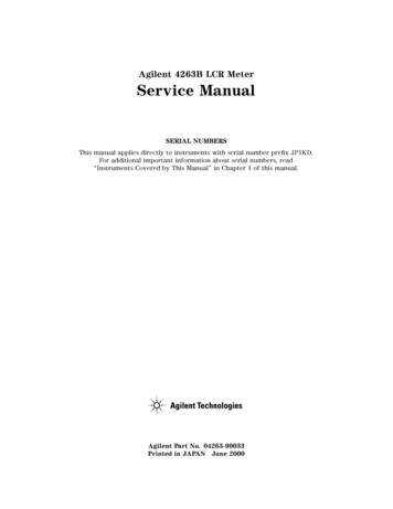
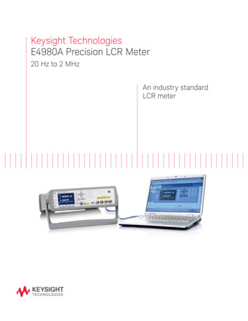
4263BFigure 2-2. Printer OutputWhen you want to disable printing, change the GPIB address to an address other than 31 (forexample, 17, which is the default setting).Connecting the DUTConnect the DUT to the test electrodes.Figure 2-3. Connecting the DUT2-16Operating the 4263B
4263BApplying the DC BiasPressto apply the DC bias. The DC Bias ON/OFF indicator is ON.(Pressagain to turn OFF the DC bias. The DC Bias ON/OFF indicator is OFF.)Making a MeasurementIn the internal trigger mode The 4263B makes continuous free-running measurements.In the manual trigger mode Presswhen you want to trigger a measurement.In the external trigger mode Connect the external trigger source to the EXT TRIGGERterminal on the 4263B's rear panel, and apply a TTL level trigger signal to trigger ameasurement. (For details, see Operation Manual .)Note that it must be set to the external trigger mode to trigger from an external handler orthe 16064B LED Display/Trigger Box.Veri cation of Current SettingsPress.The display on the right side of the LCD changes, and each timeis pressed, the nextcurrent setting is displayed.1. Test signal frequency and Test signal level2. DC bias setting and Averaging rate3. Trigger delay time and Cable length4. Comparator limits for primary parameter5. Comparator limits for secondary parameter6. Level monitor valueOperating the 4263B2-17
4263BIf You Have a ProblemIf any of the problems listed below occur, follow the instructions described.If you nd yourself lost when operating the 4263B, you can get back on track by:To return to the measurement mode, pressseveral times.To return to the default settings, press. (If the reset not accepted, con rm thatthe Key Lock annunciator is turned ON. See next.)If the 4263B does not accept key input:Check whether or not the Key Lock annunciator( 9 ) is ON. If so,Press. The Key Lock annunciator( 9 ) turns OFF and the front-panel keys areunlocked.Check that the 16064B LED display/trigger box is connected to the 4263B and it is set tolock out the keys. If so, unlock the keys from the 16064B.If the 4263B does not display measurement results:The display mode is set to the Display OFF mode.1. If the 4263B is in the key lockout mode, cancel the key lockout mode. (See previousdescription.)2. Pressto change the display mode to a mode other than Display OFF.If ------ or OVLD is displayed:The measurement result is out of the measurable range. Check the DUT and make sure themeasurement range is properly set.2-18Operating the 4263B
4263BReferenceDefault Settings Frequency Test voltage level DC Bias DC Bias source Measurement parameter Deviation measurement Measurement range Measurement time Averaging rate Trigger mode::::::::::1 kHz1 VrmsOFF0VCp-DOFFAutoMEDium1Internal Trigger delay: 0 ms Comparator: OFF Contact check: OFF Display mode: Measurement mode Beep mode: FAIL mode Cable length:0m Display digits:5 Level monitor: OFF OPEN/SHORT correction data is clearedMeasurement ParametersPrimarySecondary Parameters WhichParameterMay Be Selected For Th isPrimary ParameterZYRGCpCsLpLsL2 XBD Q G RpD Q RsD Q G Rp RdcD Q Rs RdcN 1/N M R2Z : impedance ( absolute value )Y : admittance ( absolute value ) : phase angleR : resistanceLs : equivalent series inductanceLp : equivalent parallel inductanceCs : equivalent series capacitanceCp : equivalent parallel capacitanceQ : quality factorD : dissipation FactorG : conductanceX : reactanceB : susceptanceRp : equivalent parallel resistanceRs : equivalent series resistanceRdc :dc resistanceN : turns ratio of transformer1M :mutual inductance1L2 : inductance1R2 : dc resistance11 This para meter is measured using the transformer measurement con guration (two-terminal measurementcon guration).Operating the 4263B2-19
4263BNotePrimary parameter L2 and secondary parameters Rdc, N, M, and R2 can onlybe used with Option 001 (N / M / DCR measurement function addition). Theseparameters are not displayed on the menu if the 4263B is not equipped withOption 001.To measure the primary parameter L2, the transformer measurementcon guration is required. So use the 16060A Transformer Test Fixture.Accessories Available16064B LED Display/Trigger BoxThe 16064B LED Display/Trigger Box triggers a measurement when its trigger key is pressed,and displays the contact check and comparison results using LEDs. It allows you to manuallyoperate the comparator function of the 4263B.Test Fixtures and Test LeadsFor measurement versatility, various types of test xtures and test leads are available for the4263B. In this section, main test xtures and test leads are described using gures. When usingthese test xtures and test leads, set the 4263B to the corresponding cable length of the testxture or test leads being used.2-20Operating the 4263B
4263BOperating the 4263B2-21
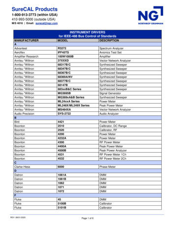
4263BAccessories 16089D16089E16092A116093A116093B116094A1 451B16452A16064B,Test Fixture (For SMD or Chip type DUT)Test Fixture (For Axial or Radial DUT)Test Fixture (For Axial or Radial DUT)HF Test Fixture (For Axial or Radial DUT)Test Fixture (For Axial or Radial DUT)Test Leads (1 m, BNC)Test Leads (1 m, SMC)Test Leads (2 m, BNC)Test Leads (4 m, BNC)Transformer Test FixtureExternal Bias Test FixtureExternal Bias AdapterTerminal Adapter: Converts 4 terminal pair connector to APC7 connector.Kelvin Clip Leads (1 m, two large clips)Kelvin Clip Leads (1 m, two medium clips)Kelvin Clip Leads (1 m, two IC clips)Alligator Clip Leads (1 m, four medium clips)Kelvin Clip Leads (1 m, two large clips)RF Spring Clip: Axial Radial and SMDRF Two-Terminal Binding PostRF Three-Terminal Binding PostRF Probe Tip/AdapterLF Probe AdapterSide Electrode SMD Test FixtureParallel Electrode SMD Test FixtureSmall Side Electrode SMD Test FixtureWide Temperature SMD Test Fixture50 /4-Term Converter 100Hz-10MHzTest Fixture (For SMD or Chip type DUT)Dielectric Test FixtureMagnetic Test FixtureLED Display/Trigger Box (with GO/NO-GO display and trigger button)1 16085B adapter required.2 Cables adapted to APC7 on each end required.3 Don't connect ground-lead to 4263B.Note2-22There is some possibility that available accessories are changed. Refer to latestaccessories catalogue about the latest information.Operating the 4263B
4263BMeasurement Range SettingRange Setting0.111101001k10 k2100 k1M2Optimum Measurement RangejZj 100 m100 m jZj 11 jZj 1010 jZj 1 k1 k jZj 10 k10 k jZj 100 k100 k jZj 1 M1 M jZj 10 M1 This range is available when the test level settings is higher than315 mV.2 This range is not available for the 100 kHz test frequencysetting.Other TopicsFor details on these functions, see the Operation Manual.Initial Inspection Chapter 1 of the Operation ManualLoad correction Chapter 1, Chapter 3 and Chapter 7 of the Operation ManualKey Lock Function Chapter 2 and Chapter 3 of the Operation ManualGPIB Chapter 4 and Chapter 5 of the Operation ManualHandler Interface Chapter 3, Chapter 6, and Appendix B of the Operation ManualSave / Recall Chapter 2 and Chapter 3 of the Operation ManualBackup Function Chapter 3 of the Operation ManualSpeci cation Chapter 8 of the Operation ManualMaintenance Chapter 9 of the Operation ManualError Messages \Error Messages" in back of the Operation ManualOperating the 4263B2-23
3Measurement ExamplesIn This ChapterThis chapter provides the typical measurement examplesMeasurement Examples3-1
Electrolytic Capacitor Measurement For High Capacitance4263BThe 4263B's measurement accuracy and wide measurement range are the right tools to makeprecise measurements of electrolytic capacitor parameters.Electrolytic capacitors are generally high capacitance, so their impedance is low. The 4263B hasthe 100 m measurement range, and keeps its high measurement accuracy when measuring lowimpedance. For example, the 4263B measures an aluminum electrolytic capacitor, 22,000 F, atthe test frequency of 120 Hz, with about 0.5 % accuracy. You can try this measurement usingthe following procedure.DUTAluminum electrolytic capacitor ( 22,000 F 6 20 % )RequirementsTest Fixture : 16089B Kelvin Clip LeadsMeasurement SetupMeasurement parameterTest frequencyTest signal level: Cs-D1: 120 Hz: 1 Vrms21 For high capacitance measurement, equivalent seriesparameter Cs-D is commonly used.2 Even though LVL:1 Vrms is set, less than 0.5Vrmswhich is maximum appliable volatge for testingelectrolytic capacitors in accordance to JIS standard,will be applied to the Aluminum electrolytic capacitorunder test.Measurement Procedure1. Reset the 4263B.a. Pressb. Press3-2.until Yes blinks, and pressMeasurement Examples.
4263B2. Connect test xture to the UNKNOWN terminals as follows.3. Set the cable length to 1 m.a. Press.b. Select 1 m usingor, and press.4. Set measurement parameter to Cs-D.a. Press, and the following menu is displayed.b. Select Cs usingc. Select D usingoror, and press, and press.Measurement Examples3-3
4263B5. Set the test frequency to 120 Hz.Press.Pressorto set the frequency to 120Hz, and press.6. Perform the OPEN correction.a. Separate the test lead clips ( Nothing must be connected to the test lead clips).b. Pressand the following menu is displayed.c. Select OpenMeas usingor, and press.After a while, the OPEN correction is completed. (If Out OfLimit is displayed, see \Performing the OPEN Correction Canceling the stray admittance in parallel with the DUT" in Chapter 2.)7. Perform the SHORT correction.a. Short the electrodes of the test xture as shown in the following gure.3-4Measurement Examples
4263Bb. Press, and the following menu is displayed.c. Select ShortMeas usingor, and press.After a while, the SHORT correction is completed.(If Out OfLimit is displayed, see \Performing the SHORT Correction Canceling the residual impedance in series with the DUT" in Chapter 2.)8. Connect the DUT to the test xture, and the measurement result will be displayed.For More InformationTo apply the DC bias See \Setting the DC Bias Source Voltage" in Chapter 2.To print out the measurement result See \Setting the Printer Printing the measurementdata" in Chapter 2Measurement Examples3-5
4263BInductor Measurement Versatile measurement parametersThe 4263B o ers many kinds of measurement parameters for LCR measurement. In addition tothese parameters, Option 001 adds ability to make turns ratio (N), mutual inductance (M), DCresistance (DCR) measurements.This example shows a basic measurement for an inductor, and its DCR. You can measure bothinductance and DCR without resetting the measurement con guration.DUTCoil ( 220 H 6 5 % @ 100kHz )RequirementsTest Fixture : 16047ATest Fixture16047AMeasurement SetupMeasurement parameterTest frequencyTest signal level: Lp-Q and Lp-Rdc: 100 kHz: 100 mVrmsMeasurement Procedure1. Reset the 4263B.a. Pressb. Press.until Yes blinks, and press.2. Connect the test xture to the UNKNOWN terminals.3-6Measurement Examples
4263B3. Select measurement parameter Lp-Q.a. Pressand the following menu is display
Agilent 4263B LCR Meter User's Guide Agilent P art No . 04263-90022 Printed in JAP AN December 2000 F ourth Edition. Documentation Map User's Guide ( This book Is a handy reference to help you to get started using your 4263B , basic measurements and commonly used features are explained.