Transcription
Agilent U1731B/U1732BDual Display HandheldLCR MeterUser’s and Service GuideAgilent Technologies
Notices Agilent Technologies, Inc. 2009 – 2012WarrantyNo part of this manual may be reproduced inany form or by any means (including electronic storage and retrieval or translationinto a foreign language) without prior agreement and written consent from AgilentTechnologies, Inc. as governed by UnitedStates and international copyright laws.The material contained in this document is provided “as is,” and is subject to being changed, without notice,in future editions. Further, to the maximum extent permitted by applicablelaw, Agilent disclaims all warranties,either express or implied, with regardto this manual and any informationcontained herein, including but notlimited to the implied warranties ofmerchantability and fitness for a particular purpose. Agilent shall not beliable for errors or for incidental orconsequential damages in connection with the furnishing, use, or performance of this document or of anyinformation contained herein. ShouldAgilent and the user have a separatewritten agreement with warrantyterms covering the material in thisdocument that conflict with theseterms, the warranty terms in the separate agreement shall control.Manual Part NumberU1731-90059EditionThird Edition, March 21, 2012Printed in MalaysiaAgilent Technologies, Inc.5301 Stevens Creek Blvd.Santa Clara, CA 95051 USASafety NoticesTechnology LicensesThe hardware and/or software described inthis document are furnished under a licenseand may be used or copied only in accordance with the terms of such license.Restricted Rights LegendCAUTIONA CAUTION notice denotes a hazard. It calls attention to an operating procedure, practice, or the likethat, if not correctly performed oradhered to, could result in damageto the product or loss of importantdata. Do not proceed beyond aCAUTION notice until the indicatedconditions are fully understood andmet.WA R N I N GA WARNING notice denotes ahazard. It calls attention to anoperating procedure, practice, orthe like that, if not correctly performed or adhered to, could resultin personal injury or death. Do notproceed beyond a WARNINGnotice until the indicated conditions are fully understood andmet.U.S. Government Restricted Rights. Software and technical data rights granted tothe federal government include only thoserights customarily provided to end user customers. Agilent provides this customarycommercial license in Software and technical data pursuant to FAR 12.211 (TechnicalData) and 12.212 (Computer Software) and,for the Department of Defense, DFARS252.227-7015 (Technical Data - CommercialItems) and DFARS 227.7202-3 (Rights inCommercial Computer Software or Computer Software Documentation).IIU1731B/U1732B User’s and Service Guide
Safety SymbolsThe following symbols on the instrument and in the documentationindicate precautions that must be taken to maintain safe operation of theinstrument.Direct currentOff (supply)Alternating currentOn (supply)Both direct and alternatingcurrentEquipment protected throughoutby double insulation or reinforcedinsulation.Three-phase alternating currentCaution: risk of electric shock.Earth (ground) terminalCaution: risk of danger (refer tothis manual for specific Warningor Caution information.Protective conductor terminalCaution: hot surface.Frame or chassis terminalOut position of a bi-stable pushcontrol.EquipotentialityIn position of a bi-stable pushcontrol.U1731B/U1732B User’s and Service GuideIII
Regulatory MarkingsThe CE mark is a registeredtrademark of the EuropeanCommunity. This CE mark showsthat the product complies with allthe relevant European LegalDirectives.The C-tick mark is a registeredtrademark of the SpectrumManagement Agency of Australia. Thissignifies compliance with the AustraliaEMC Framework regulations under theterms of the Radio Communication Actof 1992.ICES/NMB-001 indicates that thisISM device complies with CanadianICES-001.This instrument complies with theWEEE Directive (2002/96/EC) markingrequirement. This affixed product labelindicates that you must not discard thiselectrical/electronic product indomestic household waste.Waste Electrical and Electronic Equipment (WEEE) Directive2002/96/ECThis instrument complies with the WEEE Directive (2002/96/EC) markingrequirement. This affixed product label indicates that you must notdiscard this electrical/electronic product in domestic household waste.Product Category:With reference to the equipment types in the WEEE directive Annex 1,this instrument is classified as a “Monitoring and Control Instrument”product. The affixed product label is shown as below:Do not dispose in domestic household wasteTo return this unwanted instrument, contact your nearest Agilent office,or visit:www.agilent.com/environment/productfor more information.IVU1731B/U1732B User’s and Service Guide
General Safety InformationThe following general safety precautions must be observed during allphases of operation, service, and repair of this instrument. Failure tocomply with these precautions or with specific warnings elsewhere inthis manual violates safety standards for design, manufacture, andintended use of the instrument. Agilent Technologies assumes no liabilityfor the customer’s failure to comply with these requirements.WA R N I N G CAUTION This meter is for indoor use at an altitude of up to 2,000 m.The warnings and precautions should be read and well understoodbefore the meter is used.Use this meter only as specified in this manual; otherwise, theprotection provided by the meter may be impaired.When measuring in-circuit components, first de-energize thecircuits before connecting them to the test leads.Discharge the capacitor before testing.The meter is safety-certified in compliance with IEC 61010-1.Use the meter only as specified in this manual. Otherwise, theprotection provided by the meter may be impaired.The power for the meter is supplied with a single standard 9 Vbattery. Line operation is also possible using a 12 VAC to DC adaptor.If a power adaptor is selected, please be sure to meet the safetyrequirements of a relevant IEC standard.Ensure proper insertion of the battery in the LCR meter, and follow thecorrect polarity.U1731B/U1732B User’s and Service GuideV
Environmental ConditionsThis instrument is designed for indoor use in areas with low condensationand to be used with standard or compatible test probes. Table 1 showsgeneral environment requirements.Table 1VIEnvironment requirementsEnvironment ConditionsRequirementsOperating environment0 C to 40 C; 0 – 70% R.H.Storage humidity0 – 80% R.H. non condensingStorage environment–20 C to 50 C; 0 – 80% R.H.Altitude0 – 2,000 metersPollution degreePollution degree 2U1731B/U1732B User’s and Service Guide
CAUTIONThe U1731B/U1732B dual display handheld LCR meter complies withthe following safety and EMC requirements: CAUTIONIEC 61010-1:2001/EN 61010-1:2001 (2nd Edition)CISPR 11:2003 A1:2004IEC 61000-4-2:1995 A1:1998 A2:2000IEC 61000-4-3:2006IEC 61000-4-4:2004IEC 61000-4-5:2005IEC 61000-4-6:2003 A1:2004 A2:2006IEC 61000-4-11:2004Canada: ICES/NMB-001:2004Australia/New Zealand: AS/NZS CISPR11:2004Degradation of some product specifications can occur in the presenceof ambient electromagnetic (EM) fields and noise that affects theproduct's power line, communication, or I/O cables. The productself-recovers and operates to all specifications when: the source of the ambient EM field and noise is removed, the product is protected from the ambient EM field, or the product cabling is shielded from the ambient EM noise.U1731B/U1732B User’s and Service GuideVII
Declaration of Conformity (DoC)The Declaration of Conformity (DoC) for this instrument is available on the Website. You can search the DoC by its product model or om/DoC/search.htmNOTEVIIIIf you are unable to search for the respective DoC, please contact your localAgilent representative.U1731B/U1732B User’s and Service Guide
In This Guide 1Getting Started Chapter 1 introduces key features and steps to get startedwith a U1731B/U1732B dual display handheld LCR meter. This chapter alsoguides you through the basics of the front panel operations.2Features and Functions Chapter 2 explains how to set up connections toperform meter measurements. It also describes the features and functions thatare available in the U1731B/U1732B dual display handheld LCR meter instep-by-step instructions.3Service and Maintenance Chapter 3 explains the services and maintenanceprocedures for the U1731B/U1732B dual display handheld LCR meter.4SpecificationsChapter 4 lists the specifications and characteristics of theU1731B/U1732B dual display handheld LCR meter.U1731B/U1732B User’s and Service GuideIX
XU1731B/U1732B User’s and Service Guide
ContentsContents1 Getting StartedIntroduction 2Checking the Shipping Contents 3The Front Panel at a Glance 4Display Annunciators 5The Keypad at a Glance 7The Input Terminal at a Glance 82 Features and FunctionsInductance Measurement 10Capacitance Measurement 11Resistance Measurement 12Data Hold 13Static Recording 13Dissipation Factor/Quality Factor/Phase Angle 13Test Frequency 14LCR Function Selector 14Relative 14Tolerance 15Auto/Manual Range 15Automatic Fuse Detection 16Parallel/Series Mode 16CAL Function 17Enable/Disable Auto Power-Off 19Low Battery Indication 19Backlit Display (Only Available for U1732B) 19Communication (Optional Accessories) 203 Service and MaintenanceService 22Battery Replacement 22U1731B/U1732B User’s and Service GuideXI
ContentsFuse Replacement 24Replacement Parts 25Cleaning the LCR Meter 26Specification Validation 274 SpecificationsU1731B Electrical Specifications 26U1732B Electrical Specifications 29General Specifications 33SMD Tweezers Specifications 35XIIU1731B/U1732B User’s and Service Guide
U1731B/U1732B Dual Display Handheld LCR MeterUser’s and Service Guide1Getting StartedIntroduction 2Checking the Shipping Contents 3The Front Panel at a Glance 4Display Annunciators 5The Keypad at a Glance 7The Input Terminal at a Glance 8This chapter introduces the key features and getting- started tips for theU1731B/U1732B dual display handheld LCR meter. This chapter alsoguides you through the basics of the front panel operations.Agilent Technologies1
1Getting StartedIntroductionThe 20,000- count dual display handheld LCR meters (U1731B andU1732B) are special microprocessor- controlled meters for inductance,capacitance, and resistance measurements. The LCR meter is simple tooperate and is capable of making absolute parallel mode measurements aswell as series mode measurement. The LCR meter provides direct andaccurate measurements of inductors, capacitors, and resistors withdifferent testing frequencies. It offers both automatic and manual rangeselection.The front panel keypad makes it convenient to select features andfunctions such as data hold, maximum, minimum, and average recordmode, relative mode, tolerance sorting mode, frequency selection, and LCRselection. The test data can be transferred to a PC via an optional fullisolated optical IR- USB interface. The U1732B offers backlight displaycapability for better visibility in the dark.A tilt stand gives you flexibility in positioning the LCR meter for viewingand operating. The over- molding rubber case protects the LCR meter.Single 9 V battery operation is standard for the LCR meter, but a DC 12 Vpower adaptor can also be used as a power input.2U1731B/U1732B User’s and Service Guide
Getting Started1Checking the Shipping ContentsInspect and verify that you have received the following items for thestandard purchase of the U1731B/U1732B and/or accessories that you mayhave ordered. If any of the item listed below are missing, contact yournearest Agilent Technologies sales office.Table 1-1 List of standard and optional accessoriesTypePart NumberStandardAccessoriesAgilent U1731B/U1732B Quick Start GuideAlligator clip leads9 V Alkaline batteryCertificate of Calibration (CoC)OptionalU5481AIR to USB cableU1780APower adaptorU1782ASMD tweezersU1174ASoft carrying caseU1731B/U1732B User’s and Service Guide3
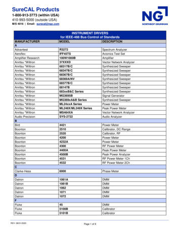
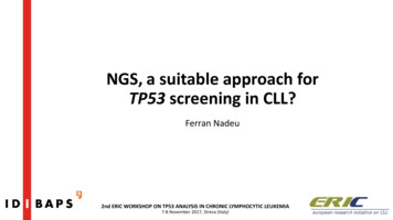
1Getting StartedThe Front Panel at a U1732BFigure 1-1 Front panel of U1731B and U1732B dual display handheld LCR meter4U1731B/U1732B User’s and Service Guide
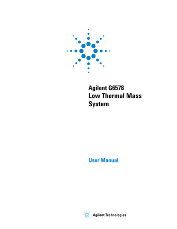
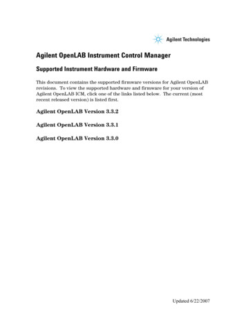
Getting Started1Display Annunciators8910 11 12 13 1415161718197652021222324254321Figure 1-2 LCD displayTable 1-1 Descriptions of each annunciatorNo.SymbolsDescriptions1Low battery indicator2Reading out of LO limit3Primary display4Reading out of HI limit5Auto power off indicator678TOL 1% 5% 10% 20%Tolerance mode, to set 1%, 5%, 10%, and 20% for sortingcapacitanceAUTOAUTO rangeCInductance, Capacitance, or Resistance (L,C, or R) functionindicatorU1731B/U1732B User’s and Service Guide5
1Getting StartedMAX AVG MINStatic recording modeMAX: Maximum reading9AVG: Average readingMIN: Minimum reading10RELRelative mode11DHData hold to hold the displayed digital value12qPhase angle indicator (only applicable for U1732B)13DDissipation factor indicator14QQuality factor indicator15Secondary display16Audible alert for tolerance and compare mode17%Unit for tolerance display (percentage)18degUnit for phase angle (degree) (only applicable for U1732B)19kHzUnit for beeper frequency as setup mode20PALParallel mode indicator21SERSeries mode indicator22mkWUnit for resistance (kΩ and MΩ)23Unit for inductance (µH and mH)24Unit for capacitance (pF, nF, µF, and mF)25Remote controlSpecial indication characters6DescriptionsDescriptionsIndicates short connectorsIndicates calibration modeIndicates open connectorsIndicates damaged or openfuseU1731B/U1732B User’s and Service Guide
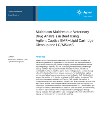
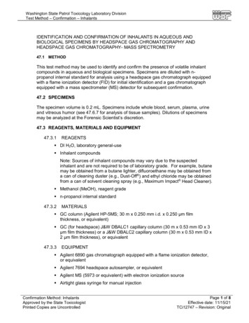
Getting Started1The Keypad at a Glance918273645Figure 1-3 Keypad of U1731B/U1732B dual display handheld LCR meterTable 1-2 Keypad descriptions and functionsNo. Keys1FunctionsPowerTo turn ON/OFF the instrument2D/Q/θTo select dissipation factor, quality factor, and phase angle display(only applicable for U1732B)3L/C/RP STo select inductance, capacitance, and resistance measurement4TOLTolerance mode5FREQTo select test frequencyRELRelative modeCALCalibration modeManualManual rangeAUTOAuto rangeHOLDData holdRECStatic recording modeREMOTETo toggle ON/OFF the remote function6789To toggle parallel and series modeBacklight display (only applicable for U1732B)U1731B/U1732B User’s and Service Guide7
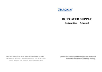
1Getting StartedThe Input Terminal at a GlanceTo avoid damaging this instrument, do not exceed the input limit. Do not applyvoltage to input terminals. Discharge the capacitor before testing.WA R N I N G213Figure 1-4 Input terminals/sockets of U1731B/U1732B dual display handheld LCR meterNo. Terminals Functions81 Positive terminal/socket2–Negative terminal/socket3GUARDGuard terminal/socketU1731B/U1732B User’s and Service Guide
U1731B/U1732B Dual Display Handheld LCR MeterUser’s and Service Guide2Features and FunctionsInductance Measurement 10Resistance Measurement 12Data Hold 13Static Recording 13Dissipation Factor/Quality Factor/Phase Angle 13Test Frequency 14LCR Function Selector 14Relative 14Tolerance 15Auto/Manual Range 15Automatic Fuse Detection 16Parallel/Series Mode 16CAL Function 17Enable/Disable Auto Power-Off 19Low Battery Indication 19Backlit Display (Only Available for U1732B) 19Communication (Optional Accessories) 20This chapters provides detailed information on the features and functionsthat are available in the U1731B/U1732B dual display handheld LCRmeter.Agilent Technologies9
2Features and FunctionsInductance MeasurementFigure 2-1 Inductance measurement1 Press thekey to power- on the LCR meter.2 Press the L/C/R key to select inductance (L) measurement.3 Insert an inductor into component receptacle socket or connect the testclip to the component leads as required.4 Press the FREQ key to select testing frequency.5 Press the D/Q or D/Q/q key to select Q factor for secondary display.6 Read the display readings for inductance value and quality factor.NOTE10It is recommended that you calibrate the LCR meter before testing to achieve optimumprecision for all L, C, and R measurements at either the highest or lowest ranges.U1731B/U1732B User’s and Service Guide
Features and Functions 2WA R N I N GTo avoid electrical hazards, discharge the capacitor to be tested before measuring.Capacitance MeasurementFigure 2-2 Capacitance measurement1 Press thekey to turn on the LCR meter.2 Press the L/C/R key to select capacitance (C) measurement.3 Insert a capacitor into the component receptacle socket or connect thetest clip to the component leads as required.4 Press the FREQ key to select testing frequency.5 Press the D/Q or D/Q/q key to select D factor for secondary display.6 Read the display readings for capacitance value and dissipation factor.U1731B/U1732B User’s and Service Guide11
2Features and FunctionsResistance MeasurementFigure 2-3 Resistance measurement1 Press thekey to turn on the LCR meter.2 Press the L/C/R key to select Resistance measurement.3 Insert a resistor into the component receptacle socket or connect thetest clip to the component leads as required.4 Press the FREQ key to select testing frequency.5 Read the display readings for resistance value.12U1731B/U1732B User’s and Service Guide
Features and Functions 2Data HoldThe data- hold function allows the user to freeze the display. To enter thismode, press the HOLD key. Press the key again to release.Static RecordingPress the REC key for more than one second to enter the static recordingmode. The maximum and minimum readings are then stored in memory.The beeper will beep once when a new reading has been recorded. Pressthe same key to cycle through the maximum, minimum, and average of thepresent readings.The MAX, MIN, or AVG annunciator will appear on the display to indicatewhich value is being displayed. Whenever the MAX AVG MIN anunciatorsappear on the display simultaneously, the display reading is always apresent value.To exit this mode, press and hold the key for more than one second.NOTE1 Static recording captures only stable values and updates the memory; it will not record anyoverload (OL) value for any of the LCR functions. In addition, the LCR meter will not record valuesbelow 50 counts in capacitance measurement.2 Static recording is only available in manual ranging; however, activation while in auto-ranging willautomatically set the LCR meter to manual ranging and cause calibration prompts to be displayedin the recommended ranges.Dissipation Factor/Quality Factor/Phase AngleThe D/Q/ q values can be displayed interchangeably by pressing the D/Q/q key when the LCR meter is set to inductance or capacitance mode. Thissetting does not apply to resistance measurement. The phase angle mode(q) is only available for the U1732B.U1731B/U1732B User’s and Service Guide13
2Features and FunctionsTest FrequencyThe testing frequency is set to 1 kHz by default. Press the FREQ key toselect the desired test frequency.LCR Function SelectorPress the L/C/R key to select the L, C, or R function as desired.RelativePress the REL key to enter the relative mode and store the displayreading as a reference value. It will then display all subsequent readingsrelative to reference value. Press the key again to exit the relative mode.NOTE141 The relative mode cannot be activated if the display value is either "OL" or "0000".2 Relative mode is only available in manual ranging; however, activation while in auto-ranging willautomatically set the LCR meter to manual ranging and cause calibration prompts to be displayedin the recommended ranges.3 The relative mode cannot be activated if the LCR meter is set at auto-ranging with data holdactivated.U1731B/U1732B User’s and Service Guide
Features and Functions 2ToleranceThe tolerance ranges available are 1%, 5%, 10%, and 20%. To entertolerance mode, insert the appropriate component as a standard value intothe socket or connect the component to the test probes, then press theTOL key to set this value, as the standard reference tolerance. Similarly,any value which appears on the display, such as DH or MAX/MIN/AVG,can be used as a standard value to sort components. Press this key againto cycle through 1%, 5%, 10% and 20% tolerance as desire.This function is designed for convenient component sorting. The beeperwill beep three times whenever the component under test exceeds thesetting tolerance. Conversely, when the beeper beeps once, this indicatesthat the component is within the setting tolerance.NOTE1 The tolerance mode cannot be activated if "OL” or "0000" is shown on the display or when thetested capacitance value is below 10 counts.2 Tolerance mode is only available in manual ranging; however, activation while in auto-ranging willautomatically set the LCR meter to manual ranging and cause calibration prompts to be displayedin the recommended ranges.3 The tolerance mode cannot be activated if the LCR meter is set to auto-ranging with data holdmode activated.4 The 20% tolerance selection is only available for U1732B.Auto/Manual RangeThe LCR meter is set to auto- ranging mode by default when the meter ispowered- on. For specific measurement, press AUTO/MANUAL key toselect manual ranging. To return to the auto- ranging mode, press and holdthe AUTO/MANUAL key for more than one second.U1731B/U1732B User’s and Service Guide15
2Features and FunctionsAutomatic Fuse DetectionWhen the LCR meter detects that the protective fuse is open or damaged,the FUSE character (as shown in Figure 2- 4) will appear on the displayand the beeper will beep continuously. In this situation, none of thefunction keys can be operated and all other LCR meter functions will bediscontinued. Fuse replacement is required. To replace protective fuse,refer to Chapter 3, “Fuse Replacement”.Figure 2-4 Fuse detectionParallel/Series ModeThe LCR meter can display parallel (PAL) and series (SER) mode data forall ranges. For capacitance and resistance measurements, the LCR meter isset to parallel mode by default. Series mode is the default setting forinductance measurement. Press the L/C/R key for more than one secondto toggle PAL and SER mode.16U1731B/U1732B User’s and Service Guide
Features and Functions 2CAL FunctionThe CAL function is a correction function which enables the LCR meter'sinternal parameters and external connector residues to be offset(corrected) to achieve measurements with higher accuracy. The CALfunction is only available for extremely high or low L, C, and R ranges.It is highly recommended that you correct extremely high or low rangesfor L, C, and R before making precision measurements. Correction (CAL)prompts will be displayed automatically every time these ranges aremanually or functionally selected, (e.g. REL, TOL, REC, etc.) and thereforecorrection is recommended.Figure 2-5 Open calibration and short calibrationMeasurements performed in extremely high or low ranges that requirecorrections are predefined as “open cal” or “short cal”. Refer to the“Specified Note” column of any of the L, C, or R measurement fromChapter 4, “U1731B Electrical Specifications,” starting on page 26 orChapter 4, “U1732B Electrical Specifications,” starting on page 29 to findout which of these measurement ranges are indicated with “After opencal” or “After short cal”. These predefined ranges will require you toconnect the terminal connection as “open” or “short” to achieve theaccuracy in the table.U1731B/U1732B User’s and Service Guide17
2Features and FunctionsFollow the instructions below to perform the CAL function:1 Press and hold the CAL key for more than one second to enter CALmode.2 CAL prompts will be shown on the display.3 Press the MANUAL key to select the desired range for correction. Followthe prompts instruction on the upper right of the display of theselected range for the terminal connection. Leave the positive andnegative connector terminals open for open connector (OPn) connection,or short the connector terminals at short connector (Srt) connection.4 Press the CAL key to start the correction function. The OPn or Srtannunciator on the upper right of the display will disappear to indicatethe start of the correction process.To skip the correction process, press D/Q/θ.5 The CAL annunciator on the main display will disappear once thecorrection process is completed. The LCR meter will be restored to thenormal display and ready to perform measurement.NOTE181 Changing measurement frequencies is handled the same way as selecting a different hardwarerange, and the automatic calibration prompts will be displayed in the recommended ranges.2 Ensure that the same testing position is used after short calibration.U1731B/U1732B User’s and Service Guide
Features and Functions 2Enable/Disable Auto Power-OffWhen the LCR meter has not been used for five minutes since the lastoperation, the beeper will beep a long tone. Then the LCR meter willautomatically enter sleep mode and none of the anunciators will shown onthe display. To re- activate the LCR meter, press any key.When the LCR meter must be used for a longer period, the auto power- offfunction can be disabled. To disable auto power- off, press and hold theL/C/R key while turning LCR meter ON. Release the L/C/R key and pressany key again. Theannunciator will disappear. This will confirmthat the auto power- off function has been disabled.When a 12 VAC adaptor is used as an optional power source, the autopower- off function is automatically disabled.NOTEIt is recommended that the LCR meter should always be powered off when not in use.Low Battery IndicationWhen theannunciator is blinking on the display, this shows that thebattery voltage is below normal working voltage and is weakening. Replacethe battery with a new battery to maintain the precision of the LCRmeter. To replace the battery, refer to Chapter 3, “Battery Replacement”.Backlit Display (Only Available for U1732B)Press and the holdkey for more than one second to togglebacklit ON/OFF. This function is only available for the U1732B.U1731B/U1732B User’s and Service Guide19
2Features and FunctionsCommunication (Optional Accessories)The LCR meter can be adapted for communication capability. The optionalIR- USB package comes with a full optically- isolated cable and software.This function enables you to record data easily. To use this function, youwill need a U1173A IR- to- USB cable (purchased separately) and the datalogging software. You can download the data logging software from theAgilent web site at: http://www.agilent.com.find/hhTechlib. Refer to thefollowing procedure to set up the communication between your LCR meterand personal computer (PC).1 Connect one side of the cable to the meter with the Agilent logo facingup and connect the USB connector to the PC.2 Press the REMOTE key to enable this interface; theannunciator will be shown on the display.3 Run the Data Logger software to transfer the data to the PC for yourapplications.4 To remove the cable, press and pull the snap ends on each side of thecable that is connected to the meter.The side with the Agilentlogo must be facing upConnect to the PC’s USB portPress the snaps to removethe cableFigure 2-6 Cable connection for remote communication20U1731B/U1732B User’s and Service Guide
U1731B/U1732B Dual Display Handheld LCR MeterUser’s and Service Guide3Service and MaintenanceService 22Battery Replacement 22Fuse Replacement 24Replacement Parts 25Cleaning the LCR Meter 26Specification Validation 27This chapter describes the service and maintenance procedures for theU1731B/U1732B dual display handheld LCR meter. Repair or service thatare not covered in this manual should only be performed by qualifiedpersonnel.Agilent Technologies21
3Service and MaintenanceServiceWA R N I N GTo avoid electrical shock, do not perform any service unless you are qualified to do so.If the instrument fails to operate, check the battery and test leads.Replace the battery or test leads if necessary. If the instrument stillcannot function, check again the operating procedures described in thisinstruction manual. When servicing, use specified replacement parts only.The LCR meter must be completely turned off while replacing either thefuse or battery.Battery ReplacementWA R N I N GDo not discharge the battery by shorting the battery or reversing the battery polarity.CAUTIONTo avoid instruments being damage from battery leakage: Always remove dead batteries immediately. Always remove the battery and store it separately if the LCR meter is not going to beused for a long period.The LCR meter is powered by a single 9 V alkaline battery. Replace thebattery if the low battery sign () is displayed and flashing. Use thefollowing procedures to replace the battery.1 Loosen screws with a suitable screwdriver and remove the battery coveras shown in Figure 3- 1.2 Replace the degraded battery with a new battery.22U1731B/U1732B User’s and Service Guide
Service and Maintenance3Battery cover screwFigure 3-1 Battery replacementU1731B/U1732B User’s and Service Guide23
3Service and MaintenanceFuse ReplacementNOTEUsers should use clean/dry gloves when performing fuse replacement. Do not touch anycomponents except the fuse and plastic parts. No recalibration is required after replacingthe fuse.The LCR meter is able to self- detect if the input protective fuse is eitheropen or damaged. In this case, the display will show FUSE and beep willsound continuously, warning the user to replace the damaged fuse tomaintain the accuracy of measurement. While replacing the fuse, the LCRmeter must be completely turned off.1 Loosen screws with a suitable screwdriver and remove the battery coveras shown in Figure 3- 1.2 Loosen screws with a suitable screwdriver and remove the bottom coveras shown in Figure 3- 2.3 Replace the damaged fuse with the a new fuse as specified in
The 20,000-count dual display handheld LCR meters (U1731B and U1732B) are special microprocessor-controlled meters for inductance, capacitance, and resistance measurements. The LCR meter is simple to operate and is capable of making absolute parallel mode measurements as well as series mode measurement. The LCR meter provides direct and