Transcription
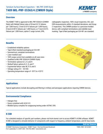
Tantalum Surface Mount Capacitors – MIL-PRF (CWR Style)T409 MIL-PRF-55365/4 (CWR09 Style)OverviewThe KEMET T409 is approved to MIL-PRF-55365/4 (CWR09Style) with Weibull failure rates of B level (0.1% failuresper 1,000 hours), C level (0.01% failures per 1,000 hours),D level (0.001% failures per 1,000 hours), or T level (0.01%failures per 1,000 hours, option C surge current, DPA,radiographic inspection, 100% visual inspection, DCL andESR measurements within 3 standard deviations, and GroupC inspection). This CWR09 product is a precision-moldeddevice, with compliant terminations and indelible lasermarking. Tape & Reel packaging per EIA 481 are standard.Benefits Established reliability optionsTape & Reel standard packaging per EIA 481Symmetrical, compliant terminationsLaser-marked case100% surge current test available on all case sizesQualified to MIL-PRF-55365/4 (CWR09 Style)Termination options B, C, H, and KWeibull failure options B, C, D, and TExponential failure rates M, P, R, and SVoltage rating of 4 – 50 VDCOperating temperature range of 55 C to 125 CApplicationsTypical applications include decoupling and filtering in military and aerospace applications requiring CWR09 devices.Environmental Compliance Halogen-free Epoxy compliant with UL94 V-0 Molded Epoxy complies for outgassing testing under ASTM E 595.K-SIMFor a detailed analysis of specific part numbers, please visit ksim.kemet.com to access KEMET’s K-SIM software. KEMETK-SIM is designed to simulate behavior of components with respect to frequency, ambient temperature, and DC bias levels.Built Into Tomorrow KEMET Electronics Corporation KEMET Tower One East Broward Boulevard Fort Lauderdale, FL 33301 USA 954-766-2800 www.kemet.comT2001 T409 10/12/20211
Tantalum Surface Mount Capacitors – MIL-PRF (CWR Style)T409 MIL-PRF-55365/4 (CWR09 Style)KEMET Ordering InformationT409A225K004RatedCase Capacitance CapacitanceVoltageSizeCode (pF)Tolerance(VDC)T CWR 09AFirst twoJ 5%004 4Tantalum Established BdigitsK 10%006 6reliabilityCrepresentM 20% 010 10Dsignificant015 15Efigures.020 20F025 25Third digitGspecifies035 35H050 50number ofzeros.CapacitorClassSeriesAH42527280Failure WeibullA Non-ERB (0.1%/1,000 hours)C (0.01%/1,000 hours)D (0.001%/1,000hours)T (0.01%/1,000 hours)ExponentialM (1.0%/1,000 hours)P (0.1%/1,000 hours)R (0.01%/1,000 hours)S (0.001%/1,000 hours)C Hot solderdippedH Standardsolder-coated(SnPb 5% Pbminimum)B Gold-platedK Solderfused4250 25 Cafter Weibull4251 55 Cand 85 C afterWeibull4252 55 Cand 85 Cbefore WeibullTLVL Weibullgrade level "T"Blank 7" Reel7280 13" Reel7610 Bulk bag7640 Bulkplastic boxWAFL WafflepackOrdering Information – Defense MIL-PRF-55365/4CWR09JH105KCACapacitor Code(pF)CapacitanceToleranceReliability LevelSurge Current OptionPerMIL-PRF-55365/4C 4D 6F 10H 15J 20K 25M 35N 50B Gold-plated First two digits J 5%C Hot solderrepresentK 10%dippedsignificantM 20%figures. ThirdH Solderdigit specifiesplatednumber ofK Solderzeros.fusedWeibullA non-ERB (0.1%/1,000 hours)C (0.01%/1,000 hours)D (0.001%/1,000 hours)T T Level* (0.01%/1,000 hours)ExponentialM (1.0%/1,000 hours)P (0.1%/1,000 hours)R (0.01%/1,000 hours)S (0.001%/1,000 hours)A 25 C after WeibullB 55 C 85 C after WeibullC 55 C 85 C before WeibullBlank No surge* When T Level is ordered, no Surge Current Option is neededPerformance CharacteristicsItemPerformance CharacteristicsOperating TemperatureRated Capacitance RangeCapacitance ToleranceRated Voltage Range 55 C to 125 C0.1 – 100 µF at 120 Hz/25 CJ Tolerance (5%), K Tolerance (10%), M Tolerance (20%)4 – 50 VDF (120 Hz)Refer to Part Number Electrical Specification TableESR (100 kHz)Refer to Part Number Electrical Specification TableLeakage Current 0.01 CV (µA) at rated voltage after 5 minutes KEMET Electronics Corporation KEMET Tower One East Broward Boulevard Fort Lauderdale, FL 33301 USA 954-766-2800 www.kemet.comT2001 T409 10/12/20212
Tantalum Surface Mount Capacitors – MIL-PRF (CWR Style)T409 MIL-PRF-55365/4 (CWR09 Style)QualificationTestConditionCharacteristicsΔ C/CEndurance85 C at rated voltage, 2,000 hours125 C at 2/3 rated voltage, 2,000 hoursWithin initial limitsDCLWithin 1.25 x initial limitESRWithin initial limitsΔ C/CStorage Life125 C at 0 volts, 2,000 hoursTemperature StabilityMIL-STD-202, Method 107, condition B, mounted, 55C to 125 C, 1,000 cyclesExtreme temperature exposure at asuccession of continuous steps at 25 C, 55 C, 25 C, 85 C, 125 C, 25 CWithin initial limitsDCLWithin 1.25 x initial limitESRWithin initial limitsMechanical Shock/VibrationAdditional qualificationtests per MIL-PRF-55365/4Within 5% of initial valueDFWithin initial limitsDCLWithin 1.25 x initial limitESRWithin initial limits 25 C 55 C 85 C 125 CΔ C/CIL* 10% 10% 15%DFILIL1.5 x IL1.5 x ILDCLILN/A10 x IL12 x ILΔ C/CSurge VoltageWithin 10% of initial valueDFΔ C/CThermal ShockWithin 10% of initial valueDF25 C and 85 C, 1.32 x rated voltage 1,000 cycles(125 C, 1.2 x rated voltage)MIL-STD-202, Method 213, Condition I, 100 G peakMIL-STD-202, Method 204, Condition D,10 Hz to 2,000 Hz, 20 G peakWithin 5% of initial valueDFWithin initial limitsDCLWithin initial limitsESRWithin initial limitsΔ C/CWithin 10% of initial valueDFWithin initial limitsDCLWithin initial limitsPlease contact KEMET for more information.*IL Initial limitCertificationMIL-PRF-55365/4 KEMET Electronics Corporation KEMET Tower One East Broward Boulevard Fort Lauderdale, FL 33301 USA 954-766-2800 www.kemet.comT2001 T409 10/12/20213
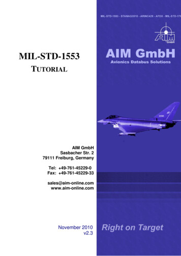
Tantalum Surface Mount Capacitors – MIL-PRF (CWR Style)T409 MIL-PRF-55365/4 (CWR09 Style)Electrical CharacteristicsCapacitance vs. FrequencyESR vs. Frequency1001,000T409F156/010T409F156/010 IMPT409H476/010 IMPT409D475/010 ESRT409F156/010 ESRT409F476/010 ESR10Capacitance (µF)Impedance, ESR (Ohms)T409D475/010T409D475/010 uency (Hz)1,000,00010,000,000 KEMET Electronics Corporation KEMET Tower One East Broward Boulevard Fort Lauderdale, FL 33301 USA 954-766-2800 www.kemet.com0.11001,00010,000100,000Frequency (Hz)1,000,00010,000,000T2001 T409 10/12/20214
Tantalum Surface Mount Capacitors – MIL-PRF (CWR Style)T409 MIL-PRF-55365/4 (CWR09 Style)Dimensions – Millimeters (Inches)Metric will governSIDE VIEWEND VIEWLHPWTermination cutoutat KEMET's option,either endH2BOTTOM VIEWSolderableSurfaces½ H2 Min.W2PCase SizeComponentW 0.38 (0.015) H 0.38 (0.015)P 0.25 (0.010), 0.13 (0.005)KEMETL 0.38 (0.015)A2.54 (0.100)1.27 (0.050)1.27 (0.050)0.76 (0.030)B3.81 (0.150)1.27 (0.050)1.27 (0.050)0.76 (0.030)C5.08 (0.200)1.27 (0.050)1.27 (0.050)0.76 (0.030)D3.81 (0.150)2.54 (0.100)1.27 (0.050)0.76 (0.030)E5.08 (0.200)2.54 (0.100)1.27 (0.050)0.76 (0.030)F5.59 (0.220)3.43 (0.135)1.78 (0.070)0.76 (0.030)G6.73 (0.265)2.79 (0.110)2.79 (0.110)1.27 (0.050)H7.24 (0.285)3.81 (0.150)2.79 (0.110)1.27 (0.050)Typical WeightW21.27 0.13(0.050 0.005)1.27 0.13(0.050 0.005)1.27 0.13(0.050 0.005)2.41 0.13, 0.25(0.095 0.005, 0.010)2.41 0.13, 0.25(0.095 0.005, 0.010)3.30 0.13(0.130 0.005)2.67 0.13(0.105 0.005)3.68 0.013, 0.51(0.145 0.005, 0.020)H2 Minimum(mg)0.76 (0.030)39.910.76 (0.030)68.730.76 (0.030)146.50.76 (0.030)264.120.76 (0.030)421.631.02 (0.040)173.631.52 (0.060)266.421.52 (0.060)349.01Note: When option C is selected for lead material, add an additional 0.38 mm (0.015 inch) to the above tolerances for "L", "W", "H", "P", "W2," and "H2."These weights are provided as reference. If exact weights are needed, please contact your KEMET sales representative. KEMET Electronics Corporation KEMET Tower One East Broward Boulevard Fort Lauderdale, FL 33301 USA 954-766-2800 www.kemet.comT2001 T409 10/12/20215
Tantalum Surface Mount Capacitors – MIL-PRF (CWR Style)T409 MIL-PRF-55365/4 (CWR09 Style)Table 1 – Ratings & Part Number ReferenceRated RatedVoltage CapCaseCode/Case SizeKEMET PartNumberMIL-PRF-55365/4DCPart NumberLeakageµA at 25 1.0VDC @ 85 CµFKEMET/EIA(See below forpart options)(See below forpart 2)(5)VDC @ 85 CµFKEMET/EIA(See below forpart options)(See below forpart options)µA at 25 CMaximum/5MinutesRatedVoltageRatedCapCase Code/Case SizeKEMET Part NumberMIL-PRF-55365/4Part NumberDCLeakageDFESR% at 25 C120 6.0% at 25 C120 HzMaximumΩ at 25 C100 53.5Ω at 25 C100 kHzMaximumDFESRMaximumOperatingTempMSL CReflow Temp 260 11111111111111111111111111111111111 CReflow Temp 260 CMaximumOperating TempMSL(1) To complete KEMET/CWR part number, insert M for 20%, K for 10%, or J for 5%. Designates Capacitance Tolerance.(2) To complete KEMET/CWR part number, insert failure rate letter per the Ordering Information found on page 2. Designates Reliability Level.(3) To complete KEMET/CWR part number, insert B Gold-plated, C Hot solder dipped, H Solder-plated or K Solder fused. Designates terminationfinish.(4) To complete KEMET part number, insert 4250 25 C after Weibull, 4251 55 C 85 C after Weibull, or 4252 55 C 85 C before Weibull.Designates Surge Current Option.(5) To complete CWR part number, insert A 25 C after Weibull, B 55 C 85 C after Weibull, or C 55 C 85 C before Weibull. Designates surgecurrent option. Refer to Ordering Information for additional detail. KEMET Electronics Corporation KEMET Tower One East Broward Boulevard Fort Lauderdale, FL 33301 USA 954-766-2800 www.kemet.comT2001 T409 10/12/20216
Tantalum Surface Mount Capacitors – MIL-PRF (CWR Style)T409 MIL-PRF-55365/4 (CWR09 Style)Table 1 – Ratings & Part Number Reference cont.Rated RatedVoltage CapCaseCode/Case SizeKEMET PartNumberMIL-PRF-55365/4DCPart NumberLeakageVDC @ 85 CµFKEMET/EIA(See below forpart options)(See below forpart )(5)CWR09N(3)475(1)(2)(5)VDC @ 85 CµFKEMET/EIA(See below forpart options)(See below forpart options)RatedVoltageRatedCapCase Code/Case SizeKEMET Part NumberMIL-PRF-55365/4Part NumberMaximumOperatingTempMSLDFESRµA at 25 3.01.01.01.01.01.01.01.01.02.02.03.0µA at 25 CMaximum/5Minutes% at 25 C120 06.06.06.06.06.06.06.06.06.0% at 25 C120 HzMaximumΩ at 25 C100 .017.014.012.08.07.06.04.02.52.01.5Ω at 25 C100 kHzMaximum CReflow Temp 260 2512512512512512512511111111111111111111111 CReflow Temp 260 CDCLeakageDFESRMaximumOperating TempMSL(1) To complete KEMET/CWR part number, insert M for 20%, K for 10%, or J for 5%. Designates Capacitance Tolerance.(2) To complete KEMET/CWR part number, insert failure rate letter per the Ordering Information found on page 2. Designates Reliability Level.(3) To complete KEMET/CWR part number, insert B Gold-plated, C Hot solder dipped, H Solder-plated or K Solder fused. Designates terminationfinish.(4) To complete KEMET part number, insert 4250 25 C after Weibull, 4251 55 C 85 C after Weibull, or 4252 55 C 85 C before Weibull.Designates Surge Current Option.(5) To complete CWR part number, insert A 25 C after Weibull, B 55 C 85 C after Weibull, or C 55 C 85 C before Weibull. Designates surgecurrent option. Refer to Ordering Information for additional detail. KEMET Electronics Corporation KEMET Tower One East Broward Boulevard Fort Lauderdale, FL 33301 USA 954-766-2800 www.kemet.comT2001 T409 10/12/20217
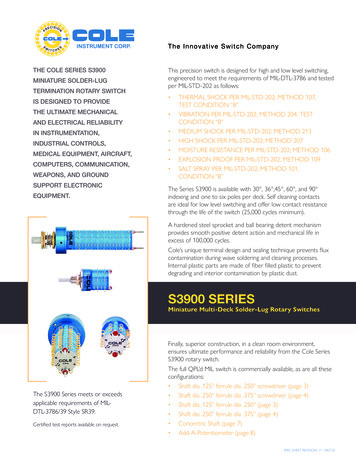
Tantalum Surface Mount Capacitors – MIL-PRF (CWR Style)T409 MIL-PRF-55365/4 (CWR09 Style)Recommended Voltage Derating Guidelines85 C to 125 CVR67% of VR50% of VR33% of VR120%100%% Working Voltage% Change in Working DCVoltage with TemperatureRecommended MaximumApplication Voltage 55 C to 85 C80%% Change in Working DC Voltagewith Temperature67%60%40%20%0% 55Recommended MaximumApplication Voltage(As % of Rated Voltage)2533%85Temperature (ºC)125Ripple Current/Ripple VoltagePermissible AC ripple voltage and current are related toMaximum PowerKEMETEIADissipation (P max)equivalent series resistance (ESR) and the power dissipationCase CodeCase CodemWatts at 25 Ccapabilities of the device. Permissible AC ripple voltagew/ 20 C Risewhich may be applied is limited by two criteria:A2513501. The positive peak AC voltage plus the DC bias voltage,B381370if any, must not exceed the DC voltage rating of theC511375capacitor.D3825802. The negative peak AC voltage in combination withE512590bias voltage, if any, must not exceed the allowable limitsF5634100specified for the reverse voltage. See the Reverse VoltageG6728125section for allowable limits.H7238150The maximum power dissipation by case size can beX6954165determined using the table at right. The maximum powerdissipation rating stated in the table must be reduced withUsing the P max of the device, the maximum allowable rmsincreasing environmental operating temperatures. Refer toripple current or voltage may be determined.the table below for temperature compensation requirements.Temperature Compensation Multipliersfor Maximum Ripple CurrentT 25 C1.00T 85 C0.90T 125 C0.40T Environmental TemperatureI(max) P max/RE(max) Z P max/RI rms ripple current (amperes)E rms ripple voltage (volts)P max maximum power dissipation (watts)R ESR at specified frequency (ohms)Z Impedance at specified frequency (ohms)The maximum power dissipation rating must be reduced with increasingenvironmental operating temperatures. Refer to the TemperatureCompensation Multiplier table for details. KEMET Electronics Corporation KEMET Tower One East Broward Boulevard Fort Lauderdale, FL 33301 USA 954-766-2800 www.kemet.comT2001 T409 10/12/20218
Tantalum Surface Mount Capacitors – MIL-PRF (CWR Style)T409 MIL-PRF-55365/4 (CWR09 Style)Reverse VoltageSolid tantalum capacitors are polar devices and may be permanently damaged or destroyed if connected with the wrongpolarity. The positive terminal is identified on the capacitor body by a stripe, plus, in some cases a beveled edge. A smalldegree of transient reverse voltage is permissible for short periods per the table. The capacitors should not be operatedcontinuously in reverse mode, even within these limits.TemperaturePermissible Transient Reverse Voltage25 C85 C125 C15% of Rated Voltage5% of Rated Voltage1% of Rated VoltageTable 2 – Land Dimensions/CourtyardKEMETMetricSizeCodeDensity Level A:Maximum (Most) LandProtrusion (mm)Density Level B:Median (Nominal) LandProtrusion (mm)Density Level C:Minimum (Least) LandProtrusion .164.063.424.446.04Density Level A: For low-density product applications. Recommended for wave solder applications and provides a wider process window for reflowsolder processes.Density Level B: For products with a moderate level of component density. Provides a robust solder attachment condition for reflow solder processes.Density Level C: For high component desity product applications. Before adapting the minimum land pattern variations, the user should performqualification testing based on the conditions outlined in IPC standard 7351 (IPC–7351).1Land pattern geometry is too small for silkscreen outline.V1LLWWV2SGrid Placement Courtyard KEMET Electronics Corporation KEMET Tower One East Broward Boulevard Fort Lauderdale, FL 33301 USA 954-766-2800 www.kemet.comT2001 T409 10/12/20219
Tantalum Surface Mount Capacitors – MIL-PRF (CWR Style)T409 MIL-PRF-55365/4 (CWR09 Style)Soldering ProcessKEMET’s families of surface mount capacitors are compatiblewith wave (single or dual), convection, IR, or vapor phasereflow techniques. Preheating of these components isrecommended to avoid extreme thermal stress. KEMET'srecommended profile conditions for convection and IRreflow reflect the profile conditions of the IPC/J–STD–020Dstandard for moisture sensitivity testing. The devices cansafely withstand a maximum of three reflow passes at theseconditions.Please note that although the X/7343–43 case size canwithstand wave soldering, the tall profile (4.3 mm maximum)dictates care in wave process development.Profile FeatureSnPb Assembly Pb-Free AssemblyPreheat/SoakTemperature Minimum (TSmin)100 C150 CTemperature Maximum (TSmax)150 C200 CTime (ts) from Tsmin to Tsmax)60 – 120 seconds60 – 120 secondsRamp-up Rate (TL to TP)3 C/second maximum3 C/second maximumLiquidous Temperature (TL)183 C217 CTime Above Liquidous (tL)60 – 150 seconds220 C*235 C**60 – 150 seconds250 C*260 C**20 seconds maximum30 seconds maximum6 C/second maximum6 C/second maximum6 minutes maximum8 minutes maximumPeak Temperature (TP)Time within 5 C of MaximumPeak Temperature (tP)Ramp-down Rate (TP to TL)Time 25 C to PeakTemperatureNote: All temperatures refer to the center of the package, measured on theDuring typical reflow operations, a slight darkening of thegold-colored epoxy may be observed. This slight darkening isnormal and not harmful to the product. Marking permanencyis not affected by this change.TemperatureHand soldering should be performed with care due to thepackage body surface that is facing up during assembly reflow.difficulty in process control. If performed, care should be* For Case Size height 2.5 mm** For Case Size height 2.5 mmtaken to avoid contact of the soldering iron to the moldedcase. The iron should be used to heat the solder pad, applyingsolder between the pad and the termination, until reflowTPtPMaximum Ramp Up Rate 3 C/secondoccurs. Once reflow occurs, the iron should be removedMaximum Ramp Down Rate 6 C/secondTLimmediately. “Wiping” the edges of a chip and heating the toptLsurface is not recommended.TsmaxTsmin25ts25 C to PeakTimeStorageTantalum chip capacitors should be stored in normal working environments. While the chips themselves are quite robust inother environments, solderability will be degraded by exposure to high temperatures, high humidity, corrosive atmospheres,and long term storage. In addition, packaging materials will be degraded by high temperature – reels may soften or warpand tape peel force may increase. KEMET recommends that maximum storage temperature not exceed 40 C and maximumstorage humidity not exceed 60% relative humidity. Temperature fluctuations should be minimized to avoid condensation onthe parts and atmospheres should be free of chlorine and sulphur bearing compounds. For optimized solderability chip stockshould be used promptly, preferably within three years of receipt. KEMET Electronics Corporation KEMET Tower One East Broward Boulevard Fort Lauderdale, FL 33301 USA 954-766-2800 www.kemet.comT2001 T409 10/12/202110
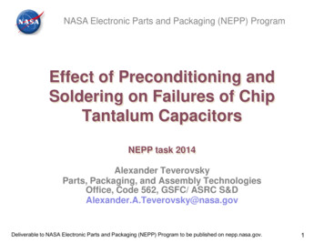
Tantalum Surface Mount Capacitors – MIL-PRF (CWR Style)T409 MIL-PRF-55365/4 (CWR09 Style)ConstructionMolded EpoxyCasePolarity Stripe ( )Detailed Cross SectionSilver Paint(Fourth Layer)Tantalum WireLeadframe( Cathode)WasherTantalum WireWeld(to attach wire)Carbon(Third Layer)Silver AdhesiveLeadframe( Anode)Molded EpoxyCaseMnO2(Second Layer)WasherTa2O5 Dielectric(First Layer)TantalumCapacitor MarkingPolarityIndicator ( )KEMET CWR09 StyleDate Code *1 digit last number of year7 20178 20189 20190 20201 20212 20222nd and 3rd digit week of theyear01 1st week of the year to52 52nd week of the yearstPicofaradCodeKEMETIDRatedVoltageDateCode** 116 16th week of 2021 KEMET Electronics Corporation KEMET Tower One East Broward Boulevard Fort Lauderdale, FL 33301 USA 954-766-2800 www.kemet.comT2001 T409 10/12/202111
Tantalum Surface Mount Capacitors – MIL-PRF (CWR Style)T409 MIL-PRF-55365/4 (CWR09 Style)Tape & Reel Packaging InformationKEMET’s molded tantalum and aluminum chip capacitor families are packaged in 8 and 12 mm plastic tape on 7" and 13"reels in accordance with EIA Standard 481: Embossed Carrier Taping of Surface Mount Components for Automatic Handling.This packaging system is compatible with all tape-fed automatic pick-and-place systems.Right handorientationonly( )Embossed carrier( )EmbossmentTop tape thickness0.10 mm (0.004”)maximum thickness180 mm (7.0”) or330 mm (13.”)8 mm (0.315”) or12 mm (0.472”)Table 3 – Packaging QuantityKEMET 2824TapeWidth(mm)81212121212121212Tape and Reel Dimensions180 mm330 mm(7" diameter) (13" 09,5009,5009,5009,5003,5002,5002,5002,500 KEMET Electronics Corporation KEMET Tower One East Broward Boulevard Fort Lauderdale, FL 33301 USA 954-766-2800 www.kemet.comT2001 T409 10/12/202112
Tantalum Surface Mount Capacitors – MIL-PRF (CWR Style)T409 MIL-PRF-55365/4 (CWR09 Style)Figure 1 – Embossed (Plastic) Carrier Tape DimensionsP2TT2ØD0P0(10 pitches cumulativetolerance on tape 0.2 mm)A0E1FK0B1E2B0S1WP1T1Center Lines of CavityB1 is for tape feeder reference only,including draft concentric about B0.EmbossmentFor cavity size,see Note 1, Table 4ØD1Cover TapeUser Direction of UnreelingTable 4 – Embossed (Plastic) Carrier Tape DimensionsMetric will governConstant Dimensions — Millimeters (Inches)Tape Size8 mm12 mmD1 MinimumNote 1D01.5 0.10/ 0.0(0.059 0.004/ 0.0)1.0(0.039)1.5(0.059)E1P0R Reference S1 MinimumT1T MaximumNote 2Note 3MaximumP21.75 0.104.0 0.102.0 0.05(0.069 0.004) (0.157 0.004) (0.079 0.100(0.004)Variable Dimensions — Millimeters (Inches)Tape SizePitchB1 MaximumNote 48 mmSingle (4 mm)4.35(0.171)6.25(0.246)12 mmSingle (4 mm)and Double(8 mm)8.2(0.323)10.25(0.404)E2 MinimumFP13.5 0.052.0 0.05 or 4.0 0.10(0.138 0.002) (0.079 0.002 or 0.157 0.004)2.0 0.05 (0.079 0.002) or5.5 0.054.0 0.10 (0.157 0.004) or 8.0(0.217 0.002) 0.10 (0.315 0.004)T2 Maximum W Maximum A0, B0 & K02.5(0.098)8.3(0.327)4.6(0.181)12.3(0.484)Note 51. The embossment hole location shall be measured from the sprocket hole controlling the location of the embossment. Dimensions of embossmentlocation and hole location shall be applied independent of each other.2. The tape, with or without components, shall pass around R without damage (see Figure 4).3. If S1 1.0 mm, there may not be enough area for cover tape to be properly applied (see EIA Standard 481–D, paragraph 4.3, section b).4. B1 dimension is a reference dimension for tape feeder clearance only.5. The cavity defined by A0, B0 and K0 shall surround the component with sufficient clearance that:(a) the component does not protrude above the top surface of the carrier tape.(b) the component can be removed from the cavity in a vertical direction without mechanical restriction, after the top cover tape has been removed.(c) rotation of the component is limited to 20 maximum for 8 and 12 mm tapes (see Figure 2).(d) lateral movement of the component is restricted to 0.5 mm maximum for 8 mm and 12 mm wide tape (see Figure 3).(e) see Addendum in EIA Standard 481–D for standards relating to more precise taping requirements. KEMET Electronics Corporation KEMET Tower One East Broward Boulevard Fort Lauderdale, FL 33301 USA 954-766-2800 www.kemet.comT2001 T409 10/12/202113
Tantalum Surface Mount Capacitors – MIL-PRF (CWR Style)T409 MIL-PRF-55365/4 (CWR09 Style)Packaging Information Performance Notes1. Cover Tape Break Force: 1.0 kg minimum.2. Cover Tape Peel Strength: The total peel strength of the cover tape from the carrier tape shall be:Tape WidthPeel Strength8 mm0.1 to 1.0 Newton (10 to 100 gf)12 and 16 mm0.1 to 1.3 Newton (10 to 130 gf)The direction of the pull shall be opposite the direction of the carrier tape travel. The pull angle of the carrier tape shall be165 to 180 from the plane of the carrier tape. During peeling, the carrier and/or cover tape shall be pulled at a velocity of300 10 mm/minute.3. Labeling: Bar code labeling (standard or custom) shall be on the side of the reel opposite the sprocket holes. Refer to EIAStandards 556 and 624.Figure 2 – Maximum Component Rotation TMaximum Component RotationTop ViewMaximum Component RotationSide ViewTypical Pocket CenterlineTapeWidth (mm)8, 12BoMaximumRotation (20 T) sTapeMaximumWidth (mm) Rotation (8, 1220Typical Component Centerline S)AoFigure 3 – Maximum Lateral MovementFigure 4 – Bending Radius8 mm & 12 mm Tape0.5 mm maximum0.5 mm maximumEmbossedCarrierPunchedCarrierR KEMET Electronics Corporation KEMET Tower One East Broward Boulevard Fort Lauderdale, FL 33301 USA 954-766-2800 www.kemet.comBendingRadiusRT2001 T409 10/12/202114
Tantalum Surface Mount Capacitors – MIL-PRF (CWR Style)T409 MIL-PRF-55365/4 (CWR09 Style)Figure 5 – Reel DimensionsFull Radius,See NoteW3(Includesflange distortionat outer edge)Access Hole atSlot Location(Ø 40 mm minimum)W2DA(See Note)NC(Arbor holediameter)B(see Note)(Measured at hub)W1(Measured at hub)If present,tape slot in corefor tape start:2.5 mm minimum width x10.0 mm minimum depthNote: Drive spokes optional; if used, dimensions B and D shall apply.Table 5 – Reel DimensionsMetric will governConstant Dimensions — Millimeters
Laser-marked case 100% surge current test available on all case sizes Qualified to MIL-PRF-55365/4 (CWR09 Style) Termination options B, C, H, and K Weibull failure options B, C, D, and T Exponential failure rates M, P, R, and S Voltage rating of 4 - 50 VDC Operating temperature range of 55 C to 125 C Overview