Transcription
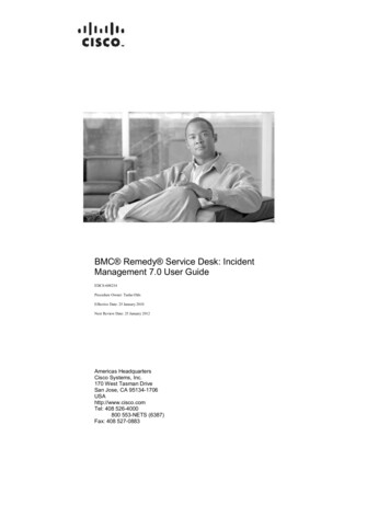
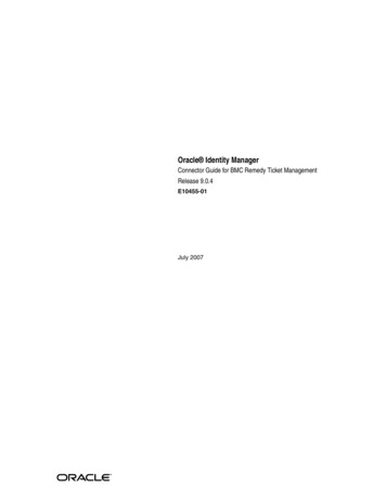
Asia-Pacific Conference on FRP in Structures (APFIS 2007)S.T. Smith (ed) 2007 International Institute for FRP in ConstructionFRP APPLICATION TO REMEDY AS-BUILT CONSTRUCTION DEFECTSD. Choudhuri, A. Bouadi and E. GreenWalter P Moore3131 Eastside Second FloorHouston, Texas 77098ABSTRACTThis paper will address the use of FRP to remedy construction defects in fast track construction projects inNorth America. One case study will be presented to expound on the application of the use of CFRP whenintrinsic defects are built in construction projects. The development and use of non-destructive testing toassess the problem, the protocol for witness testing for the FRP retrofit application and the post installed FRPQA/QC testing will be presented. Discussion of durability and fireproofing concerns from the owner’s sidefor such projects will be included in this paper.KEYWORDSFRP, Shear, Contact Critical, Bond Critical, Splice, Construction Defects, Strengthening.INTRODUCTION“Fast Track Construction” is not a contractual arrangement, but an approach used to allow for the earliestcompletion time possible by overlapping the design and construction phases. Under this approach, theGeneral Contractor is usually working for the Owner under a guaranteed maximum or design/build contract.This method attempts to reduce the total design and construction schedule because the contractor is securingfirm pricing, ordering long-lead delivery items, and starting construction as design phases are completed bythe architect/engineer, The General Contractor can begin work on this phase immediately as opposed towaiting for the whole project to be designed and bid. However, the sheer speed of construction on suchprojects can result in field changes being made by the erector without fully understanding the actual impactof those changes and also as-built construction defects.The case study presented in this paper relating to use of FRP to remedy construction defects in a fast trackstadium expansion project. A college football stadium was undergoing a 75 million dollar expansionproject to increase the capacity of the stadium to 55,000 spectators and columns on the gridline G of the mainconcourse exhibited cracking during construction. An evaluation was conducted understand the reason/s forthe distress and subsequently an FRP strengthening scheme was implemented quickly with limited impact onconstruction schedule.CASE STUDY 1 – FOOTBALL STADIUM EXPANSIONPROJECT DESCRIPTIONThe college stadium expansion project’s focal point was a north end zone expansion where seating was addedat two levels above the main concourse. The additions consisted of about 15000 upper concourse seats, 10luxury boxes, 7000 square feet player’s locker room, 3000 square feet player’s lounge, office for the coachesand other areas for the press. The new upper concourse framing was structural steel supported on reinforcedconcrete columns.541
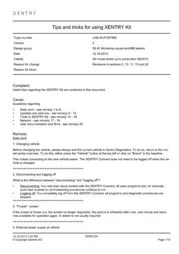
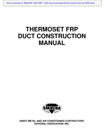
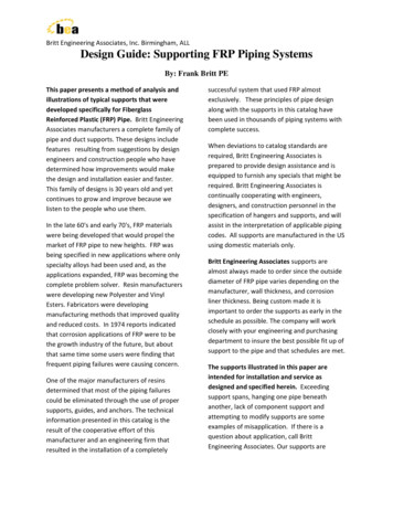
Figure 1. Architectural Rendering of the Proposed ExpansionTHE PROBLEMIn order to support the upper concourse the reinforced concrete columns on gridline G (G202 through G 209)were designed with an embed plate on the north face of the columns (see Figure 2). These columns,typically 30” inch x 42”, inch were designed with embed plates and gusset plates that would connect to strutelements to carry loads from the suite level, the upper concourse level and additional upper level bleachers.Figure 2 shows a schematic cross-section of the north end zone. The design called for gusset plates to beshop welded to the embed plates prior to being attached to the column. The embed plates were designed toextend for the full width of the north face (30 inch) of the columns on gridline G for a height of 6-1/2 feetand was 1-1/2 inch thick. The embed plates were attached to the concrete columns with 13 rows (6 rowswide) of ¾” inch diameter x 8” inch long headed studs (total of 78 studs for the 30 inch wide columns). Thecolumns were designed with 26 #11 bars with #4 ties at 3” inch on center in the embed plate zone. The clearcover to the ties was specified as 1-1/2 inch. Figure 3 shows a schematic of a typical column on gridline G.Figure 2. Schematic showing the proposed upper concourse supported of the reinforced concrete columnsfrom the main concourse levelDuring the construction of the columns on gridline G at the main concourse level the embed plates werefabricated and placed without the gusset plates. After these columns were poured the gusset plates weresubsequently field welded on the associated embed plates. As mentioned above the original designdocuments called for shop welds between the gusset plates and embed plates. Cracking distress was notedAPFIS 2007542
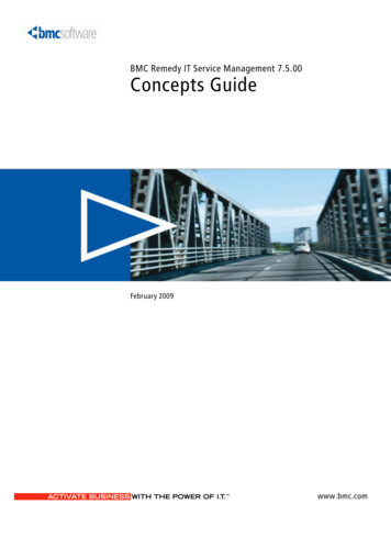
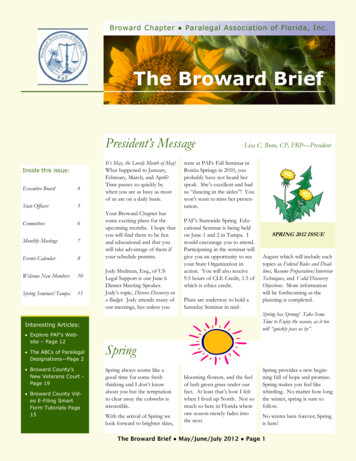
subsequent to the field welding operations. At the time the cracking distress was noted on the columns ongridline G; the gravity loading was approximately 40% of the final anticipated dead loads.Figure 3. Schematic of a typical column on gridline G.Our field evaluation consisted of visual assessment, non-destructive testing and destructive testing. Based onour assessment we were able to determine the following: Cracks on the columns were primarily on the east and west faces of the columns and the widthsvaried between hairline cracks to 1/4 inch. These cracks typically ran the lengths of the embedplates and in some instances extended beyond it (Figures 4 and 5).Typically there was a 1/8 inch gap between the embed plate and concrete on the north face of thecolumn.Ground Penetrating Radar (GPR) evaluation of the columns indicated variability of concrete coverbetween 2 inch – 6 inch from the column faces.Impact Echo data suggested that these cracks were deep and hence needed to be repaired.Ground Penetrating Radar (GPR) evaluation also suggested the tie spacing in the embed zone wasexcessive in the embed zone.Limited exploratory openings suggested that the first line of headed studs associated with theembed plate for the column G202, which displayed the worst cracking was outside the columnreinforcement cage.Figure 4. Overall view of East face of column G 202- note cracks; GPR testing in progressAPFIS 2007543
Figure 5. Close-up view of cracking on east face of column G 202.STRUCTURAL REPAIRBased on our evaluation of the cracking distress observed in the columns along gridline G is primarilyattributable to field welding of the gusset plates and due to the fact that the as-built conditions were not inconformance to the design documents. Thermal stresses produced within the concrete as a result of heatingduring field welding followed by rapid cooling resulted in cracking of the un-reinforced concrete. Excessivecover to the reinforcing cage and the as-built tie spacing resulted in severe cracking of un-reinforced concreteunder thermal and partial service loads. Structural repair of the columns using carbon fiber reinforcedcomposite materials is recommended.The structural repairs of the columns should consist of the following general steps: Repair the small cracks upto 1/32 inch with epoxy injection.Pressure inject epoxy in the gap between embed plate and concrete column.Repair the large cracks and spalls with conventional concrete repair material.Prepare columns to receive CFRP. Wrap columns using a single ply of carbon fiber compositematerial. Provide a layer of glass fiber reinforced polymer on the carbon steel embed plate materialto prevent galvanic action. Coat the CFRP installation with UV protection coating.RETROFIT CONSTRUCTION AND TESTINGThe FRP repair was designed as a single ply installation to achieve a force of 25 kips. The top coating thatwas specified for UV protection (Figure 6). The topcoat was to be applied only after all the specified QA/QCtesting was complete. The following quality control testing was conducted: A delamination survey was performed using visual and thermographic techniques.Pull off testing was conducted on CFRP installation.There were witness panels that were prepared by the contractor and tested in the laboratory. Therewere tests done for the carbon fiber by itself.Glass transition temperature testing was done for the epoxyBond testing of the FRP system under elevated temperatureThe delamination survey suggested that the FRP installation did comply with 440.2R-02. The pull off testsshowed results that far exceeded the 200 psi criteria. The average effective fiber tensile stress tested 10-30%less than what the manufacturer had suggested on its data sheet, hence it required the application of anadditional ply of carbon fiber. This caused additional burden on the repair contractor to address this with theapplication of an extra ply of CFRP. The glass transition temperature met the manufacturer’s data sheet.This testing suggested that samples that were post cured tended to have a higher Tg value. Fire resistancewas the existing structure was considered to be unchanged as the applied FRP’s contribution should beignored under a fire scenario. The durability of FRP repair methods was always under discussion during thisAPFIS 2007544
implementation, since there are not as many published references available as you have for moreconventional repair techniques.Figure 6. Overall view of FRP Installed for the columns on gridline GCONCLUSIONSThe use of CFRP for contact critical applications is a viable and cost effective repair approach. The successof these projects stems from a team effort from the project consultant, the applicator, the productmanufacturer and the testing consultant. It is vital that when using FRP detailed information flows to allproject team members simultaneously. Advance planning and coordination of the repair implementation andtesting is critical to a projects success. Pre-construction testing in some instances can help alleviate problemsduring construction. Having experienced applicators and testing laboratories can define the success of theproject. The presence of the product manufacturer should be mandatory through the design andimplementation of the project.REFERENCESACI Committee 318 (2002). Building Code Requirements for Structural Concrete (ACI 318-02) andCommentary (ACI318R-02), Farmington Hills, MI.ACI Committee 440, 440.2R-02 (2002). Design and Construction of Externally Bonded FRP Systems forStrengthening Concrete Structures, American Concrete Institute, Farmington Hills, MI, 2002.APFIS 2007545
APFIS 2007546
embed plate for the column G202, which displayed the worst cracking was outside the column reinforcement cage. Figure 4. Overall view of East face of column G 202- note cracks; GPR testing in progress . Design and Construction of Externally Bonded FRP Systems for Strengthening Concrete Structures, American Concrete Institute, Farmington Hills .