Transcription
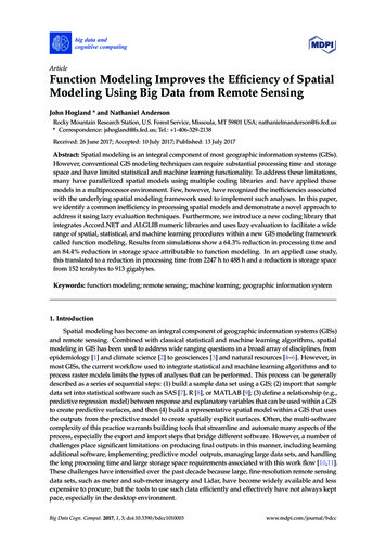
POLIMERY 2013, 58, nr 4276JAIME HORTA RANGEL1,2), WITOLD BROSTOW2),*), VICTOR M. CASTANO1,3)Mechanical modeling of a single-walled carbon nanotubeusing the finite element approachSummary — An analytical procedure to determine the elastic modulus of a single-walled carbonnanotube of armchair type is presented. The interacting forces between atoms are determinedbased on potentials derived from quantum mechanics. For the axial stretching, the Morse potentialparameters were used, along with the bending potential. The model associates a hexagonal latticewhere the nodes correspond to atoms and bars to the links (bonds) between them. The finite element model considers fixed position of one end while the tension forces are applied at the otherend. The result of the simulation is the shape of the deformed nanotube and its elastic modulus.The influence of the overall dimensions of the nanotube on the modulus of elasticity was alsoexamined.Keywords: nanotechnology, carbon nanotubes, computer modeling, bond stiffness, advancedmaterials.MECHANICZNE MODELOWANIE JEDNOŒCIENNYCH NANORUREK WÊGLOWYCHMETOD ELEMENTÓW SKOÑCZONYCHStreszczenie — W artykule opisano procedurê analityczn¹ wyznaczania modu³u sprê¿ystoœci jednoœciennych nanorurek wêglowych o strukturze fotelowej. Si³y oddzia³ywania miêdzy atomamiwyra¿ono za pomoc¹ potencja³ów wprowadzonych na gruncie mechaniki kwantowej. Do opisuosiowego rozci¹gania i zginania u¿yto potencja³u typu Morse’a. Model tworzy heksagonalna siatka, w której wêz³y odpowiadaj¹ atomom, a linie wi¹zaniom miêdzy nimi. Metodê elementówskoñczonych zastosowano do przedstawienia nanorurki, której jeden koniec jest unieruchomiony,podczas gdy do drugiego koñca przy³o¿one s¹ si³y rozci¹gaj¹ce. Wynikiem symulacji jest kszta³tzdeformowanej nanorurki i jej modu³ sprê¿ystoœci. Zbadano równie¿ wp³yw ogólnych wymiarównanorurki na modu³ sprê¿ystoœci.S³owa kluczowe: nanotechnologia, nanorurki wêglowe, modelowanie komputerowe, sztywnoœæwi¹zañ, materia³y zaawansowane.Carbon nanotubes (CNTs) were identified in 1991 byIijima as a graphitic carbon hollow structure resemblingelongated fullerenes comprised of interconnected hexagons of carbon atoms spanning the entire surface of thenanotube. The ends have the form of half-dome shapedfullerene molecules as a result of topological defects suchas pentagonal and heptagonal defects near the tube ends[1]. The spatial orientation of the hexagons is not fixed,which can lead to „chiral” as well as „achiral” CNT configurations. CNTs can be categorized as single-wallednanotubes (SWNTs) or multi-walled nanotubes(MWNTs) [2].1)State University of Queretaro, Queretaro, Mexico.2) Laboratory of Advanced Polymers and Optimized Materials, Uni-versity of North Texas, USA.The National Autonomous University of Mexico, Mexico.*) Corresponding author: wbrostow@yahoo.com3)Knowledge of the mechanical behavior of carbonnanotube composites requires the identification of theelastic properties and fracture as well as the interactionwith the matrix phases, of the nanotubes themselves. Inturn, the properties of nanotubes depend on their atomicarrangement, whether they are of the zig-zag, the armchair or the chiral type, as well as on their specific dimensions. Nanotubes are the known natural objects mostsimilar to the ideal reinforcing fiber, due to their strengthand high aspect ratio.Generally speaking, carbon nanotubes are graphenesheets rolled into a cylinder [3] (see Figures 1 and 2) andare known to have excellent physical and mechanicalproperties combined with low density, which make themideal candidates for composite reinforcements [3, 4]. Theusual analytic approach reported in the literature is notunlike the case of conventional fibers, the scale of reinforcement, however, involves changing from microns tonanometers, which represents a wholly different situation. Indeed, the morphology of the nanotubes, at the
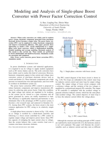
POLIMERY 2013, 58, nr 4a)277b)basic chemistry, but their properties are very differentand there is a lack of fundamental understanding of thedetailed nanostructure-mechanical properties relationship.Accordingly, the present work is aimed to, first, simulate the mechanical characteristics of arm chair carbonnanotubes, starting from the basic geometry at the nanoscale and, second, to investigate the influence of the dimensions of the nanotubes on their final modulus.c)PROPERTIES OF A SINGLE-WALLED NANOTUBEFig. 1. The structure of: a) graphene sheet, b) fullerene, c) carbon nanotubea)b)c)It has been determined that the distance between carbon atoms (r) is about 0.14 nm [3], while the diameter ofthe nanotubes varies between 0.4 to 2.5 nm. Maximum resistance to stress has been evaluated around 30 GPa [5].The axial stretching Morse potential between carbonatoms is defined as follows [7]:F(Dr) 2bDe(1 – e–bDr)e–bDrwhere: F — the axial force between carbon atoms, Dr r – r0 —stretch which is a difference between current and equilibriumdistance between carbon atoms (see Figure 3), De — the dissociation energy, b — a constant which describes the potential ofatoms interaction.a)b)rFig. 2. Basic geometrical arrangements of carbon nanotubes:a) armchair, b) zig-zag, c) chiralnanoscale, has been found to generate important changesin the mechanical behavior. For instance, there are reportswhere the modulus of elasticity depends on the atomictopology, either zig-zag, chiral, etc. Furthermore, the formation of nanotubes in layers also generates significantvariations in their final mechanical behavior.Several experimental studies have determined thatthe elastic modulus of a nanotube layer is of the order of1 TPa, that is, orders of magnitude larger than conventional engineering materials, such as steel [4, 5]. Moreover, their structure leads to a high stiffness under tensilestress and remarkable bending properties, with a hugepercentage of elongation prior to failure. In the early 80’sKroto et al. [6] developed the basics of fullerene chemistry, geometrical structures formed by carbon atoms arranged in hexagonal and pentagonal nanometer rings.Interestingly from the materials science standpoint, fullerenes, carbon nanotubes and graphene share the same(1)DrqDqFig. 3. Interaction between C-C atoms: a) axial stretching,b) angular stretchingAccording to Belytschko [8] b 26.25 nm-1, De 6.031 · 10-10 N · nm, r0 0.139 nm. By substituting parameters, we obtain:F 317·10–10(1 – e–26.25 Dr)e–26.25 Dr(2)Figure 4 shows the behavior of bond stiffness. C-Cbonds in compression require a big force to stretch them,while the stretch increases, the associated force growsrapidly and tends to infinity (asymptotic value). Figure 5shows the bond stretching for the range analyzed. On theother hand, according to [7], the momentum-angle relationship under flexion is:M(Dq) kqDq[1 3ksextic(Dq)4](3)where: M — the angular free (moment) development betweencarbon atoms, Dq q – q0 — a difference between currentand equilibrium bond angle (with q0 2.094 rad), kq 0.9 · 10-18 N·m/rad2 — the angular force constant of the minimum of the well, ksextic 0.754 rad-4.
POLIMERY 2013, 58, nr 4278Fig. 4. Force of bond stiffness of carbon atomsBy substituting values of these parameters, to eq. (3)we obtain:M(Dq) 0.9·10–18 Dq[1 2.262 (Dq)4](4)The angle variation Dq is expressed in radians, Moment M units are in nm. Figure 6 shows a plot obtainedaccording to eq. (4).EQUIVALENT MECHANICAL STRUCTURAL MODELAxial stiffness (K) for bonds in the range indicated ischaracterized with a lineal approach (Figure 5):K (axial and angular) difference value forces//difference bond stretching valuesFig. 6. Relationship between bending flexural moment andbending angle (q) in wide range (a) and range of current analysis (b)(5)For compression load corresponding value isK c 1.1185 · 10 -6 N/nm and for tensile load K t 0.5845 · 10-6 N/nm. For the range analyzed in this work,the angle dependence of bending stiffness Kq M/q isclearly lineal (Fig. 6).Substituting values, we obtain: Kq 0.9 · 10-9 N · nm.From the perspective of structural mechanics, the baraxial stiffness was assessed by the expression:Ka AE / L(6)where: A — the cross section area of the bar, E — the modulusof elasticity of the material, L — the length of the bar.Similarly, the bending stiffness of a beam is evaluatedusing the formula:Kq 4 EI / L(7)where: I — the moment of inertia of the section.However, it is necessary to consider that in the expression proposed by Belytshko [8] angle q is generated withthe participation of two links (C-C-C atoms arrangement). So, to ensure the compatibility relation it shouldbe considered a half of the angle q. Therefore:Kq 2 EI / L(8)Relations (7) and (8) we rewrite considering the belowobtained values for Kc, Kt and Kq.Fig. 5. Force of bond stiffness of carbon atoms — range of theanalysis(AE / L)c 1.1185·10–6(AE / L)t 0.5845·10–6(9)(2 EI / L)q 0.9·10–9(10)
POLIMERY 2013, 58, nr 4279We assume a circular bars cross section, i.e. A pd2/4and I pd4/64. By substituting these expressions to eqs.(9) and (10) we obtain:[(pd2 / 4)E / L]c 1.1185·10–6[(pd2 / 4)E / L]t 0.5845·10–6(2 E / L)(pd4 / 64)q 0.9·10–9(11)(12)These equations we can write in terms of relations E/L.In the cases of compression and bending, we have:(E / L)c 4·1.1185·10–6 / pd2(E / L)q 32·0.9·10–9 / pd4(13)Solving eqs. (13) for area and diameter associated byfulfilling both conditions we obtain:dc 0.08 nmAc 0.005 nm2(14)Similarly, for the tension case, we have:dt 0.111 nmAt 0.00968 nm2(15)These results allow as obtaining the stress-strain relationship (Figure 7). We can also obtain the modulus ofelasticity E for bonds under compression as well underFor axial effects Wan and Delale [7] suggest the thicknessof the nanotube equal to 0.34 nm, while in bending0.089 nm. Our case is more associated to axial effects but,when we take the diameter of nanotubes equal to 0.6 nmthe wall thickness of 0.34 nm is bigger than the diameter.So we will consider for our purposes the thickness equalto 0.2 nm.ANALYTICAL MODELThe analytical model applied is derived from the fieldequations of continuum mechanics for a linear elastostatic problem [12]:S 2nE ltrE ( I )E 1( u uT )2Div S b ru&&(17)where: E — infinitesimal strain tensor; S — stress tensorPiola-Kirchhoff; ü — displacement vector; n, l — Lame constants; I — identity tensor; b — body force; r — density.By applying the variational principle of minimum potential energy [13], we obtain the following matrix equation:ò[ B]T [ D][ B] dv {U } ò [ N ]T { p} dA ò [ N ]T {b} dv {P}AV(18)where: [B] — matrix of shape function derivatives, [D] — matrix of elastic constants, [N] — shape function matrix, {U} —displacement vector, {p} — vector of external pressures, {b} —vector of body forces, {P} — vector of punctual external loads.The first integral is associated with the deformationenergy of the system, while the others are integrals of theload vector. This is the model to study the mechanicalbehavior of the nanotube, assumed as a beam lattice. Thebeams are modeled with finite element 3-D beams with6 degrees of freedom per node.Fig. 7. Stress-strain relationship in the analysis interval —bilineal behavior of modulus Ea)b)tension load. The resulting elasticity moduli are asfollows:Etension 913·10–8 N/nm2Ecomp 3070·10–8 N/nm2(16)It is possible to simulate other bond deformations, torsion, out-of-plane angle variations, but in agreement with[9—11] these effects are negligible under the small strainconditions applied in this analysis. Van der Walls forcesand electrostatic forces were not considered.To find the elasticity modulus of the whole nanotubewe will use the thickness of the equivalent grid nanotubemodel. This model has two beam areas, one for stretchedbeams and another for compressed ones (eqs. 14 and 15).Fig. 8. Lattice model of single-walled carbon nanotube (a) andapplied boundary conditions on the nanotube (b)
POLIMERY 2013, 58, nr 4280The atoms are placed in the positions of the nodes andthe bars are assigned with the rigidity and dimensionsabove indicated to generate the lattice (atomistic model)with force (potential) between them. The analysis wasperformed using the ANSYS modeling program [14], alsogenerating a parametric program in APDL language thatallows us to realize all mechanical required analysis. Theboundary conditions of the whole nanotube are chosen atthe ends, all nodes of one end are restricted in the threemean directions. The forces are applied at nodes of theother end of the nanotube (see Figure 8).The first analysis was performed for an armchairnanotube, with diameter 1.0 nm and length 8.0 nmwith the aspect ratio L/D 8. The length of the links (bars)is 0.14 nm. According to Ghasemzadeh and Jalalabad [15]we take the poisson’s ratio as 0.16. Because it is not possible to know a priori which bars (bonds) experience tension or compression, the analysis was performed in twostages. The first is detecting the kind of stress to whichthey are subjected. In the second stage, each bar is assigned the appropriate area and modulus of elasticity.We obtain for this case An 0.628 nm2, the modulus ofelasticity of the whole nanotube is then obtained as E 0.8 TPa, equal to the experimental report obtained byRossi and Meo [9] for such a nanotube. The analysis of thestress of armchair type nanotube with a bar structuralmechanical model turns out to be a practical and efficientapproach to evaluate the performance of the nanotubewhen subjected to different mechanical stresses. Here, wehave taken into account tension load, however, it is possible the apply other effects, including the case of dynamical stability, which will be reported separately. The influence of the overall dimensions of this nanotube: diameterand length, was presented in Table 1. It can be observedhow the aspect ratio does not affect seriously the mechanical ability of the nanotube, even for high values of theaspect ratio (Figure 10). Figure 11 shows the deformedconfiguration for L/D 30.In order to see this influence of diameter on the valueof the modulus of the nanotube, we performed a series ofanalyses with the fixed value of nanotube length of10.0 nm. We varied the diameter accordingly. The resultsRESULTS AND DISCUSSIONThe simulations allow us to observe the behavior under a tensile force for a single-walled carbon nanotube ofarmchair type. The force applied was increased until itreached a value close to Fn 1.0 · 10-8 N. Figure 9 showsthe displacement of the nanotube in nanometers. To evaluate the elastic modulus of the whole nanotube, we takethe maximum axial displacement in z direction equal to0.158 nm. Thus, the deformation is ez 0.02. To evaluatethe maximum stress in the nanotube, we divide the finalforce (Fn) applied by the nanotube cross section area:An pDnt(19)where: Dn — the diameter of nanotube, t — the diameter ofnanotube equal to 0.2 nm.Fig. 10. Effect of aspect ratio (L/D) on modulus E (here D wasfixed at 1.0 nm)Fig. 9. Deformed shape of a single-walled carbon nanotube —displacements Z-direction in nanometers (L/D 8)Fig. 11. Deformed shape of a single-walled carbon nanotube ofarmchair type (L/D 30)
POLIMERY 2013, 58, nr 4281Fig. 12. Modulus E versus diameter of nanotube (D) (length ofnanotube was fixed at 10 nm)are shown in Table 2 and Figure 12. Interestingly, themodulus of elasticity (E) has a decreasing harmonic behavior. For higher values of nanotube diameter, themodulus E approaches 0.9 TPa. Finally, Figure 13 showsthe behavior of the nanotube deformed for values L 10 nm and D 2.0 nm.T a b l e 1. Influence of aspect ratio (L/D) on modulus (E)L/DD, nmL, nmE, 0.813141140.802161160.805201200.811301300.806T a b l e 2. Influence of diameter of nanotube (D) on modulus (E)L, nmD, nmE, 847101.60.940101.80.867102.00.940CONCLUDING REMARKSThe outstanding mechanical properties of carbonnanotubes and their potentially massive use as reinforc-Fig. 13. Deformed shape of a single-walled carbon nanotube ofarmchair type (L 10 nm, D 2.0 nm)ing agents, make mandatory a clear understanding of themechanisms that lead to their unique properties, beginning at the nanoscale level. The simulations we have performed indicate, first, that the lattice model can remarkably reproduce the experimental values reported by various groups and, second, that the mechanical propertiesseem to be a scalable factor of these fascinating materials.The investigations concerning dynamic behavior of suchsystems, by using the same approach reported herein, iscurrently under way and will be reported separately.REFERENCES1. Li Lingyu, Li Bing, Hood M. A., Li Ch. Y.: Polymer 2009, 50,953.2. Harris P. J.: „Carbon nanotubes and related structures”,Cambridge University Press 1999.3. Dresselhaus M. S.: Annu. Rev. Mater: Sci. 1997, 27, 1.4. Terrones M.: Annu. Rev. Mater. Res. 2003, 33, 419.5. Treacy M. M. J., Ebbesen T. W., Gibson J. M.: Nature 1998,381, No. 20, 678.6. Kroto H. W., Heath J. R., O’Brien S. C., Curl R. F., SmalleyR. E.: Nature 1985, 318, 162.7. Wan H., Delale F.: Meccanica 2010, 45, 43.8. Belytschko T., Xiao S. P., Schatz G. C., Ruoff R. S.: Phys. Rev.B: Condens. Matter. 2002, 65, 235 430.9. Rossi M., Meo M.: Compos. Sci. Technol. 2009, 69, 1394.10. Govindjee S., Sackman J. L.: Solid State Commun. 1999, 110,227.11. Lu J. P.: J. Phys. Chem. Solids 1997, 58, 1649.12. Gurtin M.: „Continuum Mechanics” Academic Press 1981.13. Cook R. D., Malkus D. S., Plesha M. E.: „Concepts and application of finite element analysis”, John Wiley & Sons Inc.,New York 1988.14. Ansys, Inc. Software, ver 11, 2009, Canonsburgh PA, USA.15. Ghasemzadeh H., Jalalabad E. A.: Int. J. Civil Eng. 2011, 9,No. 3, 223.Received 18 V 2012.
conditions applied in this analysis. Van der Walls forces and electrostatic forces were not considered. To find the elasticity modulus of the whole nanotube we will use the thickness of the equivalent grid nanotube model. This model has two beam areas, one for stretched beams and another for compressed ones (eqs. 14 and 15).