Transcription
USER MANUALTMT-ST10SOLDERING TIP TESTERwww.thermaltronics.com
TABLE OF CONTENTSTMT-ST10 SPECIFICATIONS. 1INTRODUCTION. 1SYSTEM FEATURES. 2CONTROL PANEL. 3UNPACKING/ASSEMBLY/OPERATION. 4-5SOFTWARE FUNCTIONALITY. 6CALIBRATION. 7-8ORDERING GUIDE. 9WARRANTYAll equipment and accessories are warranted by Thermaltronics to be free fromdefects in materials and workmanship as follows:Part LE-1DescriptionSolder Tip TesterGround Wire (EU Plug)Ground Wire (US Plug)Ground Wire (CN Plug)Mini USB Data CableWarranty Period1 Year30 Days30 Days30 Days30 DaysThis warranty does not apply to equipment or goods which have been tamperedwith, misused, damaged through improper installation or used in a mannercontrary to supplier instructions. Normal “wear and tear” of equipment or goodsis not covered by this warranty. If the product should become defective within thewarranty period, Thermaltronics will repair or replace it free of charge at its soleoption. Warranty period is from the date of purchase by the original owner. If thedate of purchase cannot be substantiated the date of manufacture will be used asthe start of the warranty period.WARNING:This appliance is not intended for use by persons (including children) with reduced physical, sensory or mentalcapabilities, or lack of experience and knowledge, unless they have been given supervision or instructionconcerning use of the appliance by a person responsible for their safety.Children should be supervised to ensure that they do not play with the appliance.
USER MANUALTMT-ST10 SPECIFICATIONSInput Line Voltage:Temperature Test Range:Temperature Resolution:Temperature Accuracy:Voltage Test Range:Voltage Resolution:Voltage Accuracy:Resistance Test Range:Resistance Resolution:Resistance Accuracy:Thermal Sensor:Size (W x H x D):Weight:LCD display:USB port:Data Storage:Certification Marks:DC 9V Battery0 C - 600 C / 32 F - 1200 F1ºC / 1ºF 3ºC (300 to 600ºC) 5ºC (other than above)0 - 100 mV (AC)0.1 mV (AC) (5% of reading 1 digit)0 - 100 Ω0.1 Ω (5% of reading 1 digit)K Type Thermocouple (ST-SNSR-1)85mm x 175mm x 48mm0.35 KG48mm x 26.5mmMini USB port32,640 EventsCEINTRODUCTIONCongratulations on your purchase of the TMT-ST10 solder tip tester. Thisunit has been tested and inspected by Thermaltronics prior to shipment, andwith proper maintenance will give you years of reliable performance.SYSTEM FEATURESThe TMT-ST10 is a multifunction soldering tip tester, it has the followingmeasurement functions: Tip temperature ( C/ F switchable) Tip to ground resistance (ohm Ω) Tip to ground leakage (mV)1TMT-ST10 Solder Tip Tester
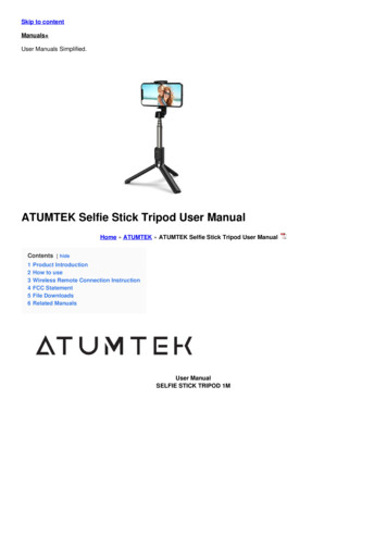
SYSTEM FEATURES(2) LCD Display(1) Power Switch(3) Mini USB Port(8) Function Buttons(4) Ground Connection Socket(7) Sensor Release Lever(5) Test Plate(6) Thermal SensorFunctions & Features(1) Power Switch - Move up to switch ON, move down to switch OFF. The tester will automaticallygo into sleep mode if not in use for 300 seconds.(2) LCD Display - Displays test parameters and info messages. (see: Control Panel - LCD Display)(3) Mini USB Port - Use the mini USB cable (ST-CABLE-1) to connect the TMT-ST10 to acomputer in order to read stored test data.(4) Ground Connection Socket - For use when testing Tip to ground resistance (ohm) and tip toground leakage. Use the Ground Cable to connect the TMT-ST10 to the power strip or socket, towhich the soldering iron is connected.Note: The tester must share the same ground as the soldering iron.(5) Test Plate - Touch the Soldering Tip on the test plate to begin testing for Tip to groundresistance (ohm) or Tip to ground voltage (mV) .(6) Thermal Sensor - To test temperature, touch the thermal sensor with a soldering iron tip. Do notpush hard. If the sensor is damaged or oxidized it can be changed by pulling down the (7) SensorRelease Lever, and then removing and replacing with a new sensor.Note: Make sure that the sensor polarity Red (left) and Blue (right) are not reversed.(7) Sensor Release Lever - Pull down on the lever to remove and replace the thermocouple.(8) Function Buttons - Allows operation of the tip tester including configuration, test mode selectionand saving test data. (see: Control Panel - Function Buttons)www.thermaltronics.com support email: support@thermaltronics.com2
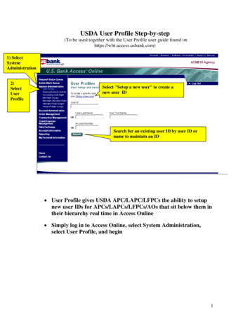
USER MANUALCONTROL PANEL(a) Current Test Data(b) Tester Memory(c) Info Display(d) Reset Button(e) Hold Button(f) Select Button(h) Save ButtonLCD DisplayThe display has three rows of data.(a) Current Test Data - Row 1 - Shows the current test data in large characters.(b) Tester Memory - Row 2 - Shows the current saved data in temporary memory. It is divided into3 segments: temperature, tip to ground resistance and tip to ground leakage.All segments showing data are temporarily held in the tester memory, however if no data isrecorded, the segment will show "---".(c) Info Display - Row 3 - Shows info messages such as notices and alerts. If no info message isdisplayed, the date & time in YY-MM-DD HH:MM format will be shown.Function Buttons(d) Reset Button has different functionality in different modes: In Temperature mode, pressing "RESET" will toggle display between C and F. In Tip to Ground Resistance mode (ohm), pressing "RESET" will reset (a) Current Test Data tozero. Note: Restarting the test meter will clear the calibration. In Tip to Ground Leakage mode (mV), pressing "RESET" will reset (a) Current Test Data tozero. Note: Restarting the test meter will clear the calibration.(e) Hold Button - pressing the "HOLD" button will instruct the tester to display only the maximumtest value. Press "HOLD" again to release hold mode.(f) Select Button - pressing the "SELECT" button toggles the test mode between Tip Temperature,Tip to ground resistance (ohm) and Tip to ground leakage (mV).(g) Save Button has different functionality based on the length of time the button is pressed held. Short Click - pressing and holding the "SAVE" button for less than 3 seconds saves the (a)Current Test Data to (b) Tester Memory (LCD Display Row 2). Long Press - pressing and holding the "SAVE" button for more than 3 seconds will save thedata from (b) Tester Memory to data storage. Afterwards the data can be downloaded to acomputer through the mini USB port.3TMT-ST10 Solder Tip Tester
UNPACKING/ASSEMBLY/OPERATIONPlease read this manual and follow the directions before using the equipment.The carton contains:1. Instruction manual2. TMT-ST10 Solder Tip Tester3. ST-SNSR-1 K Type Thermocouples (10 Pack)4. ST-GWIRE Ground Wire (Power Plug style will depend on region)5. ST-CABLE-1 Mini USB CableImportant: Keep all shipping materials until satisfactory operation has been verified.Assembly1. Remove TMT-ST10 solder tip tester from its box and place on a suitable work bench.2. Install a 9V battery into the back of the test meter.3. Remove the ST-SNSR-1 K Type Thermocouples from the box. Place one thermocouple on the (6)Thermal Sensor. Ensure that the sensor polarity Red (left) and Blue (right) are not reversed.4. Optional: Remove the Ground Wire from the box. If voltage or resistance testing is needed,connect one end to the (4) Ground Connection Socket. Connect the other end to the power stripor socket, to which the soldering iron is connected. (see: System Features)5. Optional: Remove the ST-CABLE-1 Mini USB Cable from the box. If test data output to computeris needed, connect one end to the (3) Mini USB Port. Connect the other end to the computerUSB port and install data output software. (see: Software Functionality)6. Switch the (1) Power Switch to the “on” position, the Thermaltronics Logo will display, followedby the software revision number.7. The tester is now ready to use.Test ohm and mVSensor Release LeverTest TemperatureSensor (Red Polarity)Sensor (Blue Polarity)www.thermaltronics.com support email: support@thermaltronics.com4
USER MANUALUNPACKING/ASSEMBLY/OPERATIONOperation - Test Temperature1. Turn on the TMT-ST10 tip tester.2. The tip tester will default to Tip Temperature Test mode.3. Press the "RESET" button to switch between Celsius (C) and Fahrenheit (F) display.4. To test temperature, touch the solder tip onto the (6) Thermal Sensor. Allow a few seconds forthe reading to stabilize. Note: Do not push down forcefully with the solder tip as it maydamage the thermal sensor.5. Click the "SAVE" button to save the tested value to (b) Tester Memory.Operation - Test Tip to Ground Resistance1. Turn on the TMT-ST10 tip tester.2. Press the "SELECT" button once to toggle to the Tip to Ground Resistance (ohm) test mode.3. Connect one end of the ground wire (ST-GWIRE) to the (4) Ground Connection Socket.Connect the other end to the power strip or socket, to which the soldering iron is connected.Note: The tester must share the same ground as the soldering iron.4. To test Tip to Ground Resistance (ohm), place the solder tip onto the (5) Test Plate. Allow a fewseconds for the reading to stabilize.5. Click the "SAVE" button to save the tested value to (b) Tester Memory.Operation - Test Tip to Ground Leakage1. Turn on the TMT-ST10 tip tester.2. Press the "SELECT" button twice to toggle to the Tip to Ground Leakage (mV) test mode.3. Connect one end of the ground wire (ST-GWIRE) to the (4) Ground Connection Socket.Connect the other end to the power strip or socket, to which the soldering iron is connected.Note: The tester must share the same ground as the soldering iron.4. To test Tip to Ground Leakage (mV), place the solder tip onto the (5) Test Plate. Allow a fewseconds for the reading to stabilize.5. Click the "SAVE" button to save the tested value to (b) Tester Memory.Operation - Saving Test Data1. Ensure that at least one test parameter is saved to (b) Tester Memory (LCD Display Row 2)2. Long Press the "SAVE" button for 3 seconds to save the test data from (b) Tester Memory tolong term data storage which can be downloaded to a computer at a later time.3. If save is successful the (c) Info Display will show the message "Saved to memory"5TMT-ST10 Solder Tip Tester
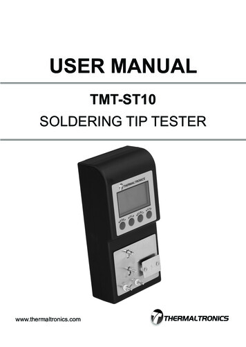
SOFTWARE FUNCTIONALITY(2) Browse Button(1) Output File(5) Options(3) COM Port(4) Read RecordsFunctions & FeaturesThe TMT-ST10 Data Output software allows test data to be downloaded from the tester and tester date and time tobe synched with the computer date and time.(1) Output File - directory and filename of output data file(2) Browse Button - Browse and select the directory to save the output file to.(3) COM Port - The port that the TMT-ST10 tip tester is connected to on the computer.Note: The software will automatically search for the COM port when tip tester is connected to the computer(4) Read Records - Displays how many records have been read from the tip tester saved memory.(5) Options - To select an option, click the checkbox next to the option text. Clear tip tester memory after downloading and saving - if selected TMT-ST10 memory will be cleared after testdata has been downloaded to the computer. Sync tip tester date and time after download - if selected TMT-ST10 date and time will be synched to the computerdate and time.Operation - Retrieving Test Data1. Turn on the TMT-ST10 tip tester.2. Use the mini USB cable (ST-CABLE-1) to connect the TMT-ST10 to a computer through the (3) Mini USB Port.3. Run TMT-ST10 Data Output software.4. Note: Only select (5) Options - Clear tip tester memory after downloading and saving if you want to clear the tiptester memory after downloading to computer.5. Click "BROWSE" button to select the filename and output directory.6. Click "Start".Operation - Setting the Date / Time1. Turn on the TMT-ST10 tip tester.2. Use the mini USB cable (ST-CABLE-1) to connect the TMT-ST10 to a computer through the (3) Mini USB Port.3. Run TMT-ST10 Data Output software.4. Select (5) Options - Sync tip tester date and time after downloading and saving.5. Click "Start Download".6. The tip tester data and time will sync to the computer date and time after completion of the download.www.thermaltronics.com support email: support@thermaltronics.com6
USER MANUALCALIBRATIONEquipment and Parts Required Precision standard power supply ST-GWIRE-1 Mini USB Cable Computer running Windows XP or higherImportant Notes Before Calibration Verify that the ST-SNSR-1 thermocouple sensor is installed on the tip tester beforeturning on the unit. Otherwise test accuracy will be affected. Please make sure the thermocouple sensor is at room temperature. Whenever theTMT-ST10 is turned on (LCD Display shows “ Welcome”), the TMT-ST10 will selfcalibrate it’s reference temperature point.Calibration Procedure1. Verify that a new ST-SNSR-1 thermocouple is attached onto the TMT-ST10.2. Turn on the TMT-ST10 tip tester.3. Verify that the tip tester is in Temperature testing mode.4. Take off the ST-SNSR-1 thermocouple from the TMT-ST10 tip tester5. Set the precision power supply output to V 20.64mV. (This voltage is thethermoelectric voltage of the K type thermocouple at 500 C)6. Connect the V 20.64 mV from the precision power supply to two connectors on thetip tester as follows: Left connector is positive ( ) voltage Right connector is negative (-) voltage7. The TMT-ST10 LCD will now display the temperature as:T1 500 C Current room temperature If this value is within 3 C of the defined temperature range then no calibration isnecessary. If this value is more then 3 C over the defined temperature range then the unit willneed to be calibrated. (Please follow steps “Calibrating the Temperature”)7TMT-ST10 Solder Tip Tester
CALIBRATIONParityBaud RateDataBitsInput ASCEnter Commands hereStop BitsShow ASCCalibrating the Temperature1. Change the voltage on the precision power supply until the display temperature comes within 3 C of the definedtemperature range as follows: If the display temperature is lower then the defined temperature then decrease the voltage value set on theprecision power supply until the temperature is correct. If the display temperature is lower then the defined temperature then decrease the voltage value set on theprecision power supply until the temperature is correct.Note: Please make a note of this voltage value as it will be used later to calibrate the tester.2. Use the mini USB cable (ST-CABLE-1) to connect the TMT-ST10 to a computer through the Mini USB Port.3. Run program commix.exe series port management program found on the installation cd4. Select the correct settings as follows: Baud Rate 9600 DataBits 8 Parity None Stop Bits 1 Input ASC Show ASC5. Select the correct COM Port and press “Open Port” to open the serial port. If the wrong port is select an error message “Open Port Failure” will appear. If the correct port is selected the “Open Port” button will change to “Close Port”.6. Input the commands as follows and press the “Send” Button.Note: XX.XX is the set voltage from step 1CommandCommand descriptionTMT-ST10 Response#LINK\CREstablish link to TMT-ST10LINK OK\CR#SET TmV XX.XX\CR Calibrate the thermocouple voltage output to SET OK\CRXX.XX (Must be in Temperature mode)Example:Command#LINK\CR#SET TmV 20.64\CRCommand descriptionTMT-ST10 ResponseEstablish link to TMT-ST10LINK OK\CRCalibrate the thermocouple voltage output to SET OK\CR20.64 (Must be in Temperature mode)7. Your tip tester is now calibrated.www.thermaltronics.com support email: support@thermaltronics.com8
ORDERING GUIDETMT-ST10THERMALTRONICS SOLDER TIP TESTERPART E-2ST-GWIRE-3DESCRIPTIONSolder Tip TesterMini USB CableTemperature Sensors (10 Pack)Ground Wire (EU Plug)Ground Wire (US Plug)Ground Wire (CN Plug)www.thermaltronics.com support email: support@thermaltronics.com9
Support Email: support@thermaltronics.comwww.thermaltronics.com
Sync tip tester date and time after download - if selected TMT-ST10 date and time will be synched to the computer date and time. Operation - Retrieving Test Data 1. Turn on the TMT-ST10 tip tester. 2. Use the mini USB cable (ST-CABLE-1) to connect the TMT-ST10 to a computer through the (3) Mini USB Port. 3. Run TMT-ST10 Data Output software.