Transcription
Krautkrämerultrasonic transducersFor flaw detection and sizing
Quality at every stepFor 70 years, Krautkrämer ultrasonic transducershave been synonymous with quality.Our core ability is to match ultrasonic probes to the inspectionapplications of today, both simple and complex. This skilllets allows us to design and manufacture fine-tuned qualityprobes that meet your customer-specific requirements.We build quality into every step we perform—from startto finish: Requirement analysis. At the very beginning of ourdiscussions with you, we draw on our experiencemanufacturing more than 1 million probes—including 14,000probe variations—to build quality into our requirementanalysis process. Specifications. To help ensure quality results, each product inour one-stop-shop adheres to our exacting specifications. Simulation. Early in the process, we use industry leadingsimulation technology software to help us determine whatneeds to be done to meet application requirements. Wealso understand the boundaries of simulation and how thatimpacts the build. Feasibility studies. We support challenging applications byconducting feasibility studies in our labs, which are locatedworldwide. Send us your samples and we can determine thebest inspection method and technology. Material selection and processing. We use the higheststandards when sourcing our raw materials, andour in-house manufacturing is fully controlled to ISOstandards. Our ceramics shop in Shannon, Ireland, createspiezocomposite ceramics, an in-house offering unique toour business. Prototyping. With a strong understanding of your needs, weoffer prototyping to further validate that the solution works. Product validation. With an emphasis on repeatability andprocess stability, our exacting build-and-test proceduresand specifications are followed for every single build,meaning every step includes a quality inspection/test tomeet required criteria. What’s documented: Each probe hasa unique serial number, and every validated manufacturingstep is recorded before shipment. Finally, our databasestores historical test data for every probe. We provide acertification of conformance, including probe waveform andfrequency spectrum results with each probe. Manufacturing. With manufacturing available in both Europeand the USA, we can provide local variation and meet localnorms. In fact, we can customize your transducer to meetyour specific ultrasonic testing applications. Modificationscan involve transducer case design, connector options, andelement size and shape, including non-standard frequencies,sensitivity, bandwidth and focusing. Delivery. Our pledge is to provide you with exceptionalproduct availability with our global distribution sites andcustomer care resources, to ensure that order status iscommunicated until your probe reaches your door. Support. We have expert resources available to help youwith your ultrasonic inspection challenges including fieldapplication engineers and remote service technicians whocan be reached through phone or email 24/7. Our probesare backed by a standard one year repair or replacewarranty as a testament that we stand behind our products.Krautkrämer ultrasonic transducers from InspectionTechnologies deliver consistent readings. Our quality goesbeyond standard, our pricing is competitive, and our productsare delivered when and where you need them.Now that’s quality, every step of the way.
Contents05Transducer selection criteria and performanceGeneral information—contact inspection and immersion methodsTransducer selection criteria—european standardsTransducer selection criteria—north american standards08Contact transducersStraight beam contact transducers, protective faceStraight beam contact transducers, wear resistantStraight beam contact transducers, delay lineStraight beam contact transducers, dual elementAngle beam transducers—large sizesAngle beam transducers—small sizesAngle beam transducers—dual element33Immersion transducersEuropeanNorth American38Transducers for specific applicationsSpecial application transducersPhased array transducers40Transducer accessoriesCables and adaptersCouplantsCalibration blocksTransducer kits44 Transducer certification45 Tables and formulas
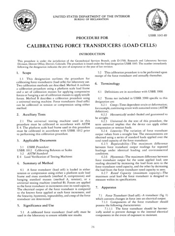
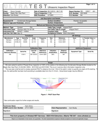
Transducer selectioncriteria and performanceGeneral informationThe ultrasonic transducers in this catalog are divided into twogeneral categories, Contact and Immersion.Transducers for the contactinspection methodStraight beam—single element Parts with regular geometry andrelatively smooth contact surface Flat or curved contact surface Flaw or backwall parallel tosurface or detectable with beamnormal to surface Preferred for penetration ofthick sections Delay line types improve nearsurface resolution Requires couplant layer, typically agel, oil, or paste Typically used for manual inspectionStraight beam—dual element (TR) Transmit and receive elementsseparated by crosstalk barrier Flaw or backwall parallel tosurface or detectable with beamnormal to surface Best for thin sections, near surfaceresolution Requires couplant layer, typically agel, oil, or paste Typically used for manual inspectionAngle beam Element mounted on integral orreplaceable wedge Uses refraction to transmit shear orlongitudinal wave at apredetermined angle Most standard transducers generateshear waves by mode conversion Preferred for parts with inclined flaws,such as welds Available in both single and dualelement types Requires couplant layer, typically agel, oil, or paste Sometimes used in mechanized orautomated testingTransducers for the immersion methodImmersion transducers Acoustically matched for best efficiency in water Suitable for parts with irregular geometries Commonly used in mechanized or automated testing Best method for consistent coupling andreproducible results Large parts can be tested using probe holders, bubblers,or water jets Transducers can be focused to improve resultsFocused immersion transducers Spherical focus forms a point or spot Cylindrical focus forms a lineSpherical(Spot, point) focusCylindrical(Line) focusAdvantages of focusingIncrease sensitivity to small flawsImprove signal-to-noise WaterInterfaceSound beamFlawFlawFlawImprove near surface resolutionTest pieceCorrect for contoured surfaces5
Transducer selection criteria—European standardsFor transducers manufactured to European standards, technical and performance information isprovided throughout this catalog based on the definitions below. A comprehensive data sheet is suppliedwith most flaw detection transducers at no charge.DescriptionExplanationDiameter D or length x width a x b of the transducer element. The size of the element strongly affects the shapeElement size D or a x b of the transmitted sound field. Slight deviations, (e.g., imperfect shape or positions with reduced radiation dueto poor bonding) cause considerable evaluation errors, even when calibrated to a reference flaw.Nominal frequency fThe mean frequency of all probes of the same type. The frequency has a great influence on the evaluationof reflectors. Even the shape of the sound field and the reflection behaviour of angled reflectors are stronglydependent on the frequency. With increasing frequency, the echo height from non-vertically positionedreflectors to the sound beam decreases. This is why each probe is checked by our Quality Control to see ifits frequency coincides with the nominal frequency, according to the identification label, within very narrowtolerances. This is entered into the probe data sheet.Bandwidth BThe range of frequencies in the echo pulse whose amplitude, at the most, is 6 dB less than the maximumamplitude.fo - fuB ------------ X 100%ffo upper, fu lower frequency limit for a 6 dB drop in amplitude.With B 100%, a 4 MHz, probe for example, has an fo of 6 MHz and an fu of 2 MHz. Large bandwidths meanshorter echo pulses, which mean high resolution and a good penetration power, because the lowerfrequencies of the pulse become less attenuated than the nominal frequency. At high attenuation, thefrequency of reflected signals decreases, compared to the nominal frequency, as the distance increases.This must be taken into account with flaw evaluation. The bandwidth of each probe is therefore checked andmust, within narrow tolerances, coincide with the mean value of all probes.The distance of a small reflector from the probe producing the highest possible echo. Probes are focusedin order to detect small reflectors and produce a high echo amplitude. Focusing is only possible within thenear field of the probe.Focal distance FNear field length NThe near field length N is the focal distance of the unfocused probe which constitutes the sound pressuremaximum at the largest distance from the probe. N is determined by D, c and f.D2 effD2 eff . fFor D l is:N --------- ------------4l4cl wave length c sound velocity Deff effective element diameterFocal point and near field length are the distances with the best sound concentration and reflectorrecognition. Therefore, when a probe is selected for a critical test, the flaw expectancy range must be inthe focal area or near field length. The data in the tables refers to steel with the exception of immersiontesting in water.Focal diameter FD6Diameter of the sound field in the focal distance or near field length with a 6 dB drop of the echo indication.F.c1FFor D l is: FD 6 ----- ---- k . D eff with k ----f - Deff4NPulse shapeThe presentation of signals, as they are at the instrument input coming from plane reflectors.SpectrumDisplay of all the frequencies in the echo pulse. The frequency amplitudes are shown over the frequency.Beam angle ßThe angle between the main beam and the normal axis of the test surface.6
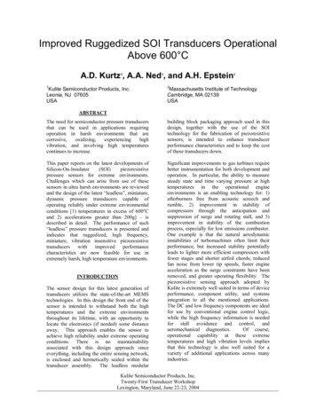
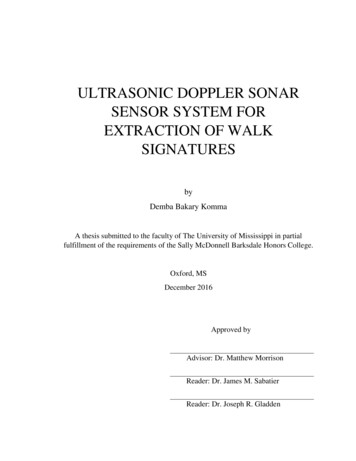
Transducer selection criteria—North American standardsFor transducers manufactured to North American standards,Baker Hughes Inspection Technologies offers threeperformance ranges: Alpha, Benchmark, and Gamma Series.Waveform and frequency certification, per ASTM E-1065, aresupplied with all flaw detection transducers at no charge.Alpha series features100.0m Volts/divReal time2 dB/divSpectrum1.25MHz/div200.0ns/divGamma series features Recommended for applications where resolution is theprimary consideration. Suitable for applications such as thickness measurementand near-surface flaw detection. Very short pulse—mechanically damped to the limit ofcurrent technology. Gain is usually lower than that of the Gamma andBenchmark Series. Broadband—typical 6 dB bandwidths range from 50%to 100%. Typical Alpha waveforms (right) exhibit one to two full ringcycles, depending on frequency, size and other parameters.Benchmark series features100.0m Volts/divReal time Proprietary BENCHMARK COMPOSITE (piezocomposite)active elements. Penetration in attenuative materials is far superior toconventional transducers. High signal to noise on coarse grain metals, fiberreinforced composites, et al. Short pulse—resolution usually superior to Gamma Series. Gain is usually higher than that of the Gamma andAlpha Series. Very broadband—typical 6 dB bandwidths range from60% to 120%. Low acoustic impedance element improves performanceof angle beam, delay line, and immersion probes—excellent match to plastic and water.2 dB/divSpectrum1.25MHz/div100.0m Volts/divReal time2 dB/divSpectrum1.25MHz/div200.0ns/div General purpose transducers, recommended for themajority of applications. Medium pulse, medium damping—best combination ofgain and resolution. Matching electrical network ensures maximum gain andoptimum waveform for general use. Medium bandwidth—typical 6 dB bandwidths range from30% to 50%. Typical Gamma waveform exhibits three to four full ringcycles, depending on frequency, size and other parameters.200.0ns/div7
Contact transducersStraight beam contacttransducers, protective faceApplications General purpose, larger parts with simple geometryForgings, billetsPlates, bars, square profilesContainers, machine components, shellsInspection at high temperature with delay lineFeatures and benefits European models have replaceable membrane:– Improves coupling on uneven or curved surface– Extends transducer life.– Suitable for DGS flaw sizing method– High temperature delay lines also available– Lemo 1 (B.S) or Lemo 00 (MB.S) connector, side mount standard, top mount optional North American models can be used with three types of protective face:– Membrane improves coupling on uneven or curved surface.– Wear cap extends transducer life indefinitely when replaced periodically.– High temperature delay line enables testing on surfaces up to 400 F (200 C).– BNC connector, side or top mount8
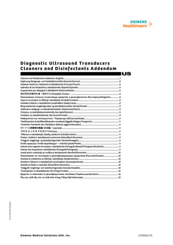
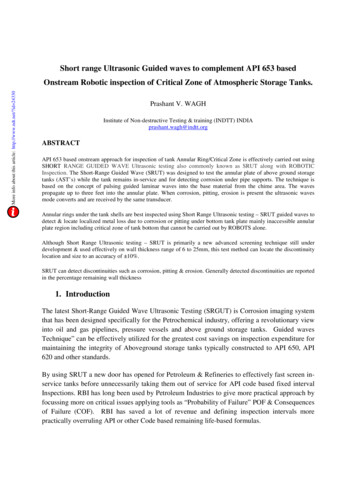
Protective face transducers—European standardsTypes B.S and MB.SMB.SB.SB2S2dB/DivAspectrumpulse shape50mV/DivB0,5µS/Div0 - 4MHzCasetypeABCmminmminmminType 2301.18592.32451.69Type 3200.79431.77250.98CTypical waveform and frequency 44240.941230.9B 1 S-EN0500035240.941230.9DIN EN 12668-2 compliantB 1 S-O0057755240.941230.9Top connectorB2S0057745240.942451.8B 2 S-EN0500036240.942451.8DIN EN 12668-2 compliantB 2 S-O0057756240.942451.8Top connectorB 2 S-O-EN0500267240.942451.8DIN EN 12668-2 compliant,top connectorB4S0057746240.944883.5B 4 S-EN0500037240.944883.5DIN EN 12668-2 compliantB 4 S-O0057757240.944883.5Top connectorB 4 S-O-EN0500268240.944883.5DIN EN 12668-2 compliant,top connectorB5S0057747240.9451104.3MB 2 S0057748100.39280.3MB 2 S-EN0500038100.39280.3DIN EN 12668-2 compliantMB 2 S-O0057975100.39280.3Top connectorMB 4 S0057749100.394160.6MB 4 S-EN0500039100.394160.6DIN EN 12668-2 compliantMB 4 S-O0057976100.394160.6Top connectorMB 5 S0057750100.395200.8MB 5 S-O0057977100.395200.8Top connectorSketchType 2Type 3Custom configurationsare available byspecial order.For explanations tothe table data, referto s
Calibration blocks Transducer kits 44 Transducer certification 45 Tables and formulas. 5 Transducer selection criteria and performance General information The ultrasonic transducers in this catalog are divided into two general categories, Contact and Immersion. Transducers for the immersion method Immersion transducers Acoustically matched for best efficiency in water Suitable for .