Transcription
Application NoteAN000370CCS811Baseline Save and Restore on CCS811v2-00 2018-Aug-01
Document FeedbackCCS811Content GuideContent Guide1Introduction. 36Summary of Issues to Avoid . 92CCS811 Baseline Save andRestore . 47Revision Information . 108Legal Information . 113Polluted Air Start Up . 54When to Read the Baseline . 75When to Restore the Baseline . 8Application Note PUBLICAN000370 v2-00 2018-Aug-0111 2
Document Feedback1CCS811IntroductionIntroductionThis application note describes the baseline “save and restore” implementation supported in theCCS811 application firmware. The baseline “save and restore” feature enables the sensors to indicatethe air quality of the ambient conditions as soon as possible from powering on the sensor regardlessof those conditions. The feature needs to be implemented using a particular sequence and timing tobe effective.Application Note PUBLICAN000370 v2-00 2018-Aug-0111 3
Document Feedback2CCS811CCS811 Baseline Save and RestoreCCS811 Baseline Save and RestoreThe register address for the save and restore functionality is address 0x11, BASELINE. The hostshould read 2 bytes from this register to obtain the current baseline, or write 2 bytes to this address torestore a previously saved baseline.The baseline value is not simply the raw resistance value of the sensor in clean air, it also includessome additional factors used by the internal algorithms. It is not in a human readable format andshould never be modified. The byte order and content must be preserved.The save and restore flow diagram is shown below in Figure 1.Figure 1:Baseline Save and Restore I2C Transaction FlowHost ApplicationCCS811Start Mode(1)Results(2)Start ModeWait for resistance to stabilizeBaseline(3)Start Mode(1)Results(2)Store BaselineOFF PeriodStart ModeWait for resistance to stabilizeBaseline(3)Results(4)Write BaselineImproved accuracyThe baseline is read from the CCS811’s BASELINE mailbox and saved in memory, typically nonvolatile, on the host’s system. A saved baseline can then be written back to the CCS811 to allow thesensor to indicate the quality of air as soon as possible the next time the sensor is powered on.The baseline is relative to the ambient conditions experienced by the sensor from when it is enabled.No data from a previous run time is preserved in the CCS811, so the baseline must be saved beforepowering off the sensor. For the baseline to be representative of good air quality conditions theCCS811 needs to be exposed to clean air.Application Note PUBLICAN000370 v2-00 2018-Aug-0111 4
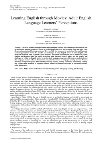
Document Feedback3CCS811Polluted Air Start UpPolluted Air Start UpThe CCS811 calculates the eCO2 and eTVOC using the baseline as its reference point. It comparesthe sensors current resistance with the baseline and if the current resistance is less than the baselinethen the sensor will indicate the presence of gas. If the current resistance is greater than or equal tothe baseline, then the current resistance becomes the new baseline. This is a simplified description,the algorithm is more complex and takes into account ambient temperature and humidity conditionswhen managing its baseline.Figure 2 below details the main reason why restoring a previously saved baseline is important forapplications that need to indicate air quality as soon as the sensor has warmed up.Figure 2:Baseline Save and Restore TimingSensor Resistance ,000150,000Clean Air Start-up100,000Clean Air Baseline(1) (1)50,000Polluted Air Start-up001530456075Time (minutes)The blue line shows that the sensor has stabilized at 350kΩ in clean air. The baseline in thisenvironment and at this point in the sensor’s lifetime is therefore 350kΩ (blue dotted line). Saving thebaseline at any time after point 3 will yield a value corresponding to 350kΩ. Let’s assume the sensor isswitched off and then 1 day later is powered on again in dirtier air. This time the sensor stabilizes at300kΩ as the air is now more polluted, this is shown in the red line.If no baseline is restored, the CCS811 will assume that a value of 300kΩ represents clean air and willuse this as its baseline. It does not retain baseline information from the last time it was powered on. Ituses the highest resistance value encountered over a window of time (default 24 hours) as itsbaseline.Application Note PUBLICAN000370 v2-00 2018-Aug-0111 5
Document FeedbackCCS811Polluted Air Start UpThe resistances and sensor output at each point is described below:1.The sensor is switched on and the baseline is quite close for the polluted air and clean air. Inthis early phase the sensor will give similar outputs in each start up condition. The baselinemust not be written in this period as the baseline resistance will much greater than the sensor’scurrent resistance. This would cause the sensor to falsely indicate very high VOCsconcentrations as it’s not yet fully warmed up.2.The conditioning period completes, the resistance in each case shows a visible difference. If nobaseline is restored at this point the sensor will give similar outputs in both cases. If thebaseline, saved from the clean air start up, is restored then the sensor will indicate that VOCsare present. There will be a larger output on eCO2/eTVOC after the baseline corresponding to350kΩ is restored. The sensor will now calculate a eTVOC concentration that is relative to thebaseline (350kΩ) and the sensor’s current resistance (approx. 300kΩ)3.If no baseline has been restored both environments will yield very similar outputs on the sensor.If the clean air baseline of 350kΩ is restored then this becomes immediately the baseline usedby the sensor and the sensor will detect the presence of VOCs in the polluted environment.4.Same as 3 above. The clean air baseline is the red line, if its corresponding value has not beenwritten at points 2 or 3 the sensor will think the air is clean and its baseline will be 300kΩ. If thebaseline is written to the value corresponding to 350kΩ, it will now calculate a eTVOCconcentration that is relative to the baseline (350kΩ) and the sensor’s current resistance(approx. 300kΩ).Application Note PUBLICAN000370 v2-00 2018-Aug-0111 6
Document Feedback4CCS811When to Read the BaselineWhen to Read the Baseline The CCS811 constantly monitors and maintains its baseline. Reading the baseline at any timewill return the value that the sensor’s algorithms currently calculate to be the cleanest airencountered in a programmable window (default 24 hours). This value can be saved in nonvolatile memory on the host system ready to written at next power on.The baseline is safe to be read at any time after the conditioning period is complete, however itis recommended to read and save the baseline if the user knows the sensor has encounteredclean air at any point after the conditioning period. If this is not known it is best practice to readthe baseline directly before powering down the system.If an ad hoc power cut is possible it is also recommended to read and save the baselineperiodicallyDue to the slow drift that MOX sensors inherently exhibit, the saved baseline will not match thecurrent baseline if it has not been saved for many days. In the first week of operation sensor it is recommended to save a new baseline every 24hoursAfter 1 week of operation it can be saved every 1-28 daysIf multiple IAQ operating modes are used on the same sensor, the baseline should be stored foreach mode. The baseline is mode specific, it is therefore not possible to use the same baselinevalue for all modes.If multiple sensors are operating in the same environment and in the same mode each sensorwill maintain its own unique baseline. It is therefore not possible to use the same baseline for allof the sensors operating in the same mode.If the sensor is only run for short intervals (under 24 hours) the automatic baseline correctionperiod can be programmed to closely match the duration of the on time.Application Note PUBLICAN000370 v2-00 2018-Aug-0111 7
Document Feedback5CCS811When to Restore the BaselineWhen to Restore the Baseline The baseline should be restored after the conditioning period.The baseline takes into account the temperature and humidity data that is written to the sensor.If a sensor that has completed the conditioning period is exposed to an environment that ismuch different in temperature and humidity than its current environment then baseline restoringis recommended. In this case, restoring the most recently saved baseline after the sensorstabilizes ( 30 seconds) in the new environment will yield an accurate measurement in the newconditions.Application Note PUBLICAN000370 v2-00 2018-Aug-0111 8
Document Feedback6CCS811Summary of Issues to AvoidSummary of Issues to Avoid Do not use one baseline setting for all sensors. The baseline needs to be stored on a device bydevice basis.Do not use the first baseline you have read for the lifetime of the sensor. The baseline willchange during the lifetime of the sensor. Periodically re-read and save the sensor baseline e.g.every 7 daysDo not save or restore the baseline while the sensor is still in the process of warming up. Thebest user experience would be to allow the sensor to complete the conditioning period beforethe baseline is written to avoid falsely high eTVOC level indications in the first 20 minutes ofoperationDo not use the same baseline value for all operating modes field settings. Each mode has itsown baseline value which must be saved while operating in that mode.Application Note PUBLICAN000370 v2-00 2018-Aug-0111 9
Document Feedback7CCS811Revision InformationRevision Information Changes from previous version to current revision v2-00PageFixed TyposAllPage and figure numbers for the previous version may differ from page and figure numbers in the current revision.Correction of typographical errors is not explicitly mentioned.Application Note PUBLICAN000370 v2-00 2018-Aug-0111 10
Document Feedback8CCS811Legal InformationLegal InformationCopyrights & DisclaimerCopyright ams AG, Tobelbader Strasse 30, 8141 Premstaetten, Austria-Europe. Trademarks Registered. All rights reserved.The material herein may not be reproduced, adapted, merged, translated, stored, or used without the prior written consent of thecopyright owner.Information in this document is believed to be accurate and reliable. However, ams AG does not give any representations orwarranties, expressed or implied, as to the accuracy or completeness of such information and shall have no liability for theconsequences of use of such information.Applications that are described herein are for illustrative purposes only. ams AG makes no representation or warranty that suchapplications will be appropriate for the specified use without further testing or modification. ams AG takes no responsibility forthe design, operation and testing of the applications and end-products as well as assistance with the applications or end-productdesigns when using ams AG products. ams AG is not liable for the suitability and fit of ams AG products in applications andend-products planned.ams AG shall not be liable to recipient or any third party for any damages, including but not limited to personal injury, propertydamage, loss of profits, loss of use, interruption of business or indirect, special, incidental or consequential damages, of anykind, in connection with or arising out of the furnishing, performance or use of the technical data or applications describedherein. No obligation or liability to recipient or any third party shall arise or flow out of ams AG rendering of technical or otherservices.ams AG reserves the right to change information in this document at any time and without notice.RoHS Compliant & ams Green StatementRoHS Compliant: The term RoHS compliant means that ams AG products fully comply with current RoHS directives. Oursemiconductor products do not contain any chemicals for all 6 substance categories, including the requirement that lead notexceed 0.1% by weight in homogeneous materials. Where designed to be soldered at high temperatures, RoHS compliantproducts are suitable for use in specified lead-free processes.ams Green (RoHS compliant and no Sb/Br): ams Green defines that in addition to RoHS compliance, our products are free ofBromine (Br) and Antimony (Sb) based flame retardants (Br or Sb do not exceed 0.1% by weight in homogeneous material).Important Information: The information provided in this statement represents ams AG knowledge and belief as of the date thatit is provided. ams AG bases its knowledge and belief on information provided by third parties, and makes no representation orwarranty as to the accuracy of such information. Efforts are underway to better integrate information from third parties. ams AGhas taken and continues to take reasonable steps to provide representative and accurate information but may not haveconducted destructive testing or chemical analysis on incoming materials and chemicals. ams AG and ams AG suppliersconsider certain information to be proprietary, and thus CAS numbers and other limited information may not be available forrelease.HeadquartersPlease visit our website at www.ams.comams AGBuy our products or get free samples online at www.ams.com/ProductsTobelbader Strasse 30Technical Support is available at www.ams.com/Technical-Support8141 PremstaettenProvide feedback about this document at www.ams.com/Document-FeedbackAustria, EuropeFor sales offices, distributors and representatives go to www.ams.com/ContactTel: 43 (0) 3136 500 0For further information and requests, e-mail us at ams sales@ams.comApplication Note PUBLICAN000370 v2-00 2018-Aug-0111 11
baseline is restored at this point the sensor will give similar outputs in both cases. If the baseline, saved from the clean air start up, is restored then the sensor will indicate that VOCs are present. There will be a larger output on eCO2/eTVOC after the baseline corresponding to 350kΩ is restored.