Transcription
Improved Ruggedized SOI Transducers OperationalAbove 600 CA.D. Kurtz1, A.A. Ned1, and A.H. Epstein21Kulite Semiconductor Products, Inc.Leonia, NJ 07605USA2Massachusetts Institute of TechnologyCambridge, MA 02139USAABSTRACTThe need for semiconductor pressure transducersthat can be used in applications requiringoperation in harsh environments that arecorrosive,oxidizing,experiencinghighvibration, and involving high temperaturescontinues to increase.building block packaging approach used in thisdesign, together with the use of the SOItechnology for the fabrication of piezoresistivesensors, is intended to enhance transducerperformance characteristics and to keep the costof these transducers down.This paper reports on the latest developments ofSilicon-On-Insulator(SOI)piezoresistivepressure sensors for extreme environments.Challenges which can arise from use of thesesensors in ultra harsh environments are reviewedand the design of the latest “leadless”, miniature,dynamic pressure transducers capable ofoperating reliably under extreme environmentalconditions [1) temperatures in excess of 600 Cand 2) accelerations greater than 200g] – isdescribed in detail. The performance of such“leadless” pressure transducers is presented andindicates that ruggedized, high frequency,miniature, vibration insensitive aracteristics are now feasible for use inextremely harsh, high temperature environments.Significant improvements to gas turbines requirebetter instrumentation for both development andoperation. In particular, the ability to measuresteady state and time varying pressure at hightemperatures in the operational engineenvironments is an enabling technology for: 1)afterburners free from acoustic screech andrumble, 2) improvement in stability ofcompressors through the anticipation andsuppression of surge and rotating stall, and 3)improvement in stability of the combustionprocess, especially for low emissions combustor.One example is that the natural aerodynamicinstabilities of turbomachines often limit theirperformance, but increased stability potentiallyleads to lighter more efficient compressors withfewer stages and shorter airfoil chords, reducedfan noise from lower tip speeds, faster engineacceleration as the surge constraints have beenremoved, and greater operating flexibility. Thepiezoresistive sensing approach adopted byKulite is extremely well suited in terms of deviceperformance, component utility, and systemsintegration to all the mentioned applications.The DC and low frequency components are idealfor use by conventional engine control logic,while the high frequency information is neededfor stall avoidance and control, andaeromechanical diagnostics.Of course,operational capability at these extremetemperatures and high vibration levels impliesthat this technology is also well suited for avariety of additional applications across manyindustries.INTRODUCTIONThe sensor design for this latest generation oftransducers utilizes the state-of-the-art MEMStechnologies. In this design the front end of thesensor is intended to withstand both the hightemperatures and the extreme environmentsthroughout its lifetime, with an opportunity tolocate the electronics (if needed) some distanceaway. This approach enables the sensor toachieve high reliability under extreme operatingconditions. There is no maintainabilityassociated with this design approach sinceeverything, including the entire sensing network,is enclosed and hermetically sealed within thetransducer assembly. The leadless modularKulite Semiconductor Products, Inc.Twenty-First Transducer WorkshopLexington, Maryland, June 22-23, 2004
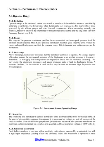
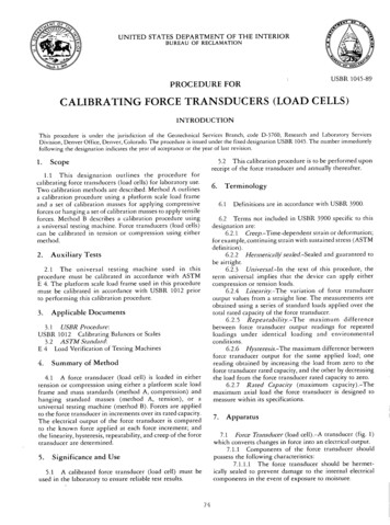
Figure 1Piezoresistive transducers pursued herein aresuperior to alternative approaches for severalreasons. First, unlike piezoelectric transducers,fragile controlled impedance wiring and bulkyand expensive charge amplifiers are not required.Also, unlike the piezoelectric devices, which canonly be used for dynamic measurements, thepiezoresistive devices can be used for both staticand dynamic measurements. Furthermore, theentire piezoresistive transducer and its leads aredesigned for the real engine, 600 C (1100 F)environment, while only the face of apiezoelectric sensor can be exposed (the rest ofthe transducer and its leads must be cooled).While fiberoptic devices do not yet exist forflight engine environments, the ones proposedrequire relatively bulk, power consumingelectro-optics which must be provided with acool, benign environment. In many applicationssuch an environment is considered very dearreal-estate. Thus, the new technology describedherein offers the system level advantages ofcomplete freedom from transducer cooling andthus more freedom for transducer placement,multifunction transducers, reduced transducerelectronics, and reduced fuel control housingvolume. Overall, this improves the cost, weight,and reliability penalties associated with theadditional control functionality desired foradvanced engine concepts.THE SILICON-ON-INSULATOR(SOI) SENSORFor the last 40 years, Kulite has supplied highperformance pressure transducers to theaerospace industries for both research anddevelopment and for production applications.These transducers are based upon thepiezoresistive silicon technology, which Kulitepioneered [1] and developed to its current highlevels of performance and reliability. The latestevolution of sensors at Kulite, including theleadless sensor, uses silicon on insulator (SOI)technology [2,3].Piezoresistive silicon strain gauges are integratedwithin the silicon diaphragm structure but areelectrically isolated from the silicon diaphragmas shown schematically in Fig. 1.The piezoresistors measure the stress in thesilicon diaphragm, which deflects as a directfunction of the applied pressure.There are two core elements of the currentgeneration of devices which will be consideredin turn: the production of a suitable deflectingdiaphragm to convert applied pressure intodisplacement, and the addition of piezoresistivestrain gauge elements to the diaphragm to recordthe displacement.The latest evolution of the patented Silicon onInsulator (SOI) technology enables theKulite Semiconductor Products, Inc.Twenty-First Transducer WorkshopLexington, Maryland, June 22-23, 20042
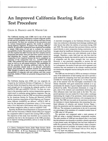
Figure 2piezoresistivesensing elementstobedielectrically isolated from, while beingmolecularly attached to a silicon diaphragm (Fig.2).The process for fabricating the compositedielectrically isolated SOI sensor structurerequires the use of two separate wafers. The first“Pattern” wafer is specifically selected ics of the sensor chip, while thesecond “Substrate” wafer is specifically selectedto optimize the capabilities of micromachiningthe sensing diaphragm. A layer of high qualitythermally grown oxide is then grown on thesurface of the substrate, while the piezoresistivepatterns are introduced into the pattern wafer.The piezoresistive patterns are diffused to thehighest concentration level (solid solubility) inorder to achieve the most stable, long-termelectrical performance characteristics of thesensing network. Once the pattern and thesubstrate wafers are appropriately processed, theFigure 3two wafers are fusion bonded together using aspecifically developed and patented diffusionenhanced fusion bonding technique [2]. Theresulting molecular bond between the two wafersis as strong as silicon itself, and since both thesensing elements and the diaphragm arecomprised of the same Si material, there is nothermal mismatch between the two, thusresulting in very stable-accurate performancecharacteristics with temperature. The presenceof dielectric isolation enables the sensor tofunction at very high temperatures without anycurrent leakage effects associated with the p-njunction type devices. Since the device iscapable of operating at high temperatures, a hightemperature metallization scheme is introducedto enable the device to interface with the headerat these high temperatures as well.The micromachining is performed using acombination of different wet (Isotropic andAnisotropic) chemical etch processes. The shapeand performance characteristics of themicromachined sensing diaphragm are modeledusing finite element analysis at the initial designstage. The composite silicon sensor is attached toa Pyrex pedestal, by an anodic bonding process,to form a pressure-sensing capsule as shown inFig 3.The pedestal material is selected to thermallymatch the physical characteristics of the siliconsensor.The sensing circuit is electrically isolated fromthe metallic housing by virtue of the nonconductive pedestal in the pressure capsule. Theisolation resistance and the dielectric strength areinherently very high. The reference pressure isKulite Semiconductor Products, Inc.Twenty-First Transducer WorkshopLexington, Maryland, June 22-23, 20043
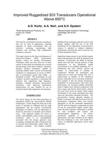
obtained from the cavity between the diaphragmand pedestal, which has a true hermetic seal.LEADLESS SENSOR DESIGNIn the semiconductor sensor industry, thestandard method of providing electricalconnections between sensor chip and package iswirebonding. The ultrasonic agitation used toform the wirebonds causes abrasion to take placeduring the welding process and allowsmicroscopic holes to develop in themetallization through which, at high operationtemperatures, the gold can migrate and form agold-silicon eutectic which causes the leads tofail. In addition, the pressure media is in directcontact with the stress-sensing network, leadoutsand interconnects, which can fail at hightemperatures and in the presence of aggressivechemicals. The key elements in the design of aruggedized pressure sensor is the elimination ofgold bond wires and the protection of sensingelements from corrosive environments at hightemperatures, hence the reference to the newsensor capsule as the leadless design [4,5,6].The leadless sensor uses high temperaturemetal-glass mixtures for providing electricalconnections between sensor chip and package.The leadless sensor capsule is comprised of twomain components, the sensor chip and the coverwafer, which are eventually assembled to formthe pressure capsule.separations between the contact regions of thebridge. Metal is deposited to form ohmiccontacts to the P regions located inside thelarge contact regions. There is also a rim of P material around the periphery of the sensor chip.When the cover wafer is assembled to the sensorchip, an hermetic seal is formed between thecover and this rim area of P material, thusprotecting the stress sensing network and all theelectrical interconnections from the harshenvironmental conditions. The cover wafer ismanufactured from a Pyrex glass to the samedimensions as the silicon wafer. Four holes aremicromachined in the cover, one in each corner,which align with the metallized contact padareas. A cavity is also created in the center ofthe cover wafer to allow the diaphragm to deflectfreely when assembled. The sensor chip and thecover wafer are then assembled using anodicbonding.Fig. 5 shows a top isometric view of thecomponents just prior to sealing. Once the twowafers are bonded, only the metallized leadoutpads are effectively exposed, while all thegauges and electrical interconnections on thesensing side of the silicon chip are sealed by thecover. Thus, the active portion of the pressuresensor is hermetically isolated.Figure 5Fig. 4 shows a photograph of the sensor chipwith the four-piezoresistive gauges strategicallypositioned inside the sensing diaphragm regionand connected in a Wheatstone bridge. Theentire sensing network is P Si and there areFigure 4Leadless (SOI) Sensor with Cover GlassAttachedSENSOR IMPROVEMENTKulite is continuing to develop and optimize thesensor chip design and the associated packagingtechniques.The latest generation of theoptimized sensors includes: a) improvement ofthe overall performance characteristics of thesensor through finite element analysis andmodeling, and b) increase of the temperatureKulite Semiconductor Products, Inc.Twenty-First Transducer WorkshopLexington, Maryland, June 22-23, 20044
Figure 6SIDE VIEW OF THE “LEADLESS CHIP COMPOSITE” AFTERFILLING WITH GLASS-METAL PASTE FOR CONTACTINGcapability of the leadless sensor.a) Finite Element Analysis modeling wasperformed to better understand the presentdesigns and to fine-tune the new designs. Thenew designs were established to improveperformance such as enabling larger, morelinear, and more stable output characteristics fora specific sensor diaphragm thickness.Increasing the sensors output also created anopportunity to increase the diaphragm thicknessfor the respective design (in obtaining the sameoutputs), thus leading to further improvements inthe overall stability and repeatability of thesensors.b) A significant effort is underway at Kulite toimprove the metallization scheme on the sensingchip in order to enable device operation at ultrahigh temperatures. New metallurgical systemshave demonstrated the capability of themetalized contacts on the sensing chips towithstand exposure to temperatures up to 650 C(1200 F) for many hours.dielectric breakdown occurrencetemperatures well above 700 C.uptoTHE LEADLESS PACKAGINGTo avoid the use of gold ball bonds and fine goldwires, a high temperature metal frit is used toprovide the electrical connection between thesensing chip and a specially designed header.The frit is a mixture of high conductivity metalpowders in appropriate physical form and glass,and is used to fill the holes in the cover waferafter it is attached to the sensor chip (Fig. 6).The specially designed header contains a groupof four hermetically sealed pins protruding fromits surface, which are spaced so as to fit the holesdrilled in the cover wafer. The leadless sensor isbonded to the header at a high temperature usinga non-conductive glass frit, and during thisprocess the metal frit in the cover wafer holesmelts and creates lo
Kulite Semiconductor Products, Inc. Twenty-First Transducer Workshop Lexington, Maryland, June 22-23, 2004 Improved Ruggedized SOI Transducers Operational Above 600 C A.D. Kurtz1, A.A. Ned1, and A.H. Epstein 2 1Kulite Semiconductor Products, Inc. 2Massachusetts Institute of Technology Leonia, NJ 07605 Cambridge, MA 02139 USA USA ABSTRACT The need for semiconductor pressure transducers