Transcription
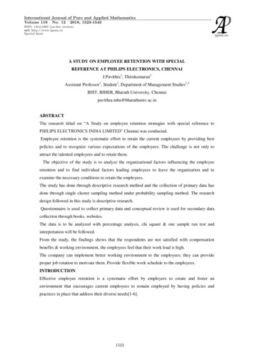
ElectromagneticSolutionsMagnet Retention inPermanent Magnet DCMotors – Part IIntroduction and OverviewFor more than 50 years, Windings has provided engineered electromagnetic solutions for criticalapplications in Aerospace, Defense, Automotive and Oil & Gas industries. As a full-service provider,Windings is a leader in the design, test, manufacture and support of custom electric motors, generators andrelated components including rotors, stators, lamination stacks and insulation systems.
From Induction to PermanentMagnetsFor decades, alternating current induction motors(ACIM) have provided the driving force forcommercial and industrial applications. Theseasynchronous motors feature simple and robustdesigns, require little maintenance, functionreliably in a range of uses, require very simpleelectric starters/contactors to operate, and areinexpensive to manufacture. Asynchronous rotorsare cast; the magnetic field necessary to oppose theelectromagnetic field generated in the stator windingis induced in the rotor. No permanent magnets areused. But ACIM have limitations: Single phase ACIMhave low starting torque, are relatively inefficientunder lighter loads, and are acceleration-limited dueto inherently high rotor inertia.As demand increased for higher motor acceleration,power density, and overall efficiency, motormanufacturers have turned to synchronous motordesigns. Permanent magnet synchronous motors(PMSM) incorporate permanent magnets to supplythe necessary opposing magnetic field. Thissignificantly increases torque density and efficiency,particularly during acceleration, by eliminating theextra current required to induce the magnetic field.Initially, PMSMs were configured with permanentmagnets adhered to the inside of the motor housingand electromagnetic windings fixed to the rotor.This configuration, commonly referred to as abrushed DC motor, uses carbon brushes and acopper commutator to feed electrical current tothe rotor windings. Brushed DC motors sharethe ACIM benefits of simple and robust designs,simple electric starters/contactors for operation,and low manufacturing costs. They also share thedrawback of limited acceleration due to high rotorinertia and have higher maintenance requirementsdue to constant wear on the carbon brushes duringoperation.Continuing customer demand for higheracceleration, as well as for point-to-point positioningand more accurate position control, spawned thedevelopment of brushless DC (BLDC) motors. Aninversion of the brushed DC configuration, BLDC2motors feature permanent magnets mounted tothe rotor and electromagnetic windings fixed to theinside of the motor housing. Locating the permanentmagnets on the rotor significantly reduces rotorinertia, enabling higher acceleration. The downsideto this approach is the need for a rotor positionfeedback device and complex external electronicsto track rotor position and manipulate current inthe stator windings to produce the desired motionoutput. Higher performance came with higheroverall system cost and complexity, and concernover magnet retention—especially at high rotationalspeeds.Properties of Magnetic MaterialsPermanent magnet material selection significantlyaffects the overall performance of a BLDC motor;it is one of the most critical decisions an engineermakes during the design process. Magnetite,a naturally occurring iron ore, has the highestmagnetism of any mineral, but has limited magneticstrength. Ceramic ferrites—alloys of iron oxidewith barium, manganese, nickel, or zinc—can bemagnetized; and aluminum, nickel, and cobalt(alnico) alloys have even stronger magneticproperties.In the 1960s, scientists at the US Air ForceMaterials Laboratory alloyed yttrium and cobaltto create the first rare earth magnets, strongerthan even alnico. Further research resulted incombinations of neodymium and samarium–cobalt.These component minerals are called rare earthnot because they are scarce, but because they arediffuse and difficult to mine in quantity.In addition to cost, rare earth magnets have twoserious drawbacks: They are brittle and vulnerableto corrosion. To reduce the risk of damage ordisintegration, these magnets are often platedor coated with more durable materials such asnickel-copper-nickel. Also, at extremely hightemperatures, even rare earth magnets can becomedemagnetized.Despite these limitations, rare earth magnets arethe key to high power density and efficiency inelectric motors. No other material helps generate
as much output with the same energy inputs. Soholding those magnets in place becomes a criticalconsideration for design engineers. To optimizeperformance, the designer must keep the magnetsas close as possible to the stator windings;minimizing the air gap between the rotor and statorwill maximize torque. The drawback is that as the airgap decreases, manufacturing difficulty increases ina non-linear fashion.Surface and Interior MountingStricter government standards for electric motorefficiency have put tremendous pressure on ACIMmanufacturers. Initial efforts to increase efficiencywere focused on magnet wire material and rotordesigns, followed by the use of external variablefrequency drive electronics to control accelerationand minimize inrush current during startup. Morerecently, ACIM designers have incorporatedpermanent magnets in rotor designs to furtherboost electrical efficiency. These modern ACIMconfigurations embed the permanent magnets intoa stack of magnetic steel laminations bonded tothe rotor. This configuration is called an interiorpermanent magnet rotor. Because the magnets arecaptured within the rotor lamination stack, there islittle concern over magnet retention.Unlike the ACIM configuration, permanent magnetsin a BLDC motor are bonded to the outside of therotor, a configuration called a surface permanentmagnet rotor. Surface mounted magnets need tobe held in place with a very strong and reliableadhesive to prevent movement or breakage of themagnets during operation, complicating designrequirements and adding to manufacturing costs—but surface magnet rotors offer higher performancecharacteristics than interior magnet rotors.Evolution of DesignIn the publication IEEE Transactions on IndustryApplications in 1996, authors Michael W. Degner,Richard Van Maaren, Azza Fahim, Donald W.Novotny, Robert D. Lorenz, and Charles D.Syverson outlined the problems of magnet retentionon high speed rotors:“The advent of high-energy product, rare-earthpermanent magnet materials has broughtabout a resurgence in the use of permanentmagnets to provide the field excitation forelectric machines. The rare-earth permanentmagnet materials allow machines of very highefficiency and energy densities to be built.The use of permanent magnets to provide thefield excitation in an AC generator reducesthe size and complexity of the generator. Theslip rings and field excitation no longer haveto be provided, and the high energy density ofthe permanent magnets allows the size andweight of the alternator to be reduced. Oneof the most important issues in the designand manufacturing of any permanent magnetmachine is the method used to hold the magnetsin place and to prevent them from flying offduring operation due to centrifugal forces.”The authors clearly describe the options designengineers had at the time:“Gluing or banding the magnets in placeincreases the cost and complexity of themanufacturing process, whereas, burying themagnets increases the magnet leakage fluxand the complexity of the magnetic design andmodel.”At higher performance levels, adhesive alone wasnot enough to retain the position and integrity ofsurface mounted magnets for the expected life ofthe motor. Motor designers gradually took a “beltand suspenders” approach to magnet retentionand started wrapping the rotor assemblies, knownas “roving,” with various materials to securethe magnets in place should the glue bond fail.Common materials used for banding or rovingincluded fiberglass, Kevlar, and Inconel. Thesematerials provided added protection and in manycases extended the life of the motor, but they werestill vulnerable to failure in demanding applicationsinvolving high speeds or high temperatures. Theauthors went on to recommend the latter method, aburied magnet design:“A major problem in the design andmanufacturing of surface mounted permanentmagnet machines is reliably holding thepermanent magnets in place at high speeds.3
This paper evaluates a unique rotor laminationdesign for a high pole number, permanentmagnet alternator. This buried magnet design,which is capable of reliably holding thepermanent magnets in place at high speeds,offers both easier and cheaper assembly whencompared with the methods currently used insurface mounted permanent magnet machines.Finite element analysis is used to comparethe buried magnet design with equivalentsurface mounted designs and shows that theperformance of the alternator is not significantlyaffected by the iron over the magnets.”Finally, the authors suggest possible designimprovements to reduce lamination complexity:“Another possibility is the use of a solid‘can’ made of either magnetic or nonmagneticmaterial to surround the surface mountedmagnets and hold them in place. A magnetic‘can’ of course increases the potential forleakage flux and core losses due to its highpermeability and low resistance, but it is cheaperand mechanically stronger than many of thenonmagnetic options. To prevent the magnetsfrom becoming loose at high speed the ‘can’or banding have to be pre-loaded when put inplace. The pre-loading can be achieved by theuse of thermal expansion and cooling in thecase of a ‘can,’ or the stretching of the bandingas it is applied over the permanent magnets.”This recommendation pointed the way for much ofthe development that has happened since. Hereis a brief description of some of these retentionmethods:Magnet Retention SlotsIn 2001 and 2002, inventors John Weiglhofer,Stewart Peil, and Pieter Van Dine of the ElectricBoat Corporation filed patent applications fortwo methods of retaining permanent magnetsin high speed rotors. Both used channels in therotor surface to keep the magnets in place. Thefirst, U.S. Patent 6492754, was titled “Magnetretention channel arrangement for high speedoperation.” The second, U.S. Patent 6548932,4was titled “Nonmagnetic magnet retention channelarrangement for high speed rotors.” Apart fromthe difference in magnetic properties of thechannel material, the two designs had very similardescriptions.In 2008, Hamilton Sundstrand (now part of CollinsAerospace) filed a patent for retention of permanentmagnets in rotors. Titled “Magnet retention systemfor permanent magnet motors and generators,” itdescribed a design with slots in the rotor that heldthe flanged lower edges of permanent magnets.Each retention slot had a base that extendedaxially into the rotor flange, a pair of side walls thatextended from the base, and a pair of lugs thatprojected from the side wall to hold the magnet bothradially and tangentially. A spring pre-loaded axialretention ring also helped keep each magnet inplace.Magnet Retention WedgesIn 2015, inventors Petri J. Maki-Ontto, FredrikBoxberg, and Esa H. Vikman, representing theIngersoll-Rand Company, filed a patent applicationfor a design that uses wedges to hold permanentmagnets in place. The function is similar to that ofthe channels and slots listed above. Titled “FixationSystem for a Permanent Magnet Rotor,” the designwas described as follows:“A fixation system that is structured to secureone or more permanent magnets to a rotor core.The fixation system may include one or moreretention wedges that exert an interferenceor press fit against the permanent magnets tosecure the permanent magnets to the rotor core.At least a portion of the retention wedges maybe secured within axially extending channelsin the rotor core. Additionally, the permanentmagnets may be separated from each otherby eddy current shields, which may also beretained in position by the retention wedges.The fixation system may also include a magnetpressure or fixation sleeve that exerts a radiallyinwardly directed force against the magnetsand is free from direct contact with the retentionwedges.”
Magnet Retention SleevesEngineers were already experimenting withencapsulating sleeves when Degner et al madetheir recommendation. Manufacturers have triedwrapping permanent magnet rotors in materials thatrange from nonmagnetic alloys to carbon fiber, withvarying degrees of complexity and cost.Robert Cole, representing the A.O. SmithCorporation, was granted U.S. Patent 4,855,630with the title “Permanent Magnet Rotor with MagnetRetention Band” in 1989. He described the design,in part, as follows:“A rotor structure for a dynamoelectric machineincluding a magnetic core having a cylindricalouter surface. Equicircumferentially spacedpermanent magnets are secured to theface of the core with gaps therebetween ondiametrically opposite locations of the core.The outer surfaces of the magnets define acylindrical surface. A retention band encirclesthe magnets. The band has a width substantiallyless than the width of the magnets includingopposite ends overlapped and aligned with asecurement gap.”This is similar to more recent sleeve designs; themost significant difference has been the materialschosen with each iteration. In 2019, Co Huynh ofCalnetix Technologies described the current state ofmaterial options this way:“There are two primary technologies of magnetretention in high speed permanent magnetmachines, namely high-strength non-magneticmetal sleeve and a proprietary advancedgraphite-composite sleeve. Each offers uniqueadvantages to the system and motor/generatorperformance. The metal sleeve can be designedto provide some stiffness to the rotor structure.It also acts to effectively shield the magnetsfrom stator’s harmonic currents. Eddy currentsgenerated in the metal sleeve due to [the]stator’s harmonic currents and stator slottingimpede high frequency fields from penetratingthe magnets and generate losses. Most of theabsorbed energy in the metal sleeve readilydissipates to the cooling medium in the airgapand the rest is conducted to the magnets and/or end supports. Carbon fiber sleeves aresignificantly stronger and lower density thantheir metal counterparts thus allow the useof more magnet mass or thinner sleeve forsimilar magnet volume. The result is smallermagnetic gap and better magnetic performancewith carbon fiber sleeve. However, they do notprovide any harmonic filtering. Moreover, due totheir low thermal conductivity they act as thermalbarriers to heat generated in the magnets. Rotorloss reduction and management techniquessuch as segmenting magnets or conductivelayer shielding can be employed to enhancesystem performance when using carbon fibersleeves.”SummaryIn the time between Robert Cole’s patent andthe state of the industry described by Co Huynh,permanent magnet motors have become ubiquitousin advanced machines. As engineers designequipment for demanding environments, theyvalue the high torque, high efficiency, and lowmaintenance requirements of permanent magnetmotors. Magnet retention remains a challenge,particularly as performance demands continue toescalate.For now, leading manufacturers will offer metallicsleeves in materials such as 300 CRES stainlesssteel, A286 iron-nickel-chromium alloy, and Inconelsuperalloys—and in thermoplastic, thermoset,and high-strength carbon fiber, according to therequirements of each machine design.For further information, please contact dings.com 2019 Windings, Inc. All brand and product names are trademarksor registered trademarks of their respective owners. Information in thisdocument is believed accurate at time of printing. However, Windingsassumes no responsibility for its use or for any errors that may appearin this document. Information in this document is subject to changewithout notice. (10/2019)5
magnets adhered to the inside of the motor housing . combinations of neodymium and samarium–cobalt. These component minerals are called rare earth . “Gluing or banding the magnets in place increases the cost and complexity of