Transcription
Freescale Semiconductor, Inc.Application NoteDocument Number: AN5070Rev. 0, 07/2015Implementing Data Whitening andCRC Verification in Software inKinetis KW01 Microcontrollers1IntroductionWhen establishing communication with third party productsthere are cases when the data whitening and CRC algorithmsavailable in hardware are not compatible between devices.To overcome this limitation, this application note provides asoftware-based implementation.The use case presented, contains a Packet Error Rate (PER)application using the Kinetis KW01 microcontrollers, whereIBM data whitening and CRC calculations are implementedin software to comply with the hardware algorithms of thirdparty products.2AbstractThis application note describes a use case in which theKW01 microcontroller interacts with another KW01 MCU(emulating a third party device such as TI’s CC1110) byimplementing data whitening and CRC computations insoftware.Tools required to run this application are the IAR EmbeddedWorkbench for ARM v7.10 (or newer) and the FreescaleTower System using the TWR-RF development board. 2015 Freescale Semiconductor, Inc. All rights ion . . . . . . . . . . . . . . . . . . . . . . . . . . . . . . . . . . 1Abstract . . . . . . . . . . . . . . . . . . . . . . . . . . . . . . . . . . . . . . 1Principle of data whitening . . . . . . . . . . . . . . . . . . . . . . . 2Hardware implementation in KW01 MCUs . . . . . . . . . . 2Hardware implementation for application . . . . . . . . . . . 4Software implementation application pre-configuration 10Application procedure . . . . . . . . . . . . . . . . . . . . . . . . . 13Summary of software implementation . . . . . . . . . . . . . 19Conclusions . . . . . . . . . . . . . . . . . . . . . . . . . . . . . . . . . 19References . . . . . . . . . . . . . . . . . . . . . . . . . . . . . . . . . . 19Revision history . . . . . . . . . . . . . . . . . . . . . . . . . . . . . . 19
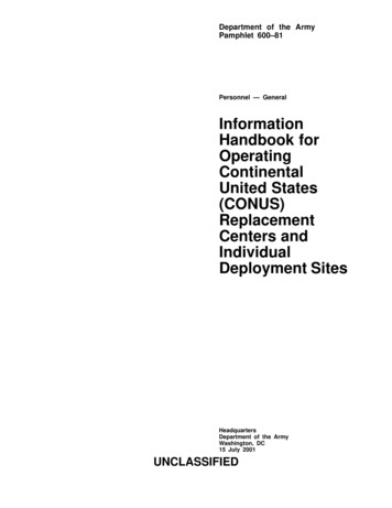
Principle of data whitening3Principle of data whiteningIn an RF system, transmitted data is grouped into packets. These packets may contain long sequences of0's and 1's which can introduce a DC bias into the transmitted signal. A radio signal with a DC bias willhave a non-uniform power distribution over the occupied channel bandwidth. A DC bias will alsointroduce data dependencies during normal operation of the demodulator. However, it is optimal for thetransmitted data to be random and DC free.As will be discussed, CCITT data whitening processes the data packets byte-per-byte, whereas IBM datawhitening processes the data packets bit-per-bit. The data is whitened using a random sequence duringtransmit and de-whitened during receive using the same sequence.NOTETwo techniques are available in the packet handler: Manchester encodingand data whitening, however, for the purpose of this application note we willfocus only in the data whitening implementation available in the KinetisKW01 devices. Only one of the two methods should be enabled at a time.For more details on the Manchester encoding option please refer to theMKW01xxRM reference manual (See Section 10, “References.”)Data whitening is only used when the user’s data has a high correlation of long strings of 0’s and 1’s. If thedata is already random then whitening is not required. For example, when a random source generates thetransmit data such that the whitened data produces the longer strings of 0’s and 1’s, then it is not requiredto randomize an already random sequence.4Hardware implementation in KW01 MCUsKW01 microcontrollers support data whitening and CRC verification within the hardware. Understandingthe register programming is a pre-requisite for the software implementation presented later. This sectionprovides the CRC register and CCITT data whitening register settings.4.1CRC verification and register settingsA cyclic redundancy check (CRC) is often required to confirm the validity of the data received.Figure 1 provides the register setting to enable the CRC verification. The CRC verification is enabled bysetting the CrcOn bit in the RegPacketConfig1(0x37) register. This function evaluates the integrity of thetransmitted signal.Implementing Data Whitening and CRC Verification in Software in KW01 MCUs, AN5070, Rev. 0, 07/20152Freescale Semiconductor, Inc.
Hardware implementation in KW01 MCUsFigure 1. RegPacketConfig1 (CrcOn field) register During transmit—A two-byte CRC checksum is calculated on the payload of the packet andappended to the end of the message.During receive—the checksum is calculated on the received payload and compared with the twochecksum bytes received. The result of the comparison is stored in bit CrcOk, in the transceiver’sregister RegIrqFlags2(0x28). See Figure 2.Figure 2. RegIrqFlags2 (CrcOk flag) registerBy default, when the CRC verification fails then the FIFO is automatically cleared and no interrupt isgenerated. This filtering function can be disabled via CrcAutoClearOff bit and in this case, even if CRCfails, the FIFO is not cleared and only the PayloadReady interrupt goes high. Please note that in both cases,the two CRC checksum bytes are removed by the packet handler and only the payload is made availablein the FIFO.Implementing Data Whitening and CRC Verification in Software in KW01 MCUs, AN5070, Rev. 0, 07/2015Freescale Semiconductor, Inc.3
Hardware implementation for applicationFigure 3. RegPacketConfig1 (CrcAutoClearOff bit) register4.2CCITT data whitening register settingsThe KW01 microcontrollers use CCITT1 data whitening. To enable whitening or de-whitening the usermust set the field DcFree 10 in the transceiver’s register RegPacketConfig1(0x37).Figure 4. RegPacketConfig1 (DcFree field) register5Hardware implementation for applicationWhen communicating with another KW01 device or with a device from another vendor that supports thesame data whitening structure in hardware as the KW01 device (CCITT data whitening) the whitening andde-whitening is transparent to the user who must only configure the transceiver registers in hardware to becompliant between devices.The problem occurs when the devices are not compatible in hardware with the different data whiteningstructures. For example, one device supports CCITT data whitening (KW01 devices) and a third partydevice supports IBM data whitening (an alternate whitening technique). In this scenario, a softwareimplementation on one of the devices is the only way to enable compatibility and to whiten or de-whitenthe data for successful communication between devices.5.1IBM data whitening methodThis section describes the IBM data whitening process and provides code and code examples.1. Consultative Committee for International Telephony (CCITT) is now part of the International TelecommunicationsUnion-Telecommunication Standardization Sector (ITU-T),Implementing Data Whitening and CRC Verification in Software in KW01 MCUs, AN5070, Rev. 0, 07/20154Freescale Semiconductor, Inc.
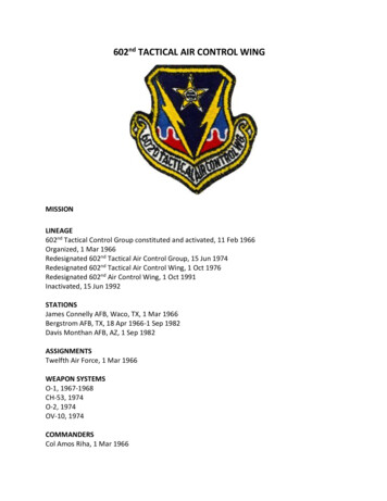
Hardware implementation for application5.1.1IBM data whitening structureAs explained earlier, CCITT data whitening processes data packets byte-per-byte, whereas IBM datawhitening processes the data packet bit-per-bit as shown in Figure 5.The process to whiten the data is similar but the result of the whitening sequence is different. The user mustensure that the same whitening algorithm is used in the devices to be compliant and establishcommunication.Figure 5. IBM data whitening polynomial5.1.2IBM data whitening exampleWhitening key:The initial value of the whitening key is set to all ones (1 1111 1111), this is 0xFF plus a ninth bit that wewill call the Most Significant Bit (MSB).The Least Significant Bit (LSB) or X0 is XOR-ed with the value of the fifth bit (X4) to generate the newMSB (refer to the MSB of line 2 in Table 1), then the whitening key is shifted one position to the right.This process counts as 1 loop. The same process must be completed eight times and the result will be theNew Whitening Key the MSB.Table 1. Whitening key processMSB (X8)X7X6X5X4X3X2X1X0CounterHex Value—111111111—0xFFStart �0000111114——1000011115——Implementing Data Whitening and CRC Verification in Software in KW01 MCUs, AN5070, Rev. 0, 07/2015Freescale Semiconductor, Inc.5
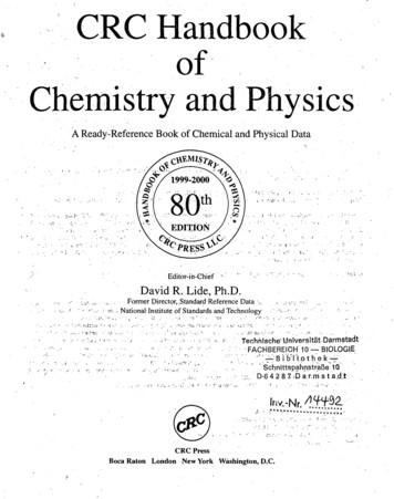
Hardware implementation for applicationTable 1. Whitening key process (continued)MSB (X8)X7X6X5X4X3X2X1X0CounterHex 0xE1New keyWhen this process is followed it will provide the following whitening keys.Table 2. IBM whitening keysByte NumberWhitening Key00xFF10xE120x1D30x9ALet’s assume that we have a four byte payload that we want to whiten as shown in Table 3.Table 3. Example 1 raw data (un-whitened)AddressData00x1110x2220x3330x44The payload (Table 3) XOR-ed with the whitening keys (Table 2) will produce the whitened data that willbe transmitted.Table 4. Example IBM whitened data results5.1.3Byte NumberWhitening KeyDataWhitened Data (XOR-ed)De-Whitened E0x3330x9A0x440xDE0x44IBM data whitening software implementationThe IBM data whitening software implementation is presented in Figure 6. This implementation can beused to either whiten or de-whiten the data.Implementing Data Whitening and CRC Verification in Software in KW01 MCUs, AN5070, Rev. 0, 07/20156Freescale Semiconductor, Inc.
Hardware implementation for applicationFigure 6. IBM data whitening in software5.2CCITT data whitening methodThis section describes the CCITT data whitening process and provides code and code examples.5.2.1CCITT data whitening structureCCITT data whitening is available in hardware for the KW01 microcontrollers, however, when a thirdparty device is required to communicate with the KW01 microcontrollers this algorithm must beimplemented in software.The data whitening process is built around a 9-bit Linear Feedback Shift Register (LFSR) used to generatea random sequence. The payload and 2-byte CRC checksum are then XORed with this random sequenceas shown in Figure 7. The data is de-whitened on the receiver side by XORing with the same randomsequence. This setup limits the number of consecutive 0’s or 1’s to nine.Payload whitening or de-whitening is thus made transparent for the user, who continues to provide andretrieve NRZ data to and from the FIFO.Figure 7. Data whitening polynomial available in hardware (CCITT whitening)Implementing Data Whitening and CRC Verification in Software in KW01 MCUs, AN5070, Rev. 0, 07/2015Freescale Semiconductor, Inc.7
Hardware implementation for application5.2.2CCITT data whitening exampleWhitening keyThe LFSR polynomial is the same polynomial as for IBM data whitening (X9 x5 1), but the whiteningprocess is executed by XORing the LSB at the output of the LFSR with the MSB of the data as shown inFigure 7.The initial value of the IBM data whitening key is set to all ones (1 1111 1111), this is 0xFF plus a ninthbit (MSB).When this process is followed, then it will provide the data whitening keys provided in Table 5.Table 5. CCITT whitening keysByte NumberWhitening Key00xFF10x8720xB830x59Let’s assume that we have the same four-byte payload (as shown in Table 3) that we want to whiten usingCCITT data whitening. That provides the whitened data by XOR-ing the CCITT data whitening keys withthe data given in Table 6.Table 6. Example CCITT data whitened results5.2.3Byte NumberWhitening KeyDataWhitened Data (XOR-ed)De-Whitened B0x3330x590x440x1D0x44CCITT data whitening software implementationThe CCITT data whitening software implementation consists of shifting the LFSR for every new bit ofdata and to XOR the LSB of the last flip-flop (X0) with the MSB of the incoming data. Thisimplementation can be used to either whiten or de-whiten the data.Implementing Data Whitening and CRC Verification in Software in KW01 MCUs, AN5070, Rev. 0, 07/20158Freescale Semiconductor, Inc.
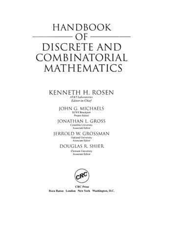
Hardware implementation for applicationFigure 8. CCITT data whitening in software5.3CRC validation in hardwareIn combination with data whitening, it is common to have a CRC validation at the end of the payload toverify the integrity of the transmission signal—that is, to validate the data received. There are two similaralgorithms widely used that enable this verification: IBM-based and CCITT- based CRC.The KW01 microcontroller’s CRC is based on the CCITT polynomial as shown in Figure 9. Thisimplementation also detects errors due to leading and trailing zeros.Figure 9. CRC validation in hardware (CCITT polynomial)This CRC algorithm is enabled in hardware by setting the CrcOn bit in RegPacketConfig1 as shown inFigure 1.5.4CRC validation in softwareWhen CRC implementation in hardware is not compatible between devices (for example, one devicesupports CCITT CRC (KW01 MCUs) and a third party device supports IBM CRC) it is also required toimplement the CRC calculation algorithm in software.To use the CRC algorithm within software the user must disable CRC calculation in hardware, this is doneby setting the CrcOn bit to zero in RegPacketConfig register.The algorithm to calculate CRC by software is shown in Figure 10.Implementing Data Whitening and CRC Verification in Software in KW01 MCUs, AN5070, Rev. 0, 07/2015Freescale Semiconductor, Inc.9
Software implementation application pre-configurationFigure 10. CRC algorithm implementation in software6Software implementation application pre-configurationThe code for this application note is based on the simple range demo application. The simple rangedemonstration runs as a standalone application that enables performing dynamic range tests.The simple demonstration consists of two nodes: TX node RX nodeIn addition to the simple range demonstration functionality a Packet Error Rate (PER) test is implemented.The PER test enables the user by way of a serial terminal interface to evaluate the performance of thecommunication between two devices.The demo can be run without a serial terminal as a range test demo. However, if the user wants to evaluatePER test then the serial terminal interface is required.Implementing Data Whitening and CRC Verification in Software in KW01 MCUs, AN5070, Rev. 0, 07/201510Freescale Semiconductor, Inc.
Software implementation application pre-configuration6.1Packet framesFor this application the radio is configured in Packet Mode (operation mode), with a variable length packetformat.Variable length packet format is selected when the PacketFormat bit is set to 1 in the RegPacketConfig1register.Figure 11. PacketFormat bit in RegPacketConfig1 registerAn illustration of a variable length packet is shown in Figure 12 and contains the following fields: Preamble (1010 ) Sync word (Network ID) Length byte Optional address byte (Node ID) Message data Optional 2 bytes CRC checksumFigure 12. Variable length packet frame used in this applicationIn this application the default variable length packet frame has been modified as shown in Figure 12. Thefollowing list provides a summary of these modifications:1. Address filtering: To disable this option set AddressFiltering bits to 00 in RegPacketConfig1.2. CRC checksum: Provided as part of the payload (not included automatically by hardware).CRC is disabled in hardware by turning off bit CrcOn from PacketConfig1.3. DC free (data whitening): Not included because it will be implemented by software.DC free is disabled in hardware by turning off DcFree bits from PacketConfig1.Implementing Data Whitening and CRC Verification in Software in KW01 MCUs, AN5070, Rev. 0, 07/2015Freescale Semiconductor, Inc.11
Software implementation application pre-configurationFigure 13. DcFree, CrcOn, and AddressFiltering fields in RegPacketConfig1 registerAfter applying the modifications as shown in Figure 13, the new packet frame identifies the CRC as nowpart of the payload.PreambleSync WordLengthMessageCRC4 Bytes4 Bytes1 Byte17 Bytes2 BytesPayloadFigure 14. Application packet framePreamble:The preample can be 0x55 or 0xAA, this is required for synchronization, the longer the synchronizationthe better the packet success rate. At least 12 bits are required for synchronization, in this application weuse 4 bytes.Sync Word (Network ID):Sync word size can be set from 1 to 8 bytes; in this application we use 4 bytes (0xF4EEF4EE).Length:1 byte for data length (0x14). 1 byte for Payload length (part of the payload) 17 payload bytes 2 bytesfor CRC (required to add CRC functionality by software)Message:17 bytes for message. 0x5A 0xA5 4 bytes for Sequence Number (little-endian) 0xCC 0xCC 0xCC 0xCC 0xCC 0xCC 0xCC 0xCC 0xCC 0xCC 0xCCImplementing Data Whitening and CRC Verification in Software in KW01 MCUs, AN5070, Rev. 0, 07/201512Freescale Semiconductor, Inc.
Application procedureCRC:2 bytes for CRC calculation by software.6.2Radio settingsThe RF default configuration for the application is show in Table 7.Table 7. Radio settings7FeatureDefault ValueCenter Frequency868 MHzBitRate50 KbpsFrequency Deviation25 KHzRxBw135 KHzModulationFSKFilterBT 1Output power13 dBmPA BoostDisabled (RFIO output)SMAC TransmissionBroadcastApplication procedureA pre-requisite to implement the software application in the Kinetis KW01 device is the Freescale TowerSystem and the TWR-RF development board. Also required is the IAR Embedded Workbench by ARMLimited.A PER test application with CRC and data whitening features by software can be found in AN5070SW.This PER test application is mounted on the simple range demo application.7.1Open the application in IAR Embedded Workbench for ARM v7.10(or newer)1. Open IAR Embedded Workbench for ARM v7.10.2. Select Open and then Workspace from the File menu and locate the folder where the project wasextracted as shown in Figure 15.Implementing Data Whitening and CRC Verification in Software in KW01 MCUs, AN5070, Rev. 0, 07/2015Freescale Semiconductor, Inc.13
Application procedureFigure 15. Opening a Workspace in IAR Embedded Workbench3. Obtain the application project AN5070SW. Extract the project, locate the folder where theapplication project was extracted.4. Select the project (SimpleRangeDemo.eww) and drag and drop it into IAR Embedded Workbenchworkspace as shown in Figure 16.Figure 16. Import the application into IAR workspace7.1.1Configure the application (TX and RX nodes)The device type and settings are configured in the application configuration file (ApplicationConf.h). Select gTxNode c for the transmitter device. (Figure 17)Implementing Data Whitening and CRC Verification in Software in KW01 MCUs, AN5070, Rev. 0, 07/201514Freescale Semiconductor, Inc.
Application procedureFigure 17. Selecting TX device in software Select gRxNode c for the receiver device. (Figure 18)Figure 18. Selecting RX device in software Select the total number of packets to send for the PER test by modifying PerTotalPackets c.(Figure 19)Figure 19. Selecting number of packets for PER test Select time delay in ms between packets in gDelayBetweenPacketsInMs c. (Figure 20)Figure 20. Selecting delay (in mili seconds) between packetsImplementing Data Whitening and CRC Verification in Software in KW01 MCUs, AN5070, Rev. 0, 07/2015Freescale Semiconductor, Inc.15
Application procedure7.1.2Run the applicationTo run the application you must connect and configure the transmit and receive nodes as follows. On the TX node: the LEDs will flash twice to indicate that this is the TX device. On the RX node: the LEDs will flash once to indicate that this is the RX device.Connect both boards to a serial terminal and configure using the parameters shown in Figure 21.Figure 21. Terminal configurationAfter the application begins it displays a message indicating that the application is waiting for the user topress switch 1 in both (TX/RX) devices.Both devices turn on LED D1 on the Freescale Tower System, TWR-RF board to indicate that theapplication has begun.Figure 22. First message in terminal in PER test RX nodeImplementing Data Whitening and CRC Verification in Software in KW01 MCUs, AN5070, Rev. 0, 07/201516Freescale Semiconductor, Inc.
Application procedureFigure 23. First message in terminal in PER test TX nodePress switch 1 in RX node to begin the receive process.Figure 24. Running message in PER test RX nodePress switch 2 in TX node to begin transmitting packets.Figure 25. Running message in PER test TX nodeImplementing Data Whitening and CRC Verification in Software in KW01 MCUs, AN5070, Rev. 0, 07/2015Freescale Semiconductor, Inc.17
Application procedure7.1.3Identify application behaviorThe application behavior for transmit and receive nodes is identified as follows.On the TX node: LED D4 from the TWR-RF board flashes when a packet has been transmitted.On the RX node: LED D4 from the TWR-RF board flashes when a valid CRC is identified, and LED D2flashes for an invalid CRC.When the PER test is completed, the results of the test can be viewed in the terminal and the user has theoption to restart the test by pressing software switch 1 as shown in Figure 26.Figure 26. PER test finished message in TX nodeFigure 27. PER test finished message in RX nodeImplementing Data Whitening and CRC Verification in Software in KW01 MCUs, AN5070, Rev. 0, 07/201518Freescale Semiconductor, Inc.
Summary of software implementation8Summary of software implementationIn brief, to apply data whitening and CRC verification to your application with software use the followingthe sequences:For TX:1. Calculate CRC of the payload starting from the data length byte, but do not include the last twobytes (those are reserved to store the CRC calculation result).2. Include the CRC calculation to the last two bytes of the payload.3. Compute data whitening to the entire payload buffer (including the last two CRC bytes).4. Transmit the message.For RX:1. Compute data de-whitening to the reception buffer.2. Calculate CRC verification to this de-whitened buffer, but do not include the last two CRC bytes.3. Compare the result of this CRC calculation to the CRC of the reception buffer (last two bytes ofthis buffer).4. If the CRC is equal, then the reception process continues to Successful RX packet; if the CRC isnot equal then the process goes to CRC Error Indication.9ConclusionsFull compatibility in hardware among products in the market is a rare. To overcome these constraintssoftware implementations such as the data whitening and CRC verification discussed in this document arenecessary to enable devices to communicate with each other regardless of the limitation in hardware.Prior to implementing data whitening and CRC verification by software, the programmer must disable thisfunctionality in the device hardware by writing to the corresponding registers.10 ReferencesThe chapters within this application note summarize the important details of each topic. For more detailson the specific topics within this document, see the device reference manual, specifically for informationand details about the KW01 transceiver’s registers and device hardware capabilities. Kinetis Sub-1 GHz Low Power Transceiver plus Microcontroller Reference Manual (DocumentNumber: MKW01xxRM)A PER test application with CRC and data whitening is located at www.freescale.com with the filename: AN5070SW11 Revision historyRevision 0 is the initial release of this application note.Implementing Data Whitening and CRC Verification in Software in KW01 MCUs, AN5070, Rev. 0, 07/2015Freescale Semiconductor, Inc.19
How to Reach Us:Information in this document is provided solely to enable system and softwareHome Page:freescale.comimplementers to use Freescale products. There are no express or implied copyrightWeb Support:freescale.com/supportinformation in this document.licenses granted hereunder to design or fabricate any integrated circuits based on theFreescale reserves the right to make changes without further notice to any productsherein. Freescale makes no warranty, representation, or guarantee regarding thesuitability of its products for any particular purpose, nor does Freescale assume anyliability arising out of the application or use of any product or circuit, and specificallydisclaims any and all liability, including without limitation consequential or incidentaldamages. “Typical” parameters that may be provided in Freescale data sheets and/orspecifications can and do vary in different applications, and actual performance mayvary over time. All operating parameters, including “typicals,” must be validated foreach customer application by customer’s technical experts. Freescale does not conveyany license under its patent rights nor the rights of others. Freescale sells productspursuant to standard terms and conditions of sale, which can be found at the followingaddress: freescale.com/SalesTermsandConditions.Freescale, the Freescale logo, and Kinetis are trademarks of FreescaleSemiconductor, Inc., Reg. U.S. Pat. & Tm. Off. All other product or service names arethe property of their respective owners. ARM, Cortex, and IAR Embedded Workbenchare registered trademarks of ARM Limited. 2015 Freescale Semiconductor, Inc.Document Number: AN5070Rev. 007/2015
5.1.3 IBM data whitening software implementation The IBM data whitening software implementation is presented in Figure 6. This implementation can be used to either whiten or de-whiten the data. 1 1 00 00 11 1 6 — — 1 1 10 00 01 1 7 — — y 1 e 1 k11 00w 00e 11 N E 8 x 0 Table 2. IBM whitening keys Byte Number Whitening Key 0 0xFF 1 0xE1 2 .