Transcription
Lesson 8: A Compound Spur Gear Train
Goal: -Create Assembly-Create Proper Gear Mates-Create Motion Study-Graph Angular velocity of Output GearMAKE SURE YOU ARE IN MILLIMETERS FOR THIS EXERCISECreating Assembly:Parts List:gbox housinggbox inputgbox middlegbox outputTo start off, make the gear housing your base part. Labeled (gbox housing)Next, mate the gbox input to the gbox housing
Create a concentric mate with top hole
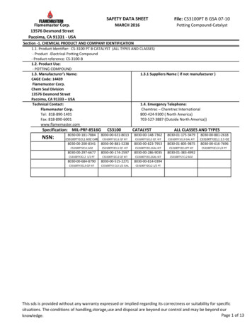
Create a coincident mateSelect the partgbox middle and repeatthe mates for itscorresponding holeNote: For the middle gearmake sure the back of thehousing is mated correctlyand not with the outermost edge. When matedcorrectly, the gear shouldprotrude out the back alittle bit (see below)Next, insert the output gear with a corresponding coincident and concentric mate.
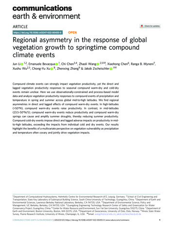
When you’re done it should look like this. IMPORTANT NOTE: Solidworks doesn’t care if gearteeth don’t mesh. The Simulation will run even if the gear teeth are going into each other. Thisis why we need to do gear mates so that we relate the rotation of one gear to another. So if youwant the teeth to visually mesh (they won’t mesh absolutely perfectly) just go in with yourmouse and rotate the gears until you are satisfied.
Create Gear Mates:Before starting, select view and underneath select the Axes option, this will show theaxes of the gears. This is necessary for properly mating the gears. Now,select Mate andunderneath the common mates are two tabs labeled Advanced Mates and Mechanical Mates,Select Mechanical Mates. Then Select Gear.
We need to first relate the input gear to the middle gear. With the gear mate open, select theaxis of the top gear and middle gear. On the left, two boxes labeled ratios, will turn yellow, thiswhere you type in the nominal diameters of the gears. In this case we type 50mm and 120mm.Click OK.Now for the middle Gear and the output gear, select their axes and type in 60mm and 125 mmfor their ratios. If you’re wondering about which box to put which ratio, notice the labels on thegears in the model space, they will show what you labeled which. Click OK. You can now movethe gear with your mouse if you want to visually see if the ratios are right.
Creating Motion StudyThe goal now is to create a motion study in which you turn the input gear at 60 RPM for 1second.The first step is to go into motion study, you can either select Motion Study 1 from the bottomof the screen or select New Motion Study from the Assembly tab between Reference Geometryand Bill of Materials.The Motion Study will pop up on the bottom of yourscreen. Now to create the 60 RPM at the input gear. Select Motor (the yellow icon) and thenselect Axis 1 and type in 60 RPM under the motion section. A red arrow will appear showing thedirection. In the Component/Direction box, there is a button with two arrows. Clicking this willswitch the direction of the 60 RPM if you select it. Click OK. Once that is done, click theRecalculate button (blue/yellow icon) and watch the gears turn.If the animation seems a bit choppy, select the Motion Study Properties button and raise theframes per second (for example 60 fps).
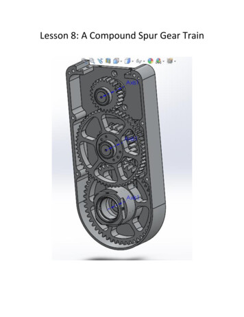
Graph Angular Velocity of Output GearStart by Selecting Solidworks Motion from the Office Products tab at the top of thescreen. This will ensure that certain options are available for graphing to work.First, we need to make sure the frames per second are at 60. Do this by selectingMotion Study Properties and changing fps to 60, then click calculate.SolidworksMotionMotion Study PropertiesCalculateNext, Right click on the output gear in the Motion Manager Tree (Bottom Left) and click theoption Create Motion Plot. A menu will appear (shown below). Fill in the information as seen inthe below picture and click OK. A plot will appear showing the angular velocity which is 72degrees per second.This concludes Lesson 8
Now,select Mate and underneath the common mates are two tabs labeled Advanced Mates and Mechanical Mates, Select Mechanical Mates. Then Select Gear. We need to first relate the input gear to the middle gear. With the gear mate open, select the axis of the top gear and middle gear. On the left, two boxes labeled ratios, will turn yellow, this