Transcription
UNIT-1SINGLE-PHASE INDUCTION MOTORS1.1 INTRODUCTION:There are two basic reasons for the use of single-phase motors rather than 3-phase motors.1. For reason of economy, most houses, offices and also rural areas are supplied with singlephase a.c, as power requirements of individual load items are rather small.2. The economics of the motor and its branch circuit. Fixed loads requiring not more than 0.5KW can generally be served most economicallywith single phase power and a single phase motor. Single phase motors are simple in construction, reliable, easy to repair and comparativelycheaper in cost and therefore, find wide use in fans, refrigerators, vacuum cleaners,washing machines, other kitchen equipment, tools, blowers, centrifugal pumps, smallfarming appliances etc.Because of above reasons motors of comparatively small ratings (mostly in fractionalKW ratings) are manufactured in large number to operate on single phase ac at standardfrequencies. An indication of the number of such motors can be had from the fact that the sum oftotal of all fractional kilowatt motors in use today far exceeds the total of integral kilowattmotors of all types.1.2 TYPES OF SINGLE-PHASE MOTOR:The Single phase motors may be of the following types:1. Single-phase Induction Motors:A. Split-phase motors(i)Resistance-start motor(ii)Capacitor-start motor(iii) Permanent-split (single-value) capacitor motor(iv)Two-value capacitor motor.B. Shaded-pole induction motor.
C. Reluctance-start induction motor.D. Repulsion-start induction motor.2. Commutator-Type, Single-Phase Motors:A. Repulsion motor.B. Repulsion-induction motor.C. A.C series motor.D. Universal motor.3. Single-phase Synchronous Motors:A. Reluctance motor.B. Hysteresis motor.C. Sub-synchronous motor.1.3 SINGLE-PHASE INDUCTION MOTORSApplications and Disadvantages:1.31 Applications: Single phase induction motors are in very wide use in industry especially in fractionalhorse-power field.They are extensively used for electrical drive for low power constant speed apparatussuch as machine tools, domestic apparatus and agricultural machinery in circumstanceswhere a three-phase supply is not readily available. Single phase induction motors sizes vary from 1/400 kw to 1/25 kw are used in toys, hairdryers, vending machines etc. Universal motor is widely used in portable tools, vacuum cleaners& kitchen equipment.1.32 Disadvantages:Though these machines are useful for small outputs, they are not used for large powers asthey suffer from many disadvantages and are never used in cases where three-phase machinescan be adopted.The main disadvantages of single-phase induction motors are:1. Their output is only 50% of the three-phase motor, for a given frame size andtemperature rise.
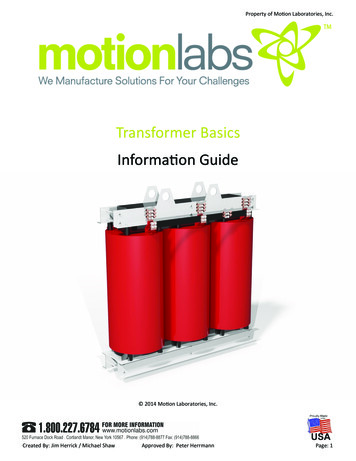
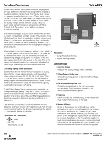
2. They have lower power factor.3. Lower efficiency.4. These motors do not have inherent starting torque.5. More expensive than three-phase motors of the same output.6. Low overload capacity.1.4 CONSTRUCTION OF SINGLE PHASE INDUCTION MOTOR:Single phase induction motor is very simple and robust in construction. The statorcarries a distributed winding in the slots cut around the inner periphery. The stator conductorshave low resistance and they are winding called Starting winding is also mounted on the stator.This winding has high resistance and its embedded deep inside the stator slots, so that they haveconsiderable inductance. The rotor is invariably of the squirrel cage type. In practice, in order toconvert temporarily the single phase motor into two-phase motor, auxiliary conductors areplaced in the upper layers of stator slots. The auxiliary winding has a centrifugal switch in serieswith it. The function of the switch is to cut off the starting winding, when the rotor hasaccelerated to about 75% of its rated speed. In capacitor-start motors, an electrolytic capacitor ofsuitable capacitance value is also incorporated in the starting winding circuit.The main stator winding and auxiliary (or starting) winding are joined in parallel, andthere is an arrangement by which the polarity of only the starting winding can be reversed. Thisis necessary for changing the direction of rotation of the rotor.Fig: 1.41
A 1-phase induction motor is similar to a 3-phase squirrel cage induction motor inphysical appearance. The rotor is same as that employed in 3-phase squirrel cage inductionmotor. There is uniform air gap between stator and rotor but no electrical connection betweenthem.Although single phase induction motor is more simple in construction and is cheaperthan a 3-phase induction motor of the same frame size, it is less efficient and it operates atlower power factor.1.5 WORKING OF SINGLE-PHASE INDUCTION MOTOR:A single phase induction motor is inherently not self-staring can be shown easily.Consider a single phase induction motor whose rotor is at rest. Let a single phase a.c. source beconnected to the stator winding (it is assumed that there is no starting winding). Let the stator bewound for two poles.When power supply for the stator is switched on, an alternating current flows throughthe stator winding. This sets up an alternating flux. This flux crosses the air gap and links withthe rotor conductors. By electromagnetic induction e.m.f.’s are induced in the rotor conductors.Since the rotor forms a closed circuit, currents are induced in the rotor bars. Due to interactionbetween the rotor induced currents and the stator flux, a torque is produced. It is readily seen thatif all rotor conductors in the upper half come under a stator N pole, all rotor conductors in thelower half come under a stator S pole. Hence the upper half of the rotor is subjected to a torquewhich tends to rotate it in one direction and the lower half of the rotor is acted upon by an equaltorque which tends to rotate it in the opposite direction. The two equal and opposite torquescancel out, with the result that the net driving torque is zero. Hence the rotor remains stationary.Thus the single phase motor fails to develop starting torque.This argument holds good irrespective of the number of stator poles and the polarity ofthe stator winding. The net torque acting on the rotor at standstill is zero.If, however, the rotor is in motion in any direction when supply for the stator isswitched on, it can be shown that the rotor develops more torque in that direction. The net torquethen, would have non-zero value, and under its impact the rotor would speed up in its direction.
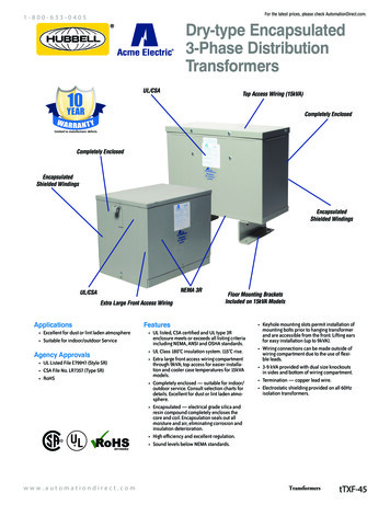
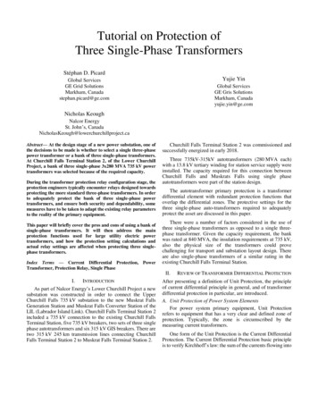
The analysis of the single phase motor can be made on the basis of two theories:i. Double revolving field theory, andii. Cross field theory.1.51 DOUBLE REVOLVING FIELD THEORY:This theory makes use of the idea that an alternating uni-axial quantity can berepresented by two oppositely-rotating vectors of half magnitude. Accordingly, an alternatingsinusoidal flux can be represented by two revolving fluxes, each equal to half the value of the120 𝑓alternating flux and each rotating synchronously (𝑁𝑠 𝑃) in opposite direction.As shown in figure: (a) let the alternating flux have a maximum value of 𝜙𝑚 . Itscomponent fluxes A and B will each equal to 𝜙𝑚 /2 revolving in anti-clockwise and clockwisedirections respectively.After some time, when A and B would have rotated through angle Ɵ and – Ɵ, as infigure: (b), the resultant flux would beϕm 2*2cos2Ɵ2 ϕm cos ƟAfter a quarter cycle of rotation, fluxes A and B will be oppositely-directed as shownin figure: (c) so that the resultant flux would be zero.Fig: 1.51(a)Fig: 1.51(b)Fig:1.51 (c)
Fig: 1.51 (d)Fig: 1.51(e)After half a cycle, fluxes A and B will have a resultant of -2*ϕm2 -ϕm. After threequarters of a cycle, again the resultant is zero, as shown in figure: (e) and so on. If we plot thevalues of resultant flux against Ɵ between limits Ɵ 00 to Ɵ 3600 , then a curve similar to theone shown in figure: (f) is obtained. That is why an alternating flux can be looked upon ascomposed of two revolving fluxes, each of half the value and revolving synchronously inopposite directions.Fig: 1.51(f)It may be noted that if the slip of the rotor is S with respect to the forward rotating flux(i.e. one which rotates in the same direction as rotor) then its slip with respect to the backwardrotating flux is (2-S).
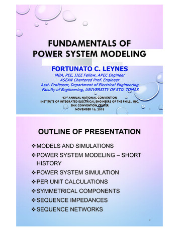
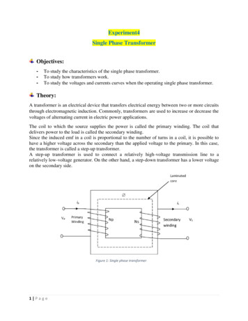
Each of the two component fluxes, while revolving round the stator, cuts the rotor,induces an e.m.f. and this produces its own torque. Obviously, the two torques (called forwardand backward torques ) are oppositely-directed, so that the net or resultant torques is equal totheir difference as shown in fig: (g)Fig: 1.51(g) Torque-Speed characteristics1 SNow, power developed by a rotor is Pg (S) I22 R 2If N is the rotor r.p.s., then torque is given by , Tg 12ΠN1 S(S) I22 R 2Now, N Ns (1-S)Therefore, Tg 1I22 R22ΠNsS kI22 R2SHence, the forward and backward torques are given byTf korTotal torqueTf I22 R2I22 R2SSsynch. WattT Tf TbandandTb -kTb -I22 R2(2 S)I22 R2(2 S)synch. Watt
Fig: (g) shows both torques and the resultant torque for slips between zero and 2. At standstill,S 1 and (2-S) 1. Hence, Tf and Tb are numerically equal but, being oppositely directed,produce no resultant torque. That explains why there is no starting torque in a single-phaseinduction motor.However, if the rotor is started somehow, say, in the clockwise direction, theclockwise torque starts increasing and, at the same time, the anticlockwise torque startsdecreasing. Hence, there is a certain amount of net torque in the clockwise direction whichaccelerates the motor to full speed.1.6 EQUIVALENT CIRCUIT:The equivalent circuit of a single phase induction motor can be developed on the basisof two revolving field theory. To develop the equivalent circuit it is necessary to considerstandstill or blocked rotor conditions.The motor with a blocked rotor merely acts like a transformer with its secondary shortcircuited and its equivalent circuit will be as shown in fig: 1.6 (a), Em being e.m.f. induced in thestator.Fig:1.6 (a) Equivalent Circuit of a Single Phase Induction MotorThe motor may now be viewed from the point of view of the two revolving fieldtheory. The two flux components induce e.m.f. Emf and Emb in the respective stator winding.Since at standstill the two oppositely rotating fields are of same strength, the magnetizing androtor impedances are divided into two equals halves connected in series as shown in figure:1.6(b)
Fig:1.6 (b) Equivalent Circuit of Single Phase Induction Motor atStandstill on the basis of Two Revolving Field TheoryWhen the rotor runs at speed N with respect to forward field, the slip is S w.r.t.forward field and (2-S) w.r.t. backward field and the equivalent circuit is as shown in fig:1.6(c)Fig:1.6 (c) Equivalent Circuit of a Single Phase Induction MotorUnder Normal Operating ConditionsIf the core losses are neglected the equivalent circuit is modified as shown infig:1.6(d). The core losses, here, are handled as rotational losses and subtracted from the powerconverted into mechanical power; the amount of error thus introduced is relatively small.
Fig:1.6 (d) Approximate Equivalent Circuit of a Single Phase Induction MotorUnder Normal Operating Conditions1.7 STARTING METHODS OF SINGLE-PHASE INDUCTION MOTORS:A single-phase induction motor with main stator winding has no inherent startingtorque, since main winding introduces only stationary, pulsating air-gap flux wave. For thedevelopment of starting torque, rotating air-gap field at starting must be introduced. Severalmethods which have been developed for the starting of single-phase induction motors, may beclassified as follows:a) Split-phase starting.b) Shaded-pole starting.c) Repulsion-motor starting andd) Reluctance starting.A single-phase induction motor is commonly known by the method employed for its starting.The selection of a suitable induction motor and choice of its starting method, depend upon thefollowing:(i) Torque-speed characteristic of load from standstill to the normal operating speed.(ii) The duty cycle and(iii)The starting and running line-current limitations as imposed by the supply authorities.
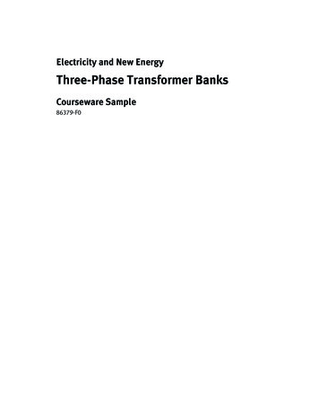
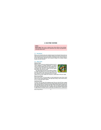
1.7 (a) SPLIT-PHASE STARTING:Single-phase induction motors employing this method of starting are called Splitphase motors. All the split-phase motors have two stator windings, a main (or running)winding and an auxiliary (or starting) winding. Both these windings are connected in parallelbut their magnetic axes are space displaced by 900 electrical.It is known that when two windings spaced 900 apart on the stator, are excited by twoalternating e.m.f. that are 900 displaced in time phase, a rotating magnetic field is produced.If two windings so placed are connected in parallel to a single phase source, the fieldproduced will alternate but will not revolve since the two windings are equivalent to onesingle phase winding. If impedance is connected in series with one of these windings, thecurrents may be made to differ in time phase, thereby producing a rotating field. This is theprinciple of phase splitting. Split phase motors are of following types.1. Resistor-split phase motors2. Capacitor split-phase motors3. Capacitor start and run motors4. Capacitor-run motors1.71 RESISTOR SPLIT-PHASE MOTORS:The stator of a split-phase induction motor is provided with an auxiliary or startingwinding S in addition to the main or running winding M. The starting winding is located 90 electrical from the main winding [See figure: 1.71(a)] and operates only during the brief periodwhen the motor starts up. The two windings are so designed that the starting winding S has ahigh resistance and relatively small reactance while the main winding M has relatively lowresistance and large reactance as shown in the schematic connections in figure: 1.71(b).Consequently, the currents flowing in the two windings have reasonable phase difference (25 to30 ) as shown in the phasor diagram in figure: 1.71(c).Operation(i)When the two stator windings are energized from a single-phase supply, the mainwinding carries current Im while the starting winding carries current Is
(ii)Since main winding is made highly inductive while the starting winding highlyresistive, the currents Im and Is have a reasonable phase angle a (25 to 30 )between them as shown in figure: 1.71(c).Consequently, a weak revolving fieldapproximating to that of a 2-phase machine is produced which starts the motor. Thestarting torque is given by;Ts k Im Is sinɸWhere k is a constant whose magnitude depends upon the design of the motor .When the motor reaches about 75% of synchronous speed, the centrifugal switch opens thecircuit of the starting winding. The motor then operates as a single-phase induction motor andcontinues to accelerate till it reaches the normal speed. The normal speed of the motor is belowthe synchronous speed and depends upon the load on the motor.Characteristics:(i)The sinning torque is 15 to 2 times the full-loud torque mid (starting current is 6 to 8times the full-load current.(ii) Due to their low cost, split-phase induction motors are most popular single phase motorsin the market.(iii) Since the starting winding is made of fine wire, the current density is high and thewinding heats up quickly. If the starting period exceeds 5 seconds, the winding may burnout unless the motor is protected by built-in-thermal relay. This motor is, therefore,suitable where starting periods are not frequent.An important characteristic of these motors is that they are essentially constant-speed motors.The speed variation is 2-5% from no-load to full-load
Fig: 1.71(a)Fig: 1.71(b)Fig: 1.71(c)Applications:These motors are suitable where a moderate starting torque is required and where startingperiods are infrequent e.g., to drive:a. Fansb. washing machinesc. oil burnersd. Small machine tools etc.The power rating of such motors generally lies between 60 W and 250 W .
1.72 Capacitor split-phase motors (or) Capacitor start motors:The capacitor split-phase motor is identical to a resistor split-phase motor except that the startingwinding has as many turns as the main winding. Moreover, a capacitor C is connected in serieswith the starting winding as shown in figure: 1.72(a).The value of capacitor is so chosen thatIs leads Im by about 80 (i.e., ɸ 80 ) which is considerably greater than 25 found in resistorsplit-phase motor [See figure: 1.72(b).Consequently, starting torque (Ts k ImIs sinɸ)ismuch more than that of a split-phase motor Again, the starting winding is opened by thecentrifugal switch when the motor attains about 75% of synchronous speed. The motor thenoperates as a single-phase induction motor and continues to accelerate till it reaches the normalspeed.Characteristics(i) Although starting characteristics of a capacitor-start motor are better than those of aresistor split-phase motor, both machines possess the same running characteristicsbecause the main windings are identical.(ii) The phase angle between the two currents is about 80 compared to about 25 in aresistor split-phase motor. Consequently, for the same starting torque, the current in thestarting winding is only about half that in a resistor split-phase motor. Therefore, thestarting winding of a capacitor start motor heats up less quickly and is well suited toapplications involving either frequent or prolonged starting periods.
Fig: 1.72(a)Fig: 1.72(b)Applications:Since the motors possess high-starting torque, these motors are used fora. Refrigeratorsb. Air-conditionersc. Compressorsd. Reciprocating pumpse. Other loads requiring high-starting torques.The power rating of such motors lies between 120 W and 750W.1.73 Capacitor-Start and Capacitor-Run motors:This motor is identical to a capacitor-start motor except that starting winding is not opened afterstarting so that both the windings remain connected to the supply when running as well as atstarting. Two designs are generally used.
(i) In one design, a single capacitor C is used for both starting and running as shown in fig:1.73(a).This design eliminates the need of a centrifugal switch and at the same timeimproves the power factor and efficiency of the motor.(ii) In the other design, two capacitors C1 and C2 are used in the starting winding as shownin fig: 1.73(b). The smaller capacitor C1 required for optimum running conditions ispermanently connected in series with the starting winding. The much larger capacitor C2is connected in parallel with C1 for optimum starting and remains in the circuit duringstarting. The starting capacitor C1 is disconnected when the motor approaches about75% of synchronous speed. The motor then runs as a single-phase induction motor.Characteristics(i) The starting winding and the capacitor can be designed for perfect 2-phase operation atany load. The motor then produces a constant torque and not a pulsating torque as inother single-phase motors.(ii) Because of constant torque, the motor is vibration free.Applications:a. Hospitalsb. Studios andc. Other places where silence is important.Fig: 1.73(a)Fig: 1.73 (b)
Fig: 1.73 (c)Fig: 1.73 (d)The power rating of such motors lies between 100 to 400 watts1.74 Capacitor-run motors:This motor is also called permanent split capacitor motor. The same capacitor is keptpermanently in series with auxiliary winding both at starting and under running conditions asillustrated in figure: 1.74 (a). There is no centrifugal switch. At a particular desired load, thecapacitor and auxiliary winding can be so designed as to result in 900 time-phase displacementbetween the two winding currents. In such a case, the motor would operate as a balanced twophase induction motor, backward rotating flux would, therefore, be absent and the motor wouldhave improved efficiency and better operating power factor. Since backward rotating field canbe reduced to zero, the pulsating torque due to interaction between forward and backwardrotating fields is absent and this results in a quiet motor.
Fig: 1.74 (a)Fig: 1.74 (b)In these motors, the value of permanent capacitor is so chosen as to obtain acompromise between the best starting and running conditions. A typical torque-speedcharacteristic is shown in fig: 1.74 (b)These motors are used where quiet operation is essential as ina. Officesb. Class roomsc. Theatersd. Ceiling fans, in which the value of capacitance varies from 2 to 3µF.1.8 Shaded-Pole Motor:The shaded-pole motor is very popular for ratings below 0.05 H.P. ( 40 W) because ofits extremely simple construction. It has salient poles on the stator excited by single-phase supplyand a squirrel cage rotor as shown in figure: 1.8(a). A portion of each pole is surrounded by ashort-circuited turn of copper strip called shading coil.
Fig: 1.8(a)The operation of the motor can be understood by referring to figure: 1.8(b) which showsone pole of the motor with a shading coil.(i)During the portion OA of the alternating-current cycle [See figure: 1.8(b)(i)], the fluxbegins to increase and an e.m.f. is induced in the shading coil. The resulting current inthe shading coil will be in such a direction (Lenz’s law) so as to oppose the change influx. Thus the flux in the shaded portion of the pole is weakened while that in theunshaded portion is strengthened as shown in figure: 1.8(b)(ii)(ii)During the portion AB of the alternating-current cycle, the flux has reached almostmaximum value and is not changing. Consequently, the flux distribution across thepole is uniform [See figure: 1.8(b)(iii)] since no current is flowing in the shading coil.As the flux decreases (portion BC of the alternating current cycle), current is inducedin the shading coil so as to oppose the decrease in current. Thus the flux in the shadedportion of the pole is strengthened while that in the unshaded portion is weakened asshown in figure: 1.8(b)(iv)
Fig: 1.8(b)(iii)The effect of the shading coil is to cause the field flux to shift across the pole facefrom the unshaded to the shaded portion. This shifting flux is like a rotating weakfield moving in the direction from unshaded portion to the shaded portion of the pole.(iv)The rotor is of the squirrel-cage type and is under the influence of this moving field.Consequently, a small starting torque is developed. As soon as this torque starts torevolve the rotor, additional torque is produced by single-phase induction-motoraction. The motor accelerates to a speed slightly below the synchronous speed andruns as a single-phase induction motor.Characteristics(i) The salient features of this motor are extremely simple construction and absenceof centrifugal switch.(ii) Starting torque, efficiency and power factor are very lowApplications:These motors are only suitable for low power applications e.g., to drive:a. small fansb. Toysc. Hair driersd. Desk fans etc.The power rating of such motors is upto about 30 W.
1.9 A.C. SERIES MOTOR (or) UNIVERSAL MOTOR:A d.c. series motor will rotate in the same direction regardless of the polarity of thesupply. One can expect that a d.c. series motor would also operate on a single-phase supply. It isthen called an a.c. series motor. However, some changes must be made in a d.c. motor that is tooperate satisfactorily on a.c. supply. The changes effected are:(i) The entire magnetic circuit is laminated in order to reduce the eddy current loss. Hencean a.c. series motor requires a more expensive construction than a d.c. series motor.(ii) The series field winding uses as few turns as possible to reduce the reactance of the fieldwinding to a minimum. This reduces the voltage drop across the field winding.(iii) A high field flux is obtained by using a low-reluctance magnetic circuit.(iv) There is considerable sparking between the brushes and the commutator when the motoris used on a.c. supply. It is because the alternating flux establishes high currents in thecoils short-circuited by the brushes. When the short-circuited coils break contact from thecommutator, excessive sparking is produced. This can be eliminated by using highresistance leads to connect the coils to the commutator segments.Construction:The construction of an a.c. series motor is very similar to a d.c. series motor except thatabove modifications are incorporated [See figure:1.91]. such a motor can be operated either ona.c. or d.c. supply and the resulting torque-speed curve is about the same in each case. For thisreason, it is sometimes called a universal motor.
Fig: 1.91OperationWhen the motor is connected to an a.c. supply, the same alternating current flows throughthe field and armature windings. The field winding produces an alternating fluxthat reactswith the current flowing in the armature to produce a torque. Since both armature current andflux reverse simultaneously, the torque always acts in the same direction. It may be noted that norotating flux is produced in this type of machines; the principle of operation is the same as that ofa d.c. series motor.CharacteristicsThe operating characteristics of an a.c. series motor are similar to those of a d.c. series motor.(i) The speed increases to a high value with a decrease in load. In very small series motors,the losses are usually large enough at no load that limits the speed to a definite value(1500 - 15,000 r.p.m.).(ii) The motor torque is high for large armature currents, thus giving a high starting torque.(iii) At full-load, the power factor is about 90%. However, at starting or when carrying anoverload, the power factor is lower.ApplicationsThe fractional horsepower a.c. series motors have high-speed (and corresponding small size) andlarge starting torque. They can, therefore, be used to drive:a) high-speed vacuum cleaners
b) sewing machinesc) electric shaversd) drillse) Machine tools etc.
SINGLE-PHASE INDUCTION MOTORS 1.1 INTRODUCTION: There are two basic reasons for the use of single-phase motors rather than 3-phase motors. 1. For reason of economy, most houses, offices and also rural areas are supplied with single phase a.c, as power r