Transcription
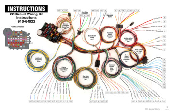
INSTRUCTIONS22 Circuit Wiring KitInstructions910-64022Fuse Box Connections16(viewed from A106 2018, Speedway Motors, Inc.1910-64022 2017
INSTRUCTIONS22 Circuit Wiring KitInstructions910-64022Fuse Panel, Engine CompartmentFront of Vehicle Connections1. Run the dark green horn feed [29] wire to the positive connection on your horn.2. Run the orange electric fan wire [300] to a fan relay. Wire to terminal 85 of the relay.DO NOT use as direct power for the fan.Run power direct from battery with in-line fuse based on fan specs. (wire/fuse not included)3. Run the light green headlight high beam [11A] and tan headlight low beam [12] to the front of thevehicle. You will have to splice this wire so you can run it to both headlights. Connect these wiresalong with the headlight ground wires to the connectors as per the diagram on this page.4. Run the dark green water temp sender [35] to the water temperature sender.5. Run the dark blue oil pressure sender wire [31] to the oil pressure sender.6. Run the pink ignition feed [3A] wire to either the battery side of a GM HEI distributor or the ballastresistor on a points style distributor. If you’re using an after market ignition modules please followits instructions for specific directions.7. Run the white wiper feed wire [93] to the wiper motor positive side connection.8. Run the brown park lights [9A] wire to a splice then to both of the front park lights. If you are usinga duel filament bulb it should be connected to the low filament.9. Run the white coil-tachometer wire [121] wire to the tach terminal on a GM HEI distributor, thenegative side of the coil, or to a tach connector on a after market ignition module.10. Run the dark blue right front turn [15A] to the right front directional lamp. This would be connectedto the high side if you’re using a dual filament bulb for park/turn.11. Run the light blue left front turn [14A] to the left front directional lamp. This would be connected tothe high side if you’re using a dual filament bulb for park/turn.WIRE #COLORPRINTINGFuse Panel11ALight GreenHeadlight High Beam14ALight BlueLeft Front Turn9ABrownPark LightsThis fuse panel is designed to be mounted under a dash away from theelements. It should not be exposed to the elements.OrangeElectric FanHorn and Dimmer PlugsDark BlueOil PressureRoute the dome light ground wire [156] to the dome light. This wireallows the headlight switch to turn on the dome light.PinkIgnition15ADark Blue29Dark Green35Dark Green93White300313A12140A156Right Front TurnHornWater TempWiperWhiteTachometerGrayDome GroundOrangeDomeInsure the dome light feed wire [40A] is routed to the proper location.This system uses a switched ground system for the dome light usingthe headlight switch and door switches.Plug the horn relay and dimmer switch into their respective connectors.Active fuses based on Power:BatteryPower:Brake LightsPower LocksClockPower SeatsHazardParking LightsPower er:GaugesFuel PumpWipersCruiseTurn Signals 2018, Speedway Motors, Inc.2910-64022 2017
INSTRUCTIONS22 Circuit Wiring KitInstructions910-64022Rear, Power, Brakes and AccessoryPower and Brake ConnectionsConnect the main battery wire [2A] to the “bat” stud on a GM starter solenoid orthe battery side of a ford starter relay. Use the included fusible link wire marked12V battery, to perform this task.Run the orange brake switch wire [40B] to the input side of the brake light switchRun the white brake switch wire [17A] to the output side of the brake light switchRear ConnectionsRun the tan gas gauge [30] wire to the sending unit onthe fuel tank.Run the yellow left rear turn signal wire [18] to the leftrear directional light. This should be connected to thehigh side of a dual filament bulb.189B1930Rear Running LightsurnRight Rear TaugeGas G17B610ACCESSORY FEED WIRE CONNECTIONWIRE #TYPECOLORPRINTING102BatteryOrange12 Volt Battery Fused103IgnitionTanFuel Pump104BatteryOrangePower Seats105BatteryRedPower Locks106IgnitionPinkPower Windows107 AccessoryBrownIgnition Sw Accy5104102107The kit is designed with 5 accessory fused circuits. Theseare all plugged into one plug, the kit includes the spadesrequired to attach into this plug.ghtBrakeBraAccessoryFeed WireConnections10Accessory WiresRear BodyFeed Wireske LiBraThirdRun the dark green right rear turn signal wire [19] to theright rear directional light. This should be connected tothe high side of a dual filament bulb.Run the brown rear running lights [9B] to the rear of thevehicle, it will need to be spliced to run to both lights.This wire should be connected to the low side of a dualfilament bulb.rSendeRun the light blue third brake light wire [17B] to the output side of the brake lightswitch if using a third brake light. If you are not using a third brake light this wirecan be removed or taped into the harness.103keThBrake SwitchWiresMain Wiring BundleRun the light blue third brake light wire [17B] to the thirdbrake light positive side. If you are not using a thirdbrake light this wire can be either taped into the harnessor removed.Left Rear TurnirdSwitch40BSwBritchakeL17Aight17B12 V Battery2AMain PowerFeed from ADLIGHT SWITCH CONNECTORWIRE WhitePRINTINGCourtesy GroundFull-time front parking lamp(parking lights stay on with headlights)Dash LightsBatteryBrownRear Running LightsOrangeFused BatteryYellowBrownDimmer SwitchFront Parking Lamp(parking lights off with headlights are on) 2018, Speedway Motors, Inc.3910-64022 2017
Ground82600140180Oil PressTachometer2102500408010209. ESpeedometerFuel6816Volts.57.½ .120 13011014430120 10 20 30 400860 7 0 90 10501Dash Lights100150.22 Circuit Wiring KitInstructions910-64022Instrument ClusterF .INSTRUCTIONSTempSymbol for GroundINSTRUMENT CLUSTER WIRINGHIGH BEAM ighBeamRiInghdtTurnLeInft TdurnIndGas Gauge SenderGrayDash Lights8RIGHT TURN INDTachometerTanBlack8Oil Pressure30150150Water TempPurplePink35Right Front Turn4013931Oil PressureWhiteCoil to Tachometer121Dark BluerDark Green31ende35ge SLeft Front Turn121GauLight Blue30Gas14BDark BluetionHeadlight High BeamIgniLight Green12 VPRINTING11B15BalCOLORSignWIRE #39LEFT TURN INDVSSThe diagram above shows a typical electrical gauge wiringsystem. If you use a mechanical speedometer you will onlyrequire the gauge lighting to go to it, same for a mechanicaltachometer. Vehicle speed sensor wires are supplied inthe sub kit 910-64027-4, for mechanical speedometersthese can be ignored. Always follow gauge manufacturesinstructions and vehicle speed sensor instructions forspecific installation.401VSS Signal12 V IgnitionInstrument Cluster Lead WiresGround 2018, Speedway Motors, Inc.4910-64022 2017
Alternator and Starter ConnectionsINSTRUCTIONS22 Circuit Wiring KitInstructions910-64022BATACCIGNITION SWITCH WIRING3BPink2BPRINTINGRedBattery (BAT)4BBrownAccessory (ACC)4ABrownAlternator Ignition2ARedstud12V BatteryALTERNATOR AND STARTER WIRINGRun the purple starter solenoid wire to the neutral safety switch to the S terminal on a GMstarter solenoid.Run the purple neutral safety switch wire from the solenoid terminal on the ignition switchto the neutral safety switch. If you are not running a neutral safety switch this wire can beextended and run straight to the S terminal on your starter.Run the red 12V battery wire with the blue fusible link to the battery stud on youralternator, this wire will then run to the BAT stud on your starter. Use the protective bootincluded over the stud on your alternator. If you are using a one wire alternator this is theonly wire you will connect to your alternator.Run the brown alternator ignition [4A] wire to its mating terminal on the ignition switchbranch of the main harness. Plug the connector pre-installed on this wire into the terminalon your alternator. For a one wire alternator you will not use this plug.STARTERSOLENOID3BIgnition (IGN)R2BBAT12IgnitionSwitch LeadWires4AMain PowerFeed fromStarter2AHornRelayConnector29Run the pink ignition feed [3B] wire to theignition terminal (IGN) on your ignition switch.COLOR28Run the red 12V battery [2B] wire to the batteryterminal (BAT) on your ignition switch.WIRE #NEUTRALSAFETYSWITCHIGN4B2DRun the brown ignition switch accessory [4B]wire to the accessory terminal (ACC) on yourignition switch.TYPICALIGNITIONSWITCHAlternator, Starter,Headlight GroundWiring KitRun the red wire attached to the plug in connector for your alternator to the battery studon your alternator. Route the wire through the protective boot over the stud. For a onewire alternator you will not use this wire.Run the red 12V battery wire with the brown fusible link from your starter BAT stud to itsmating wire located in the Power and Brake connection branch. You will need to installappropriate connectors to the end once this is cut to the correct length. 2018, Speedway Motors, Inc.5910-64022 2017
Ignition Switch, Signals, Radio and HeaterINSTRUCTIONS22 Circuit Wiring KitInstructions910-64022Turn SignalSwitch ConnectorIgnition SwitchLead WiresIgnition Switch Lead WiresAlternatRadio / HeaterAC iresdio150CB RaHeater/ACFeedC feedGround2814ABAB27154Atteryn SwHeater/AIf you are using a later 1975 and on column we haveincluded a connector to convert over to the required style.The columns use the same pin out locations making theswap easy; please follow the wiring table below to install theadapter plug on a column.nIgnition16This kit was designed to function with a factory GM styleswitch and column plug. It plugs into the 3-7/8” plug foundon GM columns from 1969-1974. It is found on a majorityof after market columns including Speedway’s Tilt Columnssuch as p/n 910-32972or Ig12 V Ba1917ATURN SIGNAL SWITCHCONNECTIONS50WIRE #CONNECTIONCOLORPRINTINGFUNCTION28GBlackHorn Relay GroundHorn button ground to the horn relay trigger14A & BHLIght BlueLeft Front TurnFeeds the left front turn lamp bulb high filament and the right turn dash indicator lamp15 A & BJDark BlueRight Front TurnFeeds the right front turn lamp bulb high filament and the right turn dash indicator lamp27KBrownTurn Sw-Hazard4 way hazard power feed wire from the Hazard flasher “L” terminal16LPurpleTurn Switch FeedTurn signal power feed wire from the Turn signal flasher “L” terminal18MYellowLeft Rear TurnFeeds the left rear turn and brake lamp bulb high filament19NDark GreenRight Rear TurnFeeds the right rear turn and brake lamp bulb high filament17APWhiteBrake SwitchPower feed wire from the output side of the brake switch10043101RADIO AND HEATERCONNECTIONSRun the brown heater/ac wire [50] to a heater/ac controlunit. Follow instructions provided by manufacture for properconnection.Run the red CB radio wire [100] to a cb radio or any sort ofaccessory that requires a fused ignition power source.Run the tan radio wire [43] to the radio main power. Followinstructions provided from radio manufacture for properconnections.Run the yellow clock-bat wire [101] to a clock or batteryfeed for the radio. Follow instructions provided by radiomanufacture for proper connection. 2018, Speedway Motors, Inc.6910-64022 2017
INSTRUCTIONSDimmer Switch910-64027-2Ground[during crank only]GENERAL PURPOSE FUNCTIONSSpare IgnitionIgnition Switch Connection KitGM Column Mount910-64027-3DIMMER SWITCHBatteryCOLUMN MOUNTED IGNITION SWITCH[GM STYLE]AccessoryThe left bottom wire will run to your low beamcontrol circuit [tan wire #12]The bottom right wires will run your high beamcontrol circuit [green wires #11A and 11B]Headlight Switch910-64602INSTRUCTIONSHEADLIGHT SWITCH CONNECTORHEADLIGHT SWITCHCONNECTION WIRE #COLOR11569ABrown38GrayTo install the control knob push it directly into the frontof the switch till you hear it click into place.42CTo remove the control knob, pull the knob to the furthestout position and press the button on top of the switch topull the rest of the way out.6710This switch must be grounded for the dome light eBrownPRINTINGDome Light GroundAlternate full-time front parking lamp(parking lights stay on with headlights)Dash Panel LightsBattery FeedRear Tail LampHeadlight DimmerFused Battery FeedFront Parking Lamp(parking lights off with headlights are on)IMPORTANTOnce the wires are installed in their appropriate cavity, the white plugwill be plugged into the switch first using the black connector to secureit in place. Even if there are no wires in the black pigtail plug in theconnector to retain the white one.DISCLAIMER In an effort to offer our customers the low prices, quickservice and great value, Speedway Motors reserves the right to changesuppliers, specifications, colors, prices, materials. Each of the previous itemsis subject to change without notice. Speedway is not responsible for anytypographical errors or misinterpretations. Quantities are limited on someitems.WARRANTY DISCLAIMER The purchaser understands and recognizesthat racing parts, specialized street rod equipment, and all parts and servicessold by Speedway Motors, Inc. are exposed to many and varied conditionsdue to the manner in which they are installed7 and used. Speedway Motors,Inc. makes no warranties, either express or implied, including any warrantyof merchantability or fitness for a particular purpose other than thosecontained in its current catalog with respect to the goods identified on theface of the invoice. There is no warranty expressed or implied as to whetherthe goods sold hereby will protect purchaser or ultimate user of such goodsfrom injury or death. Speedway Motors assumes no liability after this period.DAMAGE CLAIMS Always inspect your package upon delivery. Inspectall packages in the presence of the delivery driver. The driver must noteany damage. Ask the driver the Carrier’s procedures for handling damageclaims. You must hold the original box, packing material and damagedmerchandise for inspection or the carrier will not honor the claim. NotifySpeedway Motors customer service department for instructions on returningdamaged goods. Speedway is not responsible if no notification is givenwithin 5 days of receipt.SHORTAGES Always check the contents of your delivery to insure all theparts that you ordered were received. Please read the invoice. Doublecheck all packing materials, small items may be wrapped inside with theseproducts. Shortages may occur from damage to the box, so save all packingmaterials. Inspect the box for holes that would allow parts to fall out. If youare missing any item[s] be sure to check your invoice for back orders orcanceled items before calling the customer service department. If Speedwayhas to split a shipment 7into multiple boxes, packages may be delivered ondifferent days. You need to contact the customer service department within5 days of delivery to assure the prompt replacement. Speedway Motorsassumes no liability after this period.REFUSALS All refused COD customers will be billed a 15% restockingcharge plus freight to and from the destination! If you have questions pleasecontact Speedway’s customer service department.Headlight high beamStarterHeadlight switchIgnitionThe top wire will run to your headlight switch[yellow wire #10]Headlight low beamUse supplied harness plugs and the appropriate wiring diagram foryour switch to determine which wires will go where. GM used multiplestyle switches with different wiring pin outs; please verify which styleyou need. Our cavity diagram is a generic one that is common for mostGM vehicles.WARRANTY CLAIMS If an item has a manufacturer’s warranty as beingfree from defects we will exchange only. If the item has been used andyou are requesting warranty work, this may take up to 30 days as warrantywork is done by the manufacturer NOT Speedway Motors. If you have anyquestions please contact customer service.RETURNS Speedway wants you to be satisfied with your purchase. Ifwithin 30 days after you receive your shipment you are not satisfied, youmay return the item for refund or exchange. All exchanged or returnedmerchandise must be in original factory condition7 with no modificationsor alterations. Returned merchandise must include all packaging materials,warranty cards, manuals, and accessories. If the items being returned needto be repackaged there will be a re-packing charge. Re-pack the item in asturdy7 box and include a copy of your invoice and complete the form onthe back of the invoice. You must ship orders back PRE-PAID. WE DONOT ACCEPT COD SHIPMENTS. All exchanges need to have reshippingcharges included. Items that are returned after 30 days are subject to 15%restocking charges. All fiberglass returned will have 15% restocking charge.No returns on electrical parts, video tapes, and books. Absolutely no returnson special order or close out merchandise.FREE CATALOGS Speedway Motors offers FREE catalogs for Race,Street, Sprint and Midget, Sport Compact and Pedal Car restoration.**Some items are not legal for sale or use in California on pollution controlledmotor vehicles. These items are legal in California for racing vehicles onlywhich may never be used upon a highway.Speedway Motors Inc.,P.O. Box 81906 Lincoln, NE 68501402-323-3200www.SpeedwayMotors.com 2015, Speedway Motors, Inc.
the sub kit 910-64027-4, for mechanical speedometers these can be ignored. Always follow gauge manufactures instructions and vehicle speed sensor instructions for specific installation. WIRE # COLOR PRINTING 11B Light Green Headlight High Beam 15B Dark Blue Right Front Turn 14B Light Blue Left Front Turn 35 Dark Green Water Temp 31 Dark Blue .