Transcription
Flying Tiger Phase I6-DOF Aircraft Stick-to-Tail Flight SimulatorTeam Foxtrot TangoGeoff Carlson, Corey Engelman, Mark Kerbel,Brett Snare, Conlan WessonProject SponsorMOOG Inc.Mechanical Engineering SponsorsHeather HussainDr. Jason KolodziejDr. Agamemnon L. CrassidisFaculty CoachThomas J. ReichlmayrProject Year20121
Table of ContentsProject Overview . 3Basic Requirements . 3Constraints . 8Development Process . 8Project Schedule: Planned and Actual . 9System Design . 9Process and Product Metrics . 11Product State at Time of Delivery . 13Project Reflection . 13References . Error! Bookmark not defined.APPENDICES . 15Appendix A – Gauge information . 15Interior Display – Gauges . 15Appendix B – ARINC Library information . 20Class Roles & Responsibilities . 20Function Definitions . 22ft board manager. 22ft board util . 24ft flightgear properties. 26ft arinc dictionary . 30ft channel monitor . 36ft arinc transmitter . 39Class Diagram . 41Adding/Removing Variables . 41Appendix C – User Setup . 43Installing . 43Executables . 43Configuration . 432
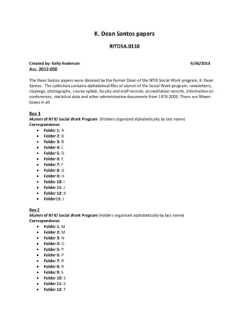
Project OverviewMoog Inc. is a corporation that designs and manufactures fluid control systems for variousindustries worldwide. The aviation branch of East Aurora, NY will be sponsoring a multidisciplinary senior project at RIT in which students will be developing a flight simulator. Thesimulator will be used for customer demonstrations to help sell Moog systems.Our software engineering team will be responsible for the visual content displayed in the flightsimulator. Our system will receive information from a system called the dSPACE controller andwill generate visual feedback in the form of a virtual cockpit window and instrument display.The dSPACE controller will be developed by Moog and acts as a façade between the hardwareinputs and our software package. The graphical output will be rendered using flight simulationsoftware that is already available. The instrumentation display will be created based off of theactual physical instruments found in the aircraft being converted in to a flight simulator.Context DiagramBasic Requirements3D Environment Curved screen, geometric correction Simulation Synchronization WarningInstrument Panel Air Speed IndicatorArtificial HorizonVertical Speed IndicatorTurn & Bank IndicatorHeading IndicatorAltimeter3
Stall WarningMultiple displays Two, mirrored instrument panels Multiple projectors for environmentARINC-429 compatibleCustomizable interfacesMultiple input methodsdSPACE flight dynamics modelUser StoryTaskAs a pilot I want to bewarned when the planeis about to stall so that itdoes not stall.StoryPointsAcceptanceCriteria1. Implement Medstall warninglight on flyingwall.3The stall warning Donelight is displayedwhen the plane iswithin a TBD thresholdofstalling.2.Receivestall warningfrom ARINC.2Done3.Updatewarning lightaccordingly.2Assigned1. Change on Lowscreen displayto low-g settingwhen out-ofsync.7The sync warning Donelight is displayedwhen the 3Denvironment andmotion table areout of sync.As a pilot I want a 1.Create Highseparateinstruments "flyingwall"display so that the aircraft model.environment display isnotobstructed.(originally estimated as7SP)3Alltheflight Doneinstrumentation isdisplayed on aseparate displaythantheenvironment.As a pilot I want to bewarned when the 3Denvironment is out ofsync with the motiontable so that I am awareof it being out of sync.BusinessValueStatus4
2. Set firstcameratopoint out at theenvironment.3Done3. Set secondcameratopoint at thewall.2Done4.Changingviews does notchangeinstrumentdisplay.3Done3Thesix Doneinstruments aredisplayedandupdate properly.2.Artificialhorizon dial.3Done3.HeadingIndicator.3Done4. Climb/sinkrate indicator.3Done5. Altimeter.3Done6.Turncoordinator.4Done7The3D Doneenvironmentreactsasexpected to thecockpit controls.As a pilot I want an 1. Indicated air Highinstrument display so speed gauge.that I don't crash theplane.As a pilot I want the 1. Implement Medcontrols in the cockpit to ARINC reader.controlthe3Dsimulationonthescreen so that I canexperiencesimulated5
flight.As a pilot I want thedisplay to refresh at atleast 60Hz so that myexperienceisnotlagging.2. ImplementARINC parser.5Done3.SetupFlightGearbuildenvironment inWindows.10Cancelled4.EmbedARINC FDMintoFlightGear.4Cancelled5. Send datafromARINCreadertoFlightGear viatheremoteinterface.3To rom item 8.4Assigned7.MakeARINC parserconfigurableusing either atutorial or UI.4Cancelled8. ImplementARINCtransmitter.3DoneMed3Thedisplay To verifyupdates at atleast 60 framesper second.6
As an administrator Iwant to be able to readflight data from a file sothat the source andformat can be changed.Low4The data is read Doneproperly and theformat can beeasily changed.As an administrator Iwant a tutorial forcreating/customizing thesix main instruments.1. Determine TBDthe differencebetweenupdatinggaugesthrough nasaland XML.2The customer is Doneabletounderstandthetutorial and createnew e1Theproject Doneposter has beensubmitted to beprinted.2. Create theproject posterconcept minaryproject poster(week 6).4Done4. Create finalproject poster(4/25).4To verify1.Create Hightechnicalreport outline(week 8).4Thetechnical To verifyreport is completeand submitted.AstheSoftware 1.Attend HighEngineering department project posterI would like a project meeting (4/3).poster to visualize theproject.AstheSoftwareEngineering departmentI would like a technicalreport to determine ifthestudentsmaygraduate.7
As a pilot I want the 3Denvironment display tobegeometricallycorrected to match thescreen shape.2. Draft thetechnicalreport (week10).7Assigned3. Write finaltechnicalreport (week11).4Assigned1.Install HighPixelWixsoftwareonthe .3To debug3. Perform alltests on on thescreen.display DonecorrectcurvedConstraintsThe project involved several constraints. From the beginning of the project, dSPACE wasrequired for the flight dynamics model. This meant that the flight simulator that was to bedeveloped would need to interface with dSPACE rather than using a built-in flight dynamicsmodel. Additionally, the software was required to be projected on a curved screen withgeometric correction. Early in the development process, FlightGear was added as a constraint.FlightGear was selected as the flight simulator that would be used because of its open-sourcenature. After much discussion, ARINC-429 was settled on to provide the connection betweenthe dSPACE computer and the FlightGear computer. ARINC-429 was chosen because it is usedin all modern aircraft to facilitate communication between the various subsystems. It will alsoallow Moog to connect additional equipment to the communications bus for testing anddemonstration purposes.Development ProcessThis project used a slightly modified scrum methodology. The schedule consisted of six twoweek sprints with a standup meeting twice a week and a sprint retrospective and planning onTuesdays bewteen sprints. The sponsor did not mandate or require approval of the process used.8
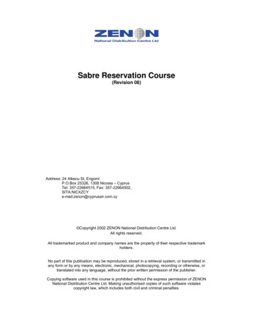
The sponsor was invited to all regularly scheduled meetings. Corey Engelman, being the electedteam leader, was appointed as the scrum master.Project Schedule: Planned and ActualThe final schedule is shown below. Sprint 1 was initially scheduled to start sooner, however itwas pushed back after encountering problems with initial setup work being done during Sprint 0.The other sprints were likewise pushed back to match. This made the Release Sprint shorter thaninitially intended. Further complications were encounter with Sprint 3 overlapping with thescheduled Winter/Spring break. Rather than end the sprint during the break, the sprint wasextended one week, and beginning Sprint 4 following the first regularly scheduled meeting.System DesignThis diagram shows our most significant design decision. The blue portion shows how we couldhave made the ARINC-429 software internal to FlightGear and recompiled FlightGear. In otherwords, FlightGear would access the hardware directly to update itself. The green portion showsour selected solution, in which we make the ARINC-429 software external to flight gear, andsend data to FlightGear.9
The deployment view below shows how our software interacts with the other pieces in ourhardware environment. The boxes with depth show physical separation, while other boxes showcomponents. The main point of this diagram is to show cockpit sensors sending signals to thedSPACE machine, where it outputs flight simulation data to our ARINC-429 library (a copy ofwhich is on both the dSPACE and FlightGear computers). The library then handles encodingdata and putting it on the hardware on the dSPACE machine. This sends it to the hardware on theFlightGear machine. The copy of the ARINC-429 library on the receive side then decodes all thedata coming off the hardware and sends it to FlightGear view sockets. Our XML dataspecification and configuration files are also on this machine and are read by FlightGear when itfirst runs.10
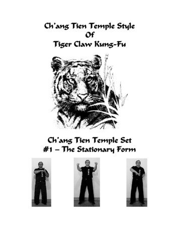
Process and Product MetricsThe team tracked story points throughout the development process. After initial planning duringSprint 0, there were 59 story points in total. At various points, additional points were added tothe backlog as additional requirements were added. Some requirements were eventuallycanceled, the points associated with that tasks are not included in the data shown here. Thenumber of story points assigned to each task was occasionally adjusted as the team began tosuspect a task would be easier or harder. As shown in the graph below, after a slow start, theteam began to average 13-14 story points per sprint, well above the ideal velocity of 8-9 storypoints per sprint.11
SprintPts. RemainingPoints CompleteIdeal PointsVelocitySprint 0 (S0)59059n/aSprint 1 (S1)59450.54Sprint 2 (S2)6011429.5Sprint 3 (S3)501533.51012
Sprint 4 (S4)63132510.8Sprint 5 (S5)412516.513.6Sprint 6 (S6)3011813.2Release Sprint (SR)030013.6Note: All sprints 14 days except SR which was 28 days. Final velocity has been adjusted accordingly.Product State at Time of DeliveryThe product is not complete due to several setbacks the entire Flying Tiger project experienced.Currently, the project consists of two key aspects: the FlightGear configuration, and the ARINClibrary. The configuration files include everything required to run FlightGear with the large 3Denvironment display and instrument panel. The ARINC library reads flight data from a file onone computer, transmits it across the ARINC bus, and passes the data to FlightGear, which thenrenders the flight accordingly. The data is read and transmitted at a rate of 64Hz.Additional work will be required to interface the transmitting side with the dSPACE flightdynamics model. There is a faulty ARINC cable which causes all the bits transmitted to beinverted, there is a workaround in-place to compensate for this issue. That workaround will needto be removed if a new ARINC cable is used. The workaround exists in theft channel monitor.cpp class. There is a line that says “if( is inverting bits() )”.The latitude and longitude labels used in the ARINC specification provide insufficient resolutionfor smoothly rendering a simulation. To circumvent this problem, the project includes supportfor custom ARINC labels which carry extended precision on top of the standard latitude andlongitude. The same is true for the roll and pitch.Project ReflectionOur team chose to use the Scrum framework to guide our project. We chose this path afterconcluding that the largest risks our team faced would be unknown requirements and an unclearvision of what the final product will be for the team. This worked very well for interceptingchanging and brand new requirements well into the project timeline. In the future, softwareengineer teams might be encouraged to teach their project sponsors about the development13
process they are using. Our sponsors were not aware of the Scrum framework and may havebecome frustrated with how our team operated. For example, a new requirement may have beenintroduced mid-sprint that the team was unable to address immediately. The agile methodologyrequires frequent communication with sponsors which is something the team had in thebeginning of the project but found to be lacking towards the conclusion. It would be better ifthere was better integration between the College of Engineering’s teams curriculum and ourdepartments.14
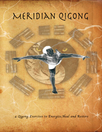
APPENDICESAppendix A – Gauge informationInterior Display – GaugesGauges in order: Brake light, gear light, stall warning light, airspeed indicator, artificialhorizon, altimeter, turn and bank indicator, directional gyro, and vertical speed indicatorThe interior display is created using XML files to define the placement, and movement of imagesthat are desired for display. If you are unfamiliar with XML, a good resource is available fromw3schools (http://www.w3schools.com/xml/). Our solution uses two dimensional images but it wiki.flightgear.org/Creating instruments for FG).The base XML file that defines the instrument panel is called ft-panel.xml). Instruments are added to the displaybetween the instruments tags. For example, we have included a Chronometer for aestheticpurposes: instrument include "././Instruments/clock.xml" 15
name Chronometer /name x 177 /x y 316 /y w 74 /w h 74 /h /instrument The include attribute points to the location of the gauge’s XML file. The x and y tags definewhere on the display the instrument is located and the w and h tags define how wide and high theinstrument is. You can edit the XML file while running the simulation to see how removingdifferent instruments affects the display in real-time. Use Shift-F3 to refresh the instrument panelto see how editing the XML file operates.The scope of the Flying Tiger project included creating the instruments highlighted below basedon existing ones available in the software. There are numerous instruments available that can beadded to the interior display that have already been created and are available with everyFlightGear install (FlightGear\data\Aircraft\Instruments). Each instrument has image ghtGear\data\Aircraft\Instruments\Textures).Each gauge has the same XML layout. Each image that makes up the instrument is added as a layer ordered from bottom to top. Each layer is added between the layers tag. Each layerhas the following tags: name - Name of the instrument texture - Adds image of this layero path - Location of the imageo x1 , y1 , x2 , y2 - Coordinate location of where to capture the image as apercentage where 1.0 100%. x1 0.0 /x1 y1 0.0 /y1 x2 1.0 /x2 y2 1.0 /y2 The configuration above grabs all of the texture transformations - All animation definitions are included between this tago transformation - Adds an animation type - Type of animation. The documentation of animations is out of date tgear.org/Howto: Animate models#Animation types) property - Location in the property tree that defines how the layer will beoriented (http://wiki.flightgear.org/Property Tree) min , max , scale - Set limits on animationThe gauges included in the Foxtrot Tango solution are detailed below as they may serve as abase model for instruments Moog may wish to include in their final product.16
Altimeteraltimeter.xmlThe altimeter gauge is used to measure the altitude of the aircraft in feet. Its layers include: Subscale - altimeter-subscale.pngo /instrumentation/altimeter/setting-inhgo Rotates for precise altitude measurementsGauge face – altimeter-bg.pngo No animation. Base image.Short needle – arrow.pngo /instrumentation/altimeter/indicated-altitude-fto Rotates to indicate altitude in thousands of feetLong needle – arrow.pngo /instrumentation/altimeter/indicated-altitude-fto Rotates to indicate altitude in hundreds of feetButton – button.pngo No animation. Base image.Glare shield – glare-shield.rgbo No animation. Base image.Airspeed Indicatorasi.xmlThe airspeed indicator displays the airspeed of the aircraft in knots. Its layers include: Gauge face – asi-bg.pngo No animation. Base image.Needle 1 – arrow.pngo [TODO] propertyo Rotates to indicate speed in thousands of knotsNeedle 0 – arrow.p
ARINC FDM into FlightGear. 4 Cancelled 5. Send data from ARINC reader to FlightGear via the remote interface. 3 To verify 6. Interface dSPACE computer w/ ARINC transmitter from item 8. 4 Assigned 7. Make ARINC parser configurable using either a tutorial or UI. 4 Cancelle