Transcription
ICRAT 2020Morphing STARs vs drones and weather in TMAHenrik HardellAnastasia Lemetti, Tatiana Polishchuk and Valentin PolishchukCommunications and Transport Systems, ITN,Linköping University, Norrköping, SwedenProcedure Design Unit, Luftfartsverket (LFV),Norrköping, SwedenCommunications and Transport Systems, ITN,Linköping University, Norrköping, SwedenVishwanath BulusuEnric RoyoCrown Consulting Inc.,Moffett Field, California, USACal Unmanned Lab, University of California,Berkeley, California, USAThe School of Industrial, Aerospace andAudiovisual Engineering of Terrassa (ESEIAAT),TU Barcelona, SpainAbstract—We present an optimization framework for computing STARs that slowly change over time, while always avoiding aset of moving obstacles in TMA. The framework is applied to twotypes of obstacles: a drone intruder and hazardous weather. Wedemonstrate the output of our algorithms on synthesized droneintrusion incidents and real storm cells in Stockholm Arlandaterminal area.Keywords—TMA route design; ATM and UTM; WeatheravoidanceI. I NTRODUCTIONDrones interfering with aircraft on approach are reportedwith alarming frequency. Such interference poses serious riskto development of the emerging drone industry, as it negativelyimpacts public acceptance of UAV (Unmanned Aerial Vehicle)operations. Economic damage and passenger discomfort is especially aggravated when drone sighting leads to cancellationof flights through the whole terminal airspace and prolongedfreeze of airport operations.We are thus motivated to consider closing only that partof the airspace where the drone is physically present andrecompute the arrival tree so that the aircraft safely land,avoiding the drone-affected part. The challenge is that thedrone is moving, implying that the drone-impacted area is amoving obstacle. In addition, since the drone may be spottedonly once, its uncertainty region grows, meaning that the droneobstacle not only moves but also may expand with time. Thismakes the drone deconfliction similar to weather avoidancei.e. escaping both kinds of obstacles fits into the same abstractmodel.In this paper we extend the optimization framework from [1]for constructing operationally feasible obstacle-avoiding staticstandard arrival routes (STAR), to handle obstacles changingThis research is supported by the SESAR Joint Undertaking under the European Union’s Horizon 2020 research and innovation programme under grantagreement No 783287. It is also partially supported by Transportstyrelsen,Trafikverket and in-kind participation of LFV.with time and to output morphing STARs that never changeabruptly (so controllers and pilots may easily see how theSTARs evolve over time). Our mathematical model for themorphing STARs works with any type of abstract obstacles.To illustrate it, we present experimental results of applicationof the morphing STARs to drone deconfliction and to weatheravoidance in the terminal maneuvering area (TMA) of Stockholm Arlanda airport. While the drone intrusion scenario issynthesized, for the weather data we took a real storm.The paper is organized as follows. The remainder of thissection reviews related work. Section II formalizes the modeland Section III casts our problem as an integer linear program(IP). In Section IV we apply the IP to drone and weatheravoidance in Stockholm Arlanda TMA. Section V concludesthe paper.A. Related workTechnologies proposed to detect, track and shoot downdrones include radars, cameras, eagles [2], counter-droneUAVs [3] and jamming [4] – a comprehensive survey canbe found, e.g., in the thesis [5]. Still, a commonly acceptedand implementable solution has yet to be developed (e.g.,the Blue Ribbon Task Force report [6] on UAS mitigation atairports unfortunately offers ”disconcerting” [7] conclusions).The governments are not ready to deploy the offered solutionsprimarily because technologies for multi-aviation airspacemust first go through the cycle of validation and certification.Furthermore, the actual handling of the drone intruder is upto the police, who would appreciate information sharing bothwith ATM and UTM (or the future combined system). It isalso necessary to correlate the detected drone with what UTMknows, in order to distinguish between a lost drone of a goodcitizen and a malicious intent to fly unnoticed.Impact of deep convection and thunderstorms is also subjectto ongoing research, e.g. Steiner et al. [8], [9] and Songet al. [10] investigated its implication both on the en-route
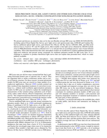
ICRAT 2020flow management and for terminal area applications. Kleinet al. [11] used a high-level airport model to quantify theimpact of weather forecast uncertainty on delay costs. Steineret al. [12] discuss the crucial effect of accurate forecasts ofhigh-impact winter weather for efficient management of airportand airline capacity and highlight the need of data sharingand integrated decision making between stakeholders. Recentworks [13], [14] confirmed the relevance and emphasizedthe importance of quantification and analysis of the weatherimpact on airport operation. In addition, we refer the reader topublications by TBO-MET project [15] for a comprehensiveaccount of weather impact on ATM.Unlike the drone threats, avoiding hazardous weather has along history in ATM. In particular, the idea of our morphingSTARs is inspired by the enroute flexible flow corridors [16]that change shape as the weather obstacles move. However,the TMA setting and the solution techniques in this paper arecompletely different from [16]. Our solution is also completelydifferent from the ones in [17], [18], [19], [20], [21], [22] inwhich the traffic is merged to a point, representing the runway,or to a circle around the runway. In this paper, the runway isa directed segment, and part of the challenge is to align thearrival flow with the runway.II. M ODELING AND PROBLEM FORMULATIONFollowing the setup in [1], the TMA is modelled by arectangle (Fig. 1). A square grid V of points is laid downinside the rectangle, and every grid point is connected to its 8immediate neighbors North, East, South, West, NE, SE, SW,and NW (these connections may be used by the STAR tolink the TMA entry points to the runway). The grid points V ,together with the connections (denoted by E) form the graphG (V, E) which we will search for the paths. The graph isbidirected: for any two vertices i, j V , both directed edgesij and ji belong to E. (We use the notation ij and i, j for theedge interchangeably.)The runway is in the middle of the square, with the landingdirection pointing South (RWY 19L). The airspace has fourentry points: one on each side of the TMA. Such modelingis done only for simplicity, as our techniques work witharbitrarily shaped airspace (e.g., one way of handling anarbitrary-shape airspace may be to ”carve it out” from thesquare by declaring as obstacles the parts of the square whichdo not belong to the airspace shape), any number of entrypoints (without restriction on their locations) and runwaylocated anywhere. Basically, the model represents a genericTMA with entries from different directions and a runwaysomewhere inside.In addition to the TMA with its entry points and the runway,the input to our problem consists of a set of moving obstacles:for any time step t [1, . . . , T ] within a given planninghorizon T , we are given a set of polygons that affect the routes.In a pre-processing step, for every t we determine the subsetOt E of edges of G that overlap with the obstacles.Weights of the edges are the last input. We use ij to denotethe weight assigned to edge ij E. In the weather avoidanceFig. 1: Left: The STAR (blue) avoiding the obstacles (red).Right: A grid vertex is connected to the 8 neighbors. The turnconstraint means that if edge e is used by a STAR, then noother edge in the blue region Γe (i.e,, an edge forming anangle less then γ with e) can be used in the STAR.application the weights indicate the severity of the convectiveweather. For the drone deconfliction the weights of edgesoutside the obstacles are just the lengths of the edges, while theedges inside the obstacles get infinite weight: travel throughthe obstacle is forbidden. Note the important difference—bothalgorithmic and conceptual—between weather avoidance anddrone deconfliction: while in the former application a feasiblesolution always exists, in the latter, the obstacles are hardconstraints that may not be intersected by the paths, whichmeans that a problem instance may be infeasible.As the output of our problem, we seek a sequence(T1 , . . . , TT ) of arrival trees (STARs) in G, that merge theentries to the runway. That is, for every t [1, . . . , T ], thetree Tt should have the entries as leaves and the runway asthe root (contrary to the common convention, we assume thatthe edges of the arborescence are directed from leaves toroot). The STARs should be disjoint from the obstacles – i.e.,identifying a tree with its edges, we require Tt Ot .Operational feasibility of the STARs is ensured by requiringthat they satisfy the requirements outlined in [1]: at most tworoutes merging at a point (translating to the requirement thatevery vertex of the tree must have in-degree less than or equalto 2), and the turn constraints (no sharp change of direction atany node). Last but not least, we add the new requirement thatthe STARs should change ”slowly”; we model it by requiringthat Tt 1 and Tt should differ by at most U edges, where Uis a parameter given in the input: Tt 1 Tt U (where denotes the symmetric difference).Similarly to [1], we consider two objectives for any tree:minimizing the total weight of the entry-to-runway paths inthe tree and the total weight of all edges in the tree (the twoobjectives are different because some edges are used by pathsfrom more than one entry; see [1] for an in-depth study); wecall the two objective functions the path length and the treeweight respectively. The objective function in our IP is thesum, over all timesteps, of a linear combination of the path
ICRAT 2020length and tree weight (see Equation (11) below).III. T HE INTEGER PROGRAMWe formulate our problem as an integer program (IP). OurIP is a modification and extension of the IP from [1] for findingone, static STAR: we add the time dimension to allow theSTAR to morph, and add constraints that assure consistencybetween the consecutive trees.Variables: Our main binary decision variables xe,t indicate whether the edge e E participates in the arrival tree attime t [1, . . . , T ] (i.e., whether e Tt ). We also have integerflow variables fe,t that give the flow on edge e (i, j) (i.e.,the flow from i to j) at time t; the flow is the number of entry–runway paths that go through the edge, or in other words, thenumber of entry points that connect to the runway using theedge.Tree constraints: The following constraints ensure that atany time t, the edges with positive decision variables (xe,t 1) form a tree that connects the entry points to the runway.We use P to denote the set of the entry points and r to denotethe runway. Both the entry points and the runway are assumedto be vertices of G, i.e., (P r) V . P i rXXfki,t fij,t 1 i P k:(k,i) Ej:(i,j) E0 i V \ {P r}(1) t [1, . . . , T ]xe,t fe,tQ e E, t [1, . . . , T ] (2)xki,t 2 i V \ {P r}, t [1, . . . , T ](3)xij,t 1 i V \ {P r}, t [1, . . . , T ](4)xkr,t 1 t [1, . . . , T ](5)xij,t 1 i P, t [1, . . . , T ](6)k:(k,i) EXXxe0 ,t ce e E, t [1, . . . , T ](7)e0 ΓeBy Equation (7) we can either use edge xe,t (which sets theleft-hand side to ce , the upper bound provided by the righthand side, and prohibits the use of any edge in Γe ), or wemay use any subset of the edges in Γe .Consistency between trees of consecutive timesteps:Recall that we measure consistency in terms of the number ofdifferent edges used in the trees, and we want to assure thatthe trees do not change too much from a timestep to the nexttimestep. To implement this we define a binary variable ye,tthat equals xe,t xe,t 1 (Equations (8)-(9)), and then limit thenumber of differing edges in Equation (10) by parameter U :ye,t xe,t xe,t 1 e E, t [1, . . . , T 1](8)ye,t xe,t 1 xe,t e E, t [1, . . . , T 1]Xye,t U t [1, . . . , T 1](9)(10)Objective function: Since the flow variable fe,t representsthe total number of entry–runway paths that go through edgee at time t, the path length, i.e.,P the total length of all entry-torunwaypathsinthetreeTiste E e,t fe,t . The tree weight isPe E e,t xe,t . Our objective function is a linear combinationof the path length and tree weight, summed over the planninghorizon:X XX X(1 β) e,t fe,t β e,t xe,tt [1,.,T ] e Et [1,.,T ] e E(11)We used β .1, prioritizing path length (to make sure xe,t 0 for edges with 0 flow, β must be strictly greater than 0).Note that our IP is run only once, altogether for allt [1, . . . , T ] (i.e., we do not run a separate IP for eachtimestep t).IV. E XPERIMENTAL RESULTSj:(i,j) EXk:(k,r) EXce xe,t e EHere Q is a large number (e.g., Q P ). Equation (1) ensuresthat a flow of P reaches the runway r, a flow of 1 leavesevery entry point, and in all other vertices of the graph theflow is conserved. Equation (2) enforces edges with a positiveflow to participate in the STAR, and since xe,t are part ofthe objective function (see Equation (11) below), edges with0 flow will have xe,t 0.Degree constraints: Equations (1)-(2) are standard IPconstraints for a MinCostFlow Steiner tree formulation. Thefollowing constraints ensure that the requirements put on thedegrees of the tree nodes are satisfied:Xvertices is given by Equation (3), and the maximum outdegreeof 1 – by Equation (4).Turn angle constraints: Next, we ensure that for eachedge e (i, j) used in any arrival tree, all outgoing edges atj form an angle of at least γ with e (see Fig. 1, right). LetΓe be the set of all outgoing edges from j that form an angle γ with e, i.e., Γe {(j, k) : 6 ijk γ, (j, k) E}, and letce Γe . We add the following constraint:j:(i,j) EEquation (5) ensures that the runway r has one in-goingedge, Equation (6) makes sure that each entry point has oneoutgoing edge. The maximum indegree of 2 for all otherThis section presents application of the IP from Section IIIto two types of events in Stockholm Arlanda TMA: droneintrusion and inclement weather. We covered the TMA with a66nmi x 90nmi rectangle and laid out an 11x15 grid G withdistance 6nmi between the gridpoints (i.e., a grid pixel hasside length of 6nmi). The grid edges outside the TMA weredeclared as permanent obstacles, to make sure the STARs staywithin the TMA.For the drone scenario, we generate the initial point p wherethe drone was detected at time t 1 so that the projected
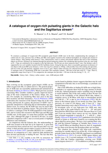
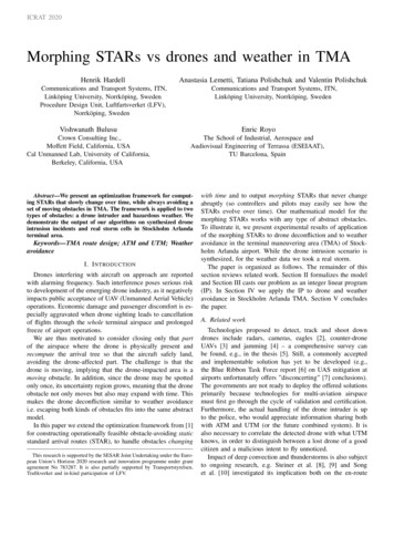
ICRAT 2020PO1O2O3Fig. 2: If a drone is detected in the pixel P , during one timestepit will stay in P or a neighboring pixel. The growth of thedrone obstacle at timesteps 2 and 3 is shown with the lightblueand red.drone-impacted area does not reach the runway during thetime horizon (otherwise no feasible solution can be found).Since drones in airport vicinity are often simply spotted bynaked eye, without the ability to give an accurate estimate ofits position, we add an uncertainty region around the intrudersighting. Specifically, let P be the pixel containing p. Weassume that the error in determining the drone position is3nmi (half the pixel size); then at time t 1 when the droneis detected, it can be anywhere within P . We declare the 3x3square of pixels around P as the obstacles O1 (Fig. 2). We setthe time unit (the interval between t and t 1, or equivalently,the time between STAR updates) to 6nmi/v where v is (anupper bound on) the speed of the drone. Put differently, thetime unit is chosen so that the drone may cover maximum6nmi (the side of a pixel) in one timestep. This way, by theend of the first time unit (i.e., by the time t 2), the droneis guaranteed to stay within O1 .The closed airspace (i.e., the uncertainty region withinwhich the drone may potentially be found) expands with time:the obstacles Ot 1 are obtained by adding to Ot the belt ofpixels that share boundary with Ot (refer to Fig. 2). This is asafe growth: by induction on t, the drone cannot get outsideOt by the end of t-th time interval. We are thus always onestep ahead of the drone, conservatively closing parts of theairspace before the drone can possibly reach them.Overall, during an intrusion incident, the authorities wouldhave to supply our framework with estimations or best guessesof two drone characteristics – the maximum speed v and themaximum lifetime . The latter may be based on the batterylife, time to detect the drone and mitigate the intrusion, etc.(see [5, Section 3.2] for a discussion). We translate intothe time horizon T d /(6nmi/v)e expressed as the numberof timesteps. Our IP then outputs the sequence (T1 , . . . , TT )of the necessary number T of STARs, updated with thecorresponding frequency – the duration of the time unit. Ifan update of the drone location arrives (e.g., if the drone istracked), the obstacles can be recomputed accordingly. Wemodel the situation when the drone is seen only once.For our experiments we chose 2 scenarios: a very gooddrone (representing the most impactful case) and an averagedrone. If a detection system or another source gives anindication of what kind of drone the airport is dealing with,there is no need to hedge against the worst case. We chosethe values for v and based on Google answer boxes for”drone speed” and ”how long a drone flies”, which inform that”Drones from leaders in the drone industry have a maximumspeed between 50-70mph” [23] and that ”A drone can flyfor about 15-30 minutes on average for most of the populardrones available” [24]. We therefore took v 72nmi/h and 30min for the advanced drone scenario. Note that speedand endurance are conflicting objectives, so the high speedand long flight time may not necessarily co-exist in a singledrone model, meaning that ours is a conservative estimate ofthe intruder performance (exploring the full Pareto frontierof drone speed/fligthtime is outside our scope). The chosenv implies that the drone crosses the 6nmi pixel in 5min,which becomes the time unit for our STAR update; the 30minhorizon thus consists of T 6 timesteps. For the ”average”drone we halved the speed (leading to the timestep of 10min)and assumed lifespan 20min, translating to the need tocommute just two trees (T 2).Finally, the STAR ”smoothness” parameter U was set to10. Because a STAR consists of approximately 50 edges, thismeans that at most 20% of the tree is allowed to change fromtimestep to timestep. While in principle it allows half of theedges to change after 5 steps, such drastic overall changes werenever observed in our experiments. This is likely due to ourobjective of minimizing the total length of all STARs. In otherwords, trying to stay short, the STARs ”hug” the obstacles,locally avoiding them, but not changing much globally.We solve the IP using AMPL and Gurobi optimizationsoftware installed on a very powerful Tetralith server [25],utilizing the Intel HNS2600BPB computer nodes with 32CPU cores, 384 GiB, provided by the Swedish NationalInfrastructure for Computing (SNIC). One problem instancetook 10 minutes to solve.Figure 3 covers both scenarios: the first two subfigures (forT 1 and T 2) correspond to the slow drone scenario,and all the six trees illustrate the worst-case drone expansionscenario. The STARs computed by our algorithms avoid theobstacles, staying close to them – this is due to the objective ofminimizing the length of the trees. Note that when the obstaclecovers the entry point, the tree follows the TMA boundaryuntil the path can enter the TMA – in practice, the entry maybe moved there.We now describe our experiments with the weather. Since aweather event is evolving more slowly than a drone intrusionincident, we use hourly weather updates to define the obstaclesOt at every hour t and update the STARs every hour duringa time horizon of T 5 hours.We used a Convective Available Potential Energy (CAPE)metric, which is an indicator of the instability of the atmosphere and can be used to assess the potential for thedevelopment of convection, which can lead to heavy rainfall,thunderstorms and other severe weather. CAPE is the energya parcel of air has for upward motion, measured in joulesper kilogram of air (J/kg). Observed values in thunderstorm
ICRAT 2020(a) T 1(b) T 2(c) T 3(d) T 4(e) T 5(f) T 6Fig. 3: The drone-affected area is dark red. The STARs for every 5min within a 30-min time horizon are black.environments often may exceed 1000 J/kg. Note, that ourmethod is universal, and CAPE can be replaced with anyother indicator of the convective activity, or other weatherphenomena evolving in time horizon.We took the historical weather data from the ECMWFERA5 reanalysis dataset provided via the C3S Data Store [26].ERA5 provides estimates for each hour of the day and thedata cover the Earth on a 0.25 grid. July 29, 2018 waschosen as the highest values of CAPE were recorded onthis day (above 1000 J/kg). We took CAPE values for the59 61 N, 17 19 E grid as it covers the StockholmArlanda TMA area.The weather cells are given weight based on the severity,and paths with low weight (weather exposure) were sought.Weights to all possible links are assigned based on the locationof the weather cells, and we assign higher weights to the linksimpacted by the higher activity weather. Since the weathercells granularity is not the same as the grid granularity, weassign weights of the nearest weather point to all links inthe grid cell. Also, when one link is close to more thanone weather cell, the highest weight of all close-by cells isassigned. In Figure 4 the weather-impacted links are coloredas follows: A CAPE value below 800 is given a weight of 1and is not shown in the figures (we assume low impact of theconnective weather associated with these values). Light yellowcorresponds to a CAPE value of 800-899, yellow correspondsto a CAPE value of 900-999, orange corresponds to a CAPEvalue of 1000-1099, red corresponds to a CAPE value of 11001199 and dark red corresponds to a CAPE value above 1200.Figure 4 shows how the high activity storm cells are beingavoided in most cases.First, we set U 5 in this experiment. Given such a lowflexibility in the number of links the trees can be different in,and having all the trees optimized together in one program,the resulting routes are not always passing through the cellswith the lowest weather activity (e.g. the route from the southentry in Figure 4 (b)).With U 20 (Figure 5), the difference between the treesis more noticeable. The resulting paths are better adjusted tothe current weather conditions (e.g. for T 2 in Figure 5 (b),the route from the south entry is now passing through thecells with the lowest weather activity). Another example is therightmost STAR for T 6, where in the first case (U 5,Figure 4 (f)) the path from the south entry is passing throughsome weather-impacted regions, while in the second case (U 20, Figure 5 (f)) safely avoids them.This demonstrates the trade-off between the total path lengthand the consistency between the trees objectives. We presentthe total path lengths for the resulting trees for differentvalues of the STAR ”smoothness” parameter U in Table I andvisualize the Pareto-optimal solutions in Figure 6. High valuesof the total path lengths are resulting from the high weightsof the tree edges belonging to the weather-impaired regions.TABLE I: Total weighted path lengths for the trees withdifferent STAR ”smoothness” parameter UU5102030T 187413736T 21026878582537T 32019197118341729T 44106386234343433T 59300935094009300T 65321353736Total17070162371532415071V. C ONCLUSION AND FUTURE WORKDrone interference on approach is a well recognized issueand brainstorming on its solution is ongoing (see e.g., 4 waysfor drone threat reduction from The Hill [27]). This paperadds a thought on a possible mitigation strategy by pure ATMmeans, without involving any interception equipment. Indeed,shooting into a congested TMA, even with high-precisiondrone-aimed cannons would likely be an unpopular solution.On the contrary, applying soft measures, like the one proposedin this paper, may be hardly noticeable by the passengers(other than the potential delays due to rerouting) and will allowthe authorities to avoid bad publicity. Future work may lookmore closely at the drone impact at different heights alongthe STAR, as the small drones would not be able to reach thealtitudes at which aircraft usually arrive at the entry fix.On the technical side, our solution entails extending anIP-based optimization framework for obstacle-avoiding STARgeneration [1] to the case of moving obstacles. The extendedframework was applied to two types of TMA obstacles –drones and convective weather. Our algorithms output slowly
ICRAT 2020(a) T 1(b) T 2(c) T 3(d) T 4(e) T 5(f) T 6Fig. 4: Optimized STARs with weighted links based on severity of the weather, for six different time steps T for U 5.CAPE intensity is illustrated by the color of the links. The darker colors, the higher CAPE values.(a) T 1(b) T 2(c) T 3(d) T 4(e) T 5(f) T 6Fig. 5: Optimized STARs with weighted links based on severity of the weather, for six different time steps T for U 20.CAPE intensity is illustrated by the color of the links. The darker colors, the higher CAPE values.information becomes available. Handling the multitude ofsuch parameters may quickly become infeasible for a humancontroller, implying that our methods may rather be applicableat a higher level of ATS automation (e.g., in a to-be-designedmore dynamic UAM airspace) where the information about themorphing paths will be easily uplinked to the FMS. At thispoint even the terminology ”STAR” may become obsolete, asthe used routes are not the standard published ones.Fig. 6: Pareto optimal solutions for two objectives: STAR”smoothness” and the total route lengths over all STARs.morphing STARs that avoid the obstacles and do not changetoo fast over time.While for the proof-of-concept we modeled the droneobstacle as a growing square, the drone-affected area may bemore accurately modeled by a growing disk. Our approach isdirectly extendable to working with disks or, in fact, arbitrarilyshaped closed off areas. For instance, in presence of winds,an elongated shape of possible drone locations may be moreappropriate. The main idea is that the drone obstacle issimply a set of parameters, which may be adapted as newOne important aspect ignored by our model is keeping theaircraft separated while the STAR is morphing. In [28], thealgorithm from [1] was modified to ensure the separationalong a static STAR. The modification may be potentiallycombined with the extension in this paper to enforce separationon the morphing STAR. Of course in practice, during a droneinterference incident, the situation will be given extra attentionfrom the TMA controllers who will vector the aircraft ifnecessary for the separation. Keeping the aircraft separatedduring a weather event is, on the contrary, a nominal situation.In addition to the constraints on the STAR considered in thispaper, [1] also took into account STAR–SID deconfliction byvertical separation. It is straightforward to add such separationto our constraints. We did not do it in order to focus on aminimal non-trivial problem in this paper, highlighting thenovelty (avoiding moving obstacles); a detailed study of theSTAR–SID interaction was done in [1]. Yet again, duringthe drone intrusion departing traffic might be held on the
ICRAT 2020ground, while in the weather avoidance scenario, taking SIDinto account may be included into the optimization framework.A standard assumption in all research on STAR design isthat the runway configuration is specified, i.e., the landingrunway is given in the input. It may be interesting to lift thisassumption and extend our framework by allowing to changethe configuration and land (possibly, part of) the traffic onanother runway. This may be particularly useful if landing allaircraft to the single, given runway is infeasible.Given the huge impact of weather on ATM, it may beworth exploring how weather data granularity influences thearrival routes. For that, one could either take several weatherdata sources, or simply coarsen the given weather data byblurring it (i.e., considering it on a coarser grid). Then, forthe STARs computed using the different-granularity weather,several performance indicators (PIs) may be evaluated. ThePIs may be compared both among the STARs and versus thereal operational flights.The first tree T1 in our STAR sequence (T1 , . . . , TT ) isoutput by our IP. Alternatively, one could take some existingtree T0 as the input and require that also the first tree T1 doesnot differ too much from T1 : T1 T0 U . This would be astraightforward addition to our framework.ACKNOWLEDGMENTWe thank Helena Samsioe (Glonhe), Attila Takacs (Ericsson), Dr. Parimal Kopardekar (NASA) and Billy Josefsson(LFV) for helpful discussions. We acknowledge the anonymous reviewers for their valuable comments imoroving thepresentation of the paper.R EFERENCES[1] T. Andersson Granberg, T. Polishchuk, V. Polishchuk, and C. Schmidt,“Automatic design of aircraft arrival routes with limited turning angle,”in ATMOS 2016, August 25, 2016, Aarhus, Denmark, vol. 54, 2016, pp.9–1.[2] A. Toor, “Holland’s drone-hunting eagles are ready to fly,” 2016, s-drone-hunting-eagles,last accessed 14.02.2020.[3] Fortem Technologies, “Ultimate c-uas interceptor,” 2020, https://fortemtech.com/products/dronehunter/, last accessed 14.02.2020.[4] Rafael, “Drone dome – c-ua
with ATM and UTM (or the future combined system). It is also necessary to correlate the detected drone with what UTM knows, in order to distinguish between a lost drone of a good citizen and a malicious intent to fly unnoticed. Impact of deep convection and thunderstorms is also subject to ongoing research, e.g. Steiner et al. [8], [9] and Song