Transcription
45222 AppA 10/5/2009 9:46:25 Page 1Microsoft Visio Professional is a powerful database design and modeling tool.The Visio software has so many features that it is impossible to demonstrate allof them in this short tutorial. However, you will learn how to:쐍 Start Visio Professional.쐍 Select the Crow’s Foot entity relationship diagram (ERD) option.쐍 Create the entities and define their components.쐍 Create the relationships between the entities and define the nature of those relationships.쐍 Edit the Crow’s Foot ERDs.쐍 Insert text into the design grid and format the text.Once you have learned how to create a Visio Crow’s Foot ERD, you will be sufficientlyfamiliar with the basic Visio Professional software features to experiment on your own withother modeling and diagramming options. You will also learn how to insert text into thePreviewVisio diagram to document features you consider especially important or to simply providean explanation of some segment of the ERD.Note:The screens and instructions in this tutorial are for Microsoft Visio Professional 2007.If you are using an earlier version of Visio, your screen will vary slightly. If you are using Visio2007 and you wish to save files that are also usable in Visio 2003, you must use the File, SaveAs menu choice and choose to save the file in Visio 2003 format.AA P P E N D I XDESIGNING DATABASES WITH VISIOPROFESSIONAL: A TUTORIAL
45222 AppA 10/9/2009 9:49:30 Page 2A-2A P P E N D I XAA.1 STARTING VISIO PROFESSIONALThe typical Visio Professional software installation lets you select Visio through the Start, (All) Programs,Microsoft Office Visio sequence. If Microsoft Office has also been installed, then Visio may be found underMicrosoft Office in the Start menu. After the Visio software has been activated, click the Software and Databaseoption to match the screen shown in Figure A.1. (Previously created Visio files show up in the Recent Documentsheader on the right side of the screen.)FIGUREThe Visio Professional opening screenA.1As you examine Figure A.1, note the cursor over the arrow button next to the question mark at the upper-right cornerof the screen. The cursor shows the various toolbar options that you may select. Although you can customize yourtoolbar through this selection, for this tutorial, keep the toolbar at its default view to make sure that you will see thestandard Visio screens.With the Software and Database selection shown in Figure A.1, select the Database Model Diagram object.Note that your selection results in a gray shadow around the object. Also note that the cursor changes to a hand witha pointing finger, as shown in Figure A.2. In addition, you will see the Database Modeling Template description in theleft side of your screen.
45222 AppA 10/1/2009 8:17:13 Page 3D E S I G N I N GFIGURED A T A B A S E SW I T HV I S I OP R O F E S S I O N A L :ATU T O R I A LThe database model object selectionA.2Click the Create button shown in Figure A.2 to produce the screen shown in Figure A.3. Because the preference hereis for a larger grid than the one shown in Figure A.3, start by clicking the size selection (zoom) list box located on thebutton bar at the top of the screen. Click the down arrow to generate the list of size options, shown as percentages.Figure A.3 shows that the 100% option has been selected. When you click the 100% selection, the grid expands tofill the screen.By selecting the Visio Professional database option and its drawing board, you have completed the preliminary workrequired to create ERDs. You are now ready to draw the ERDs on the drawing board. You will use the Crow’s Footoption, the same one used to create all of the ERDs in this text.A-3
45222 AppA 10/1/2009 8:17:14 Page 4A-4A P P E N D I XFIGUREAThe drawing board size optionA.3A.2 SETTING THE STAGE FOR CREATING A CROW’S FOOT ERDTo select the Crow’s Foot option, select the Database, Options, Documentѧ sequence shown in Figure A.4.(Note that the drawing grid has expanded in response to the 100% selection shown in Figure A.3.)When you click the Documentѧ option shown in Figure A.4, you will see the Database Document Optionswindow in Figure A.5. The default selection is the General tab shown in Figure A.5. Note that the default selectionsin the General tab are Relational and Physical names. Leave the default options shown in Figure A.5. (The blackdots inside the white circles, known as radio buttons, indicate that the option was selected.) If your screen does notshow these selections, click their radio buttons to place the black dot inside the white circle.Move the cursor to the Relationship tab shown in Figure A.5. Click to select it to produce the screen shown inFigure A.6. Make sure that a check mark is in the check box next to the Crow’s feet option to indicate that thisoption was selected. If there is no check mark, click this check box to select this option. (If a check box is “grayed out,”it cannot be changed. For example, at this point, the check boxes under the Show verb phrase option cannot bechanged because the option has not been selected.)
45222 AppA 10/2/2009 11:56:22 Page 5D E S I G N I N GFIGURED A T A B A S E SW I T HV I S I OP R O F E S S I O N A L :ATU T O R I A LThe Database/Options/Document selectionA.4FIGUREThe Database Document Options windowA.5Examine Figure A.6 and note that the relationship name to be displayed has not yet been indicated; therefore, neitherhas how the names are to be displayed. You will return to this dialog box later to see the effect of these selections andto demonstrate that you can edit the displays when you are working on them.A-5
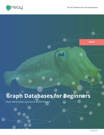
45222 AppA 10/2/2009 11:57:5 Page 6A-6A P P E N D I XFIGUREAThe Database Document Options, Relationship tabA.6Next, select the Table tab in the Database Document Options dialog box, as shown in Figure A.7. Make sure that thecheck boxes are marked as shown here.FIGUREThe Database Document Options, Table tabA.7Click the OK button shown in Figure A.7 to begin creating Crow’s Foot ERDs.A.2.1 The Business RulesTo illustrate the development of the Visio Professional’s Crow’s ERD, you will create a simple design based on thefollowing business rules:1.A course can generate many classes.2.Each class is generated by a course.3.A course may or may not generate a class.
45222 AppA 10/2/2009 11:57:5 Page 7D E S I G N I N GD A T A B A S E SW I T HV I S I OP R O F E S S I O N A L :ATU T O R I A LNote that a class has been defined as a section of a course. That definition reflects the real world’s use of the labelsclass and course. Students have a class schedule rather than a section schedule. The catalog that lists all of the coursesoffered by a department is called a course catalog. Some courses are not taught each semester, so they may notgenerate a class during any given semester. In fact, some courses may be taught only when there is sufficient studentdemand.A.3 CREATING AN ENTITYNow that you have some idea of the proposed design components, let’s create the first entity for the design. Click theEntity object shown in Figure A.8. (It is circled in the figure.) Drag the Entity object to the grid and then drop it. Thataction will produce the Table1 object shown in the grid in Figure A.8. (The 1 in the Table1 label indicates that thisis the first entity object to be placed on the grid.) Note that the entity object is shown as a table. That’s because theentity object is represented by a conceptual table.FIGUREPlacing the entity object in the gridA.8As you examine Figure A.8, note that the small square selection handles around the Table1 object perimeter indicatethat the Table1 object has been selected. You can deselect the object by clicking an empty portion of the grid. If theTable1 object has not been selected, click it to select it.A.3.1 The Database Properties WindowIf the Table1 object has been selected as shown in Figure A.8, you will see the default Database Propertieswindow at the bottom of the screen. (You will see later in this section that the window’s location and format mayA-7
45222 AppA 10/2/2009 9:15:19 Page 8A-8A P P E N D I XAbe changed to become the new default. However, you will start by using the standard default window shown inFigure A.8.)As you examine the Database Properties window in Figure A.8, note the selection of the Definition option inthe Categories: listing. (To select any option in the list, click it. The selection is indicated by the arrow to the left ofthe option. In this case, the arrow appears next to the Definition option.) At this point, the default Table1 labelshows up in the Physical name: slot.A.3.2 Creating the Default Database Properties WindowDepending on how you configured the Visio Professional software and/or on what operating system you use, you maynot see the Database Properties window shown in Figure A.8. If your screen does not show a default DatabaseProperties window, right-click the Table1 object in the grid to generate the Database Propertiesѧ option shownin Figure A.9.FIGUREA.9Selecting the DatabaseProperties. optionClick the Database Propertiesѧ option shown inFigure A.9, and a Database Properties window appearssomewhere on the screen. Figure A.10 shows you a typicalresult. In that example, the Database Properties windowis located on the grid, next to the Table1 object. You willlearn how to change the window’s location and format.A.3.3 Sizing the Database Properties WindowYou can size the Database Properties window as youwould size any Windows object. For example, note that placingthe cursor on the right margin (see Figure A.11) changes thecursor’s shape to a double-sided arrow in preparation forwidening the window by dragging its right limit.A.3.4 Moving the Database Properties WindowYou can also drag and drop the entire DatabaseProperties window to the screen’s lower-left corner. (SeeFigure A.12.)Naturally, you can also drag and drop the Database Properties window back to its original position depicted inFigure A.8. (Just drag and drop to the screen’s bottom margin.) Because that location allows you to see more of thedatabase properties without blocking part of the entities you draw on the screen; that’s the position you’ll use.A.3.5 Creating the Entity NameFirst, create a COURSE entity by placing the cursor in the Physical name: slot, and typing COURSE, as shownin Figure A.13. Because the Sync names when typing (default) option was selected in Figure A.13, the Physicalname: and Conceptual name: entries are the same.When you have finished typing the COURSE label in the Physical name: slot, as shown in Figure A.13, note thatthe conceptual table in the grid automatically inherits the COURSE label. You are now ready to start defining the tablecolumns.A.3.6 Defining the Entity Attributes (Columns)Each table column represents one of the characteristics (attributes or fields) of the entity. For example, if the COURSEentity, represented by the COURSE table, is described by the course code, the course description, and the course
45222 AppA 10/1/2009 8:17:15 Page 9D E S I G N I N GFIGURED A T A B A S E SW I T HV I S I OP R O F E S S I O N A L :ATU T O R I A LThe moved Database Properties windowA.10FIGURESizing the Database Properties windowA.11credits, you can expect to define three columns in the COURSE table. Table A.1 provides a preview of the expectedCOURSE table structure. (A few sample records are entered to give you an idea of the COURSE table contents.)A-9
45222 AppA 10/1/2009 8:17:16 Page 10A-10A P P E N D I XFIGUREAThe Database Properties window in the lower-left cornerA.12FIGUREA.13Type the entity’s physical name
45222 AppA 10/1/2009 8:17:16 Page 11D E S I G N I N GTABLEA.1D A T A B A S E SW I T HV I S I OP R O F E S S I O N A L :ATU T O R I A LSome Sample Course RecordsCRS CODEACCT-345CRS TITLEManagerial AccountingCIS-456Database Systems DesignECON-101Introduction to EconomicsCRS DESCRIPTIONAccounting as a management tool.Prerequisites: Junior standing andACCT-234 and 245.Creation of conceptual models, logicalmodels, and design implementation.Includes basic database applicationsdevelopment and the role of the database administrator. Prerequisites:Senior standing and at least 12 credithours in computer information systems, including CIS-234 and CIS-345.An introduction to economic historyand basic economic principles. Notavailable for credit to economics andfinance majors.CRS CREDITS343To define the columns of the COURSE table, you must assign column names and characteristics. The first column inthe COURSE table will be the CRS CODE, which serves as the table’s primary key (PK). Because typical course codeentries might be values such as CIS-456 or ACCT-345, each data entry involves a character string. In structured querylanguage (SQL) terms, the CRS CODE data are best defined as CHAR() data. Figure A.14 shows you how theCRS CODE name and data characteristics were specified.FIGUREA.14The column PK selectionA-11
45222 AppA 10/2/2009 9:15:58 Page 12A-12A P P E N D I XATo generate the appropriate input for the column characteristics shown in Figure A.14, follow these steps:1.Make sure that the COURSE table object—shown in the grid—is selected. (The handles around the perimetershow that the selection was made properly.)2.Select the Columns option in the Database Properties window at the bottom of the screen. (Note thatthe selection was marked with an arrow.)3.Step 2 generates the column-specific dialog box. Type CRS CODE in the first line under the PhysicalName header. Moving along the line for the CRS CODE entry:a. Select the Char option from the drop-down list under the Data Type header. (Click the down arrowto generate the list.)b. Because a course code is required to define the course offering, place a check mark—by clicking the checkbox—under the Req’d header.c. Because the CRS CODE is the PK, place a check mark—by clicking the check box—under the PK header.When you have completed those steps, you will see the screen depicted in Figure A.14. Before you enter the remainingattribute names and characteristics, enlarge the Database Properties window by dragging its upper limit (seeFigure A.15) to increase the desired space. That action lets you see all of the remaining attributes in the COURSEtable. Now place the cursor on the second Columns line and get ready to enter the remaining attributes.FIGUREDrag the Database Properties box limit to show more columnsA.15You are now ready to make the entries for the second COURSE attribute. Name this attribute CRS TITLE. Typicalentries are Database System Design or Managerial Accounting. (Check the sample entries in Table A.1.) Therefore,the CRS TITLE is a character field. Similarly, enter the CRS DESCRIPTION entries. The course description isrequired, but it is not a PK. The CRS CREDITS entries are numeric, and they are required; they will be used at somepoint to help compute grade point averages for the students taking a section of this course. When the appropriateentries are made, the screen will look like Figure A.16. (Only a portion of the screen is shown to save space.) Note
45222 AppA 10/1/2009 8:17:17 Page 13D E S I G N I N GD A T A B A S E SW I T HV I S I OP R O F E S S I O N A L :ATU T O R I A Lthat the attribute names become boldfaced when the Req’d (required) option is checked for the Column property.Selecting that option means that the end user will be required to make a value entry for the checked attribute—afterthe design has been implemented—when the table is opened for data entry. Check the required option for theCRS TITLE, CRS DESCRIPTION, and CRS CREDITS columns now.FIGUREEnter the remaining columnsA.16A.4 SAVING AND OPENING THE VISIO ERDFIGUREA.17Select the Save As option tosave the fileSo you don’t lose this first Visio Professional ERD segment,save it in an appropriate folder. Use the File, Save Asoption to select the folder location and the filename, asshown in Figures A.17 and A.18.As you examine Figure A.18, note that the filename describesits origin and purpose. In this example, the ERD wasnamed Tiny-College-COURSE-and-CLASS-segment.The naming convention serves the important purpose ofself-documentation. Note also that the file is saved as a VisioDrawing.If you want to see additional details about the file, go to thedesktop, select the folder in which you have saved the file,right-click the filename, and select the Properties option tosee the results in Figure A.19. (Note that the General tabis selected. If you place a check mark in the Read-onlyoption, the file cannot be modified until you remove theRead-only option by clicking it to remove the check mark.)A-13
45222 AppA 10/9/2009 9:51:16 Page 14A-14A P P E N D I XFIGUREASelect the folder, type the filename, and specify the file typeA.18FIGUREA.19Describe the file propertiesThe properties box shown in Figure A.19 was generated inWindows XP. If you use another Windows version, yourProperties window, as well as the tabs across the top, willdiffer. However, the procedure for generating and using theProperties window is the same.You can now go ahead and close the file—and, of course,make a backup copy! The next time you want to use thefile, after you start Visio Professional, use the standardWindows File, Open option to retrieve and open the file.That’s how the screen shown in Figure A.20 was generated.A newly opened file may not show the Database Propertieswindow. If the Database Properties do not appear, right-clickthe COURSE table and select Database Properties. Notethat the just-opened file shown in Figure A.20 does not showany entity properties. To see an entity’s properties in theDatabase Properties window, click on the entity to select it.You are now ready to define the CLASS and STUDENTentities, using the same techniques you used to create theCOURSE entity. When you are done, the screen will looklike Figure A.21.
45222 AppA 10/1/2009 8:17:18 Page 15D E S I G N I N GFIGURED A T A B A S E SW I T HV I S I OP R O F E S S I O N A L :ATU T O R I A LOpen the previously saved fileA.20FIGUREAdding the CLASS and STUDENT entitiesA.21A.5 DEFINING RELATIONSHIPSAs you examine Figure A.21, note that a foreign key (FK) has not been defined in CLASS to relate CLASS toCOURSE. Instead, Visio Professional will define the FK field when you specify the relationship between the twoA-15
45222 AppA 10/1/2009 8:17:18 Page 16A-16A P P E N D I XAentities. Do not enter your own FK fields! (Visio Professional tells you what the relationship option will do foryou—read the relationship text in Figure A.22).FIGURESelect the Relationship objectA.22To create a relationship between the entities, click the Relationship object shown in Figure A.22, drag it to the grid,and drop it between the COURSE and CLASS entities to produce the results shown in Figure A.23.FIGUREDrag and drop the Relationship objectA.23Dropping the Relationship object on the grid produces the relationship line. Further note that the symbols at thetwo ends of the relationship line reflect default cardinalities of (1,1) and (0,N). Finally, remember that the relationshipto be established between COURSE and CLASS reflects the business rule “One COURSE may generate manyCLASSes.” Therefore, the COURSE represents the “1” side of the relationship and the CLASS represents the “many”side of the relationship.
45222 AppA 10/5/2009 9:50:27 Page 17D E S I G N I N GD A T A B A S E SW I T HV I S I OP R O F E S S I O N A L :ATU T O R I A LAttach the “1” side of the relationship line to the COURSE entity by dragging the “1” end of the relationship line tothe COURSE entity, as shown in Figure A.24. Note—and this is very important—that the relationship is notattached until the COURSE table is outlined in red. (You may have to drag the relationship line’s end all the wayto the inside of the table before the red outline shows up.) When you release the relationship line, itsattachment is verified by the red square on the entity (table) perimeter.FIGUREAttach the “1” side of the relationship line.A.24Note the red square.Using the same technique that was used to attach the “1” side of the relationship, drag the “M” side of the relationshipline to the CLASS entity to produce Figure A.25. (Make sure that you see the red square on the CLASS entity sideof the relationship line when you are done.)As you examine Figure A.25, note these features:1.The two red rectangles at the margin of each table indicate that the relationship was successfully establishedand that it is still selected. (If the relationship line is no longer selected, the red squares disappear. To reselectthe relationship line, click it.)2.Visio Professional created the CRS CODE foreign key in the CLASS table, labeling it FK1 to indicate that itis the first FK created for this table. Note that CRS CODE in the CLASS table is not in boldfaced type. Thislack of boldface indicates that, at this point, you have not yet specified that a FK value is mandatory. (Of course,it should be because a CLASS cannot exist without a COURSE. You will edit this FK property later.)3.The cardinality next to COURSE was automatically changed to indicate an optional (0,1) relationship betweenCLASS and COURSE. Because each class must be related to one course, a depiction of a (1,1) cardinality isappropriate. (A CLASS cannot exist without a COURSE.) Therefore, you’ll have to edit this cardinality later.4.The Database Properties window shows that the (default) Definition option is selected. (Look underthe Categories: header.)5.The relationship is reflected in the double-sided arrow linking the COURSE table’s CRS CODE and theCLASS table’s CRS CODE.A-17
45222 AppA 10/1/2009 8:19:55 Page 18A-18A P P E N D I XFIGUREAAttach the “M” side of the relationshipA.25A.5.1 Editing the CardinalitiesIf you examine Figure A.25 carefully, you’ll notice that the CRS CODE in the CLASS entity is not in boldfaced type.This lack of boldface indicates that the CRS CODE in CLASS may be null, thus indicating incorrectly that COURSEis optional to CLASS. To change the (0,1) cardinality in Figure A.25 to a (1,1) cardinality:1.Select the CLASS entity.2.Check the CRS CODE and note that its Req’d check box is not checked. (That means that a value entry isnot required, thus allowing nulls—and making the relationship between CLASS and COURSE optional.)3.Click the CLASS entity’s CRS CODE Req’d check box to place a check mark in it. (That means that a valueentry will be required, thus making the relationship between CLASS and COURSE mandatory.)When you have completed those three steps, you will see the results in Figure A.26. Note that the CRS CODE in theCLASS entity is now in boldface to indicate the mandatory relationship between CLASS and COURSE. Thatmandatory relationship is reflected by the change in the (0,1) cardinality to a (1,1) cardinality on the COURSE entity.You can edit the “M” side of the 1:M relationship by selecting the relationship line and the Miscellaneous optionin the Categories: list. Then select the Zero or more cardinality (if it is not already selected). Figure A.27 showsa portion of the screen after the selections have been properly made.A.5.2 Creating a “many-to-many” relationshipTo create a “many-to-many” relationship between the entities, click the Relationship object, drag it to the grid, anddrop it between the CLASS and STUDENT entities.
45222 AppA 10/1/2009 8:20:8 Page 19D E S I G N I N GFIGURED A T A B A S E SW I T HV I S I OP R O F E S S I O N A L :Forcing a mandatory entry for a foreign key valueA.26FIGUREA.27Selecting the cardinality for the “many” side of a relationshipATU T O R I A LA-19
45222 AppA 10/2/2009 11:57:29 Page 20A-20A P P E N D I XADropping the Relationship object on the grid produces the relationship line. Note that the symbols at the two ends ofthe relationship line reflect default cardinalities of (1,1) and (0,N). Finally, remember that the relationship to be establishedbetween CLASS and STUDENT reflects the business rule “Many STUDENTs may enroll in many CLASSes.” Therefore,we need to change the representation of the relationship to represent “many-to-many” side of it:Right click on the Relationship line, then select Style from the Format category (see Figure A.28). If you do nothave the Style options in your Format category, then you need to enable Developer mode. This can be done by clickingTools, Options on the menu bar, then clicking the Advanced tab and clicking to check the Run in Developermode option.FIGUREFormat the style of a “many-to-many” relationshipA.28Select No Style as the Line style (see Figure A.29).Attach one side of the relationship line to the CLASS entity and the other side of the relationship line to theSTUDENT entity. Right-click on the relationship line and select Line under the Format category. Select 28:Many-to-Many as the Begin and End style for the relationship line as shown in Figure A.30.Figure A.31 shows the many-to-many relationship between CLASS and STUDENT after the selections have beenproperly made. As you look at Figure A.31, notice that Visio places the PK of CLASS (CLASS CODE) into STUDENTas a FK just as if this were a one-to-many relationship. As you learn in Chapter 3, this is not proper FK placementfor a many-to-many relationship. Eventually, a bridge entity will be necessary. In Visio, you must manually remove thisFK entry. So that we only have to remove this FK once, we will wait until after the following discussion of relationshiptypes to remove it from this diagram.
45222 AppA 10/2/2009 11:57:30 Page 21D E S I G N I N GFIGURED A T A B A S E SW I T HV I S I OP R O F E S S I O N A L :ATU T O R I A LSelecting the style of a “many-to-many” relationshipA.29FIGURESelecting the line format of a "many-to-many" relationshipA.30A.5.3 Selecting the Relationship TypeRe-examine Figure A.27 and note the many options you have available when you select the relationship betweenCOURSE and CLASS. In this case, the relationship type is properly defined to be Non-identifying because thedependent CLASS entity did not inherit its PK from the parent COURSE entity. (When you created the CLASS entity, youdefined its PK to be CLASS CODE, which is not found in the COURSE entity. In other words, the ERD in Figure A.27indicates that the CLASS entity is not a weak entity. A weak entity always has a strong relationship—that is, anidentifying relationship—with its parent entity.)The nature of the relationships between entities, the effect of optionalities, and the existence of weak entities all havecritical effects on the database design. If necessary, review Chapter 4, Entity Relationship Modeling, Section 4.1.5(“Existence Dependence”), Section 4.1.6 (“Relationship Strength”), Section 4.1.7 (“Weak Entities”), and Section 4.1.8(“Relationship Participation”) to review the nature and implementation of relationships.A-21
45222 AppA 10/9/2009 9:51:55 Page 22A-22A P P E N D I XFIGUREASet the relationship names as the defaultA.31Figure A.27 shows the relationship between COURSE and CLASS as a dashed line. A dashed relationship linebetween two entities always indicates a non-identifying (weak) relationship between those entities. From reviewing thematerial above, you know that a weak (non-identifying) relationship always indicates the existence of a strongdependent entity. Conversely, a strong (identifying) relationship always indicates the existence of a weak dependententity.If you select an identifying relationship between COURSE and CLASS, Visio Professional will automatically rewritethe PK of the CLASS entity for you and the relationship line will be solid. Figure A.32 shows the effect of therelationship revision. After you have examined the effect of the identifying relationship selection, reset the relationshiptype to the one shown in Figure A.27. (If you want to preserve the identifying relationship version of the ERD, saveit with a different name, such as Relationship.)At this point, we can remove the inappropriate FK, CLASS CODE, from the STUDENT entity. Select the STUDENTentity, and under Categories in the Database Properties window choose Columns. Click the CLASS CODEattribute and then click the Remove button to delete this attribute from the STUDENT entity. Be aware that if youchange the PK of the CLASS entity, Visio will again place a FK in STUDENT.
45222 AppA 10/2/2009 9:17:49 Page 23D E S I G N I N GFIGURED A T A B A S E SW I T HV I S I OP R O F E S S I O N A L :ATU T O R I A LAn illustration of an identifying (strong) relationshipA.32A.5.4 Naming the RelationshipsMake sure that the relationship line is still selected. Then click the Name option in the Database Propertieswindow—look under the Categories: header—to produce the results displayed in Figure A.33. (Note that the originalERD has been used to show the preferred non-identifying relationship between COURSE and CLASS.)As you examine Figure A.33, note that the default Verb phrase: selection is has and that the default I nversephrase: selection is is of. It’s useful to remember that:1.All relationships are defined both ways—from the “1” to the “M” side and from the “M” to the “1” side.2.Active verbs are used to label relationships from the “1” to the “M” side. Passive verbs are used to labelrelationships from the “M” to the “1” side.3.Relationship names are written in lowercase.Using the Name selection in Figure A.33, type the Verb phrase: and I nverse phrase: entries as shown inFigure A.34. Note that active and passive verbs have been selected to describe the relationship between COURSE andCLASS both ways:1.COURSE generates CLASS.2.CLASS is generated by COURSE.Also note that in Figure A.34, the ERD has been dragged to the bottom of the screen to save space and still show howall of the components are relevant to the discussion.A-23
45222 AppA 10/2/2009 9:17:57 Page 24A-24A P P E N D I XFIGUREAThe default relationship nameA.33A.5.5 Showing the Relationship Na
Next, select the Table tab in the Database Document Options dialog box, as shown in Figure A.7. Make sure that the check boxes are marked as shown here. Click the OK button shown in Figure A.7 to begin creating Crow’s Foot ERDs. A.2.1 The Business Rules To illustrate the development of the Visio Professional’s Crow’s ERD, you