Transcription
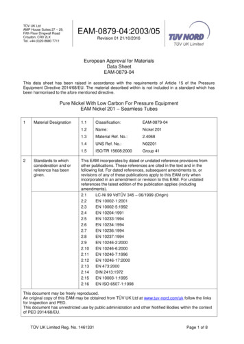
TÜV UK LtdAMP House Suites 27 – 29,Fifth Floor Dingwall RoadCroydon, CR0 2LXTel. 44-(0)20-8680 7711EAM-0879-04:2003/05Revision 01 21/10/2016European Approval for MaterialsData SheetEAM-0879-04This data sheet has been raised in accordance with the requirements of Article 15 of the PressureEquipment Directive 2014/68/EU. The material described within is not included in a standard which hasbeen harmonised to the afore mentioned directive.Pure Nickel With Low Carbon For Pressure EquipmentEAM Nickel 201 – Seamless Tubes12Material DesignationStandards to whichconsideration and orreference has kel 2011.3Material Ref. No.:2.40681.4UNS Ref. No.:N022011.5ISO/TR 15608:2000Group 41This EAM incorporates by dated or undated reference provisions fromother publications. These references are cited in the text and in thefollowing list. For dated references, subsequent amendments to, orrevisions of any of these publications apply to this EAM only whenincorporated in an amendment or revision to this EAM. For undatedreferences the latest edition of the publication applies (includingamendments).2.1LC-Ni 99 VdTÜV 345 – 06/1999 (Origin)2.2EN 10002-1:20012.3EN 10002-5:19922.4EN 10204:19912.5EN 10233:19942.6EN 10234:19942.7EN 10236:19942.8EN 10237:19942.9EN 10246-2:20002.10EN 10246-6:20002.11EN 10246-7:19962.12EN 10246-17:20002.13EN 473:20002.14DIN 2413:19722.15EN 10003-1:19952.16EN ISO 6507-1:1998This document may be freely reproduced.An original copy of this EAM may be obtained from TÜV UK Ltd at www.tuv-nord.com/uk follow the linksfor Inspection and PED.This document has unrestricted use by public administration and other Notified Bodies within the contextof PED 2014/68/EU.TÜV UK Limited Reg. No. 1461331Page 1 of 8
TÜV UK LtdAMP House Suites 27 – 29,Fifth Floor Dingwall RoadCroydon, CR0 2LXTel. 44-(0)20-8680 7711345EAM-0879-04:2003/05Revision 01 21/10/2016Limiting DimensionsMelting MethodProduction Method /Delivery ConditionDimensionsThickness (mm)Diameter (mm)Up to and including 25mmUp to and including 200mm4.1Electric Arc Process4.2Induction Furnace Process5.1Hot Rolled5.2Cold Rolled5.3ExtrudedSoft Annealed (see section 10)The products shall be free from surface and internal defects which mightimpair their usability67Application Temp.6.1-10o to 600oC6.2The material is also suitable for use below -10oC. For suchcases, impact values and verification procedures shall beagreed at the time of ordering.Chemical Composition% Composition by 8.1Mechanical andTechnologicalRequirementsRp0.2 N/mm2Rp1.0 N/mm2Rm N/mm2Min 80Min 105340/540Verification Test Direction8.2Tensile Properties8.3Rp0.2Rp1.0Rm2)Tensile Properties at Room TemperatureA%Min 40(both 5d and 5.65 So)Longitudinal (see section 9)Minimum proof and tensile strength values at ElevatedTemperature oC1)1002003004005002Requirement 0)(65)1501) For design calculations no interpolation between stated values is permitted (unless the design code explicitlyprovides for it). The values at the higher temperature shall be used.2) Rm values for reference only.The values in brackets are above the intersection with the calculated creep properties for 100,000 hours (seesection 15).The property values are taken from VdTÜV 345-06.99TÜV UK Limited Reg. No. 1461331Page 2 of 8
TÜV UK LtdAMP House Suites 27 – 29,Fifth Floor Dingwall RoadCroydon, CR0 2LXTel. 44-(0)20-8680 77118Other PropertiesEAM-0879-04:2003/05Revision 01 21/10/20168.48.5Minimum Impact Properties at room temperature (Charpy V) EN10045-1Longitudinal direction: KV 120 JTransverse direction : KV 80 JHardness Brinell HB – EN 10003-1Or Hardness Vickers HV – EN ISO 6507-1Both HB and HV: 130 max8.6Modulus of Elasticity KN/mm2oTemperature 0Reproduced from VdTÜV 345 06/99 (with mistake in source document regarding order ofunits corrected.8.7Technological RequirementsOutside Dia. D(mm)Wall Thickness T (mm) 2 2 16 16 251) 18Flattening testFlattening test 18 150Flattening testRing Expanding test1)Flattening test 150 200-Ring Tensile testRing Tensile test-1) The test may, at the discretion of the manufacturer, be replaced by a drift test or ringtensile test.Flattening test: specimens shall be flattened until the distance betweenthe platens “H” is achieved using:T wall thickness (mm)(1 c) TH Where D outside diameter (mm)c T/Dc constant 0.1Ring expanding test specimens shall be expanded until fracture occurs.The fracture shall be of a clean ductile nature. If a 40% expansion isreached the test may be discontinued.Drift Expanding test: The diameter of the specimen shall be increased by30% and when examined shall shown no signs of cracking without theuse of magnifying aids.Ring Tensile test: Specimens shall have a clean ductile fracture.Flattening and expanding tests shall show no signs of cracking withoutthe use of magnifying aids.TÜV UK Limited Reg. No. 1461331Page 3 of 8
TÜV UK LtdAMP House Suites 27 – 29,Fifth Floor Dingwall RoadCroydon, CR0 2LXTel. 44-(0)20-8680 77119TestingEAM-0879-04:2003/05Revision 01 21/10/20169.1Type of Inspection and TestTest / InspectionFrequencyReferenceCast AnalysisOne per castSection 7Product AnalysisOne per cast (ifrequired and agreedat the time of orderingby the purchaser).Section 7Positive Material I/DAll itemsSection 79.2Tensile Test at Room TemperatureFrequency1 Longitudinal test per castsize per heat treatment lot forevery 100 tubes or partthereof.9.3Frequency1 test per cast from theproduct with the largestthickness.Section 8.3 andEN 10002-5ReferenceSection 8.4 andEN 10045-1Hardness TestFrequencyAll Mechanical Test Samples/ CouponsTÜV UK Limited Reg. No. 1461331ReferenceImpact TestingVerification of impact properties is only requiredwhen specified by the purchaser at the time ofordering.The values stated in section 8.4 shall be theminimum average of 3 specimens, with only oneindividual specimen value allowed up to amaximum of 30% lower.9.5Section 8.1 andEN 10002-1Elevated Temperature Tensile TestsFor tubes withoperatingtemperatures 100oC9.4ReferenceReferenceSection 8.5Page 4 of 8
TÜV UK LtdAMP House Suites 27 – 29,Fifth Floor Dingwall RoadCroydon, CR0 2LXTel. 44-(0)20-8680 77119TestingEAM-0879-04:2003/05Revision 01 21/10/20169.6Leak TightnessTest MethodFrequencyHydraulic pressure testwith water at 80 bar1),duration 5 secminimum.Alternatively EddyCurrent Testing maybe employed.All TubesReferenceEN 10246-21) Pressures greater than 80 Bar may be used, where agreed. However under nocircumstances shall the test pressure be such as to result in the stress exceeding the Rp0.2or Rp1.0 proof strength.Using:P 20 x S x T/DWhere:P Test pressure in barS 86% of the minimum specified Rp0.2 proof strength in N/mm 2 (Referencethe formula from DIN 2413 with a 1.1 safety factor)T Minimum wall thickness in mmD Outside diameter in mm9.7Non-destructive TestsTestFrequencyUltrasonic Test2) 3)All tubesReferenceEN 473 or equivalentEN 10246-6, 7 or 172) The ultrasonic test shall be performed in accordance with EN 10246-7 (longitudinalimperfections), and the acceptance criteria shall be Level U2 subcategory C. This test maybe dispensed with where the tube is being used inside a pressure vessel (internal tubes).The order shall specify whether internal use is intended.3) Ultrasonic testing for transverse or laminar imperfections, if required, shall be agreed atthe time of ordering.9.8Visual Inspection 4)FrequencyReferenceAll bars9.9Dimensional Inspection 4)FrequencyReferenceAll bars4) 100% inspection of all tubes by the manufacturer. Dimensional tolerances shall be agreedbetween the manufacturer and purchaser at the time of ordering.9.10Technological TestsTestFlattening TestRing Tensile TestDrift Expanding TestFrequency1 test piece from 1 endof each tube or factorylengthReferenceSection 8.7 andEN 10233EN 10234EN 10236EN 10237Ring Expanding TestTÜV UK Limited Reg. No. 1461331Page 5 of 8
TÜV UK LtdAMP House Suites 27 – 29,Fifth Floor Dingwall RoadCroydon, CR0 2LXTel. 44-(0)20-8680 77111011EAM-0879-04:2003/05Revision 01 21/10/2016Heat TreatmentJoiningMethodTemperaturesHolding TimesSoft Annealing700 to 850oC2 to 4 min/mmof thicknessStress ReliefAnnealing550 to 650oC30 min to 3 hrs.11.1CoolingAirWeldingThis material has, historically, proven suitable for fusion welding by: theMMA (111) welding process with coated electrodes using the appropriatefiller material, e.g. material No.:2.4156. Also the processes TIG (141) andMIG (131) using the appropriate filler material, e.g. No.:2.4155Information supplied by the consumable manufacturer on the filler wiressuitability must be considered, especially with regard to sulphur sensitivityand both low and elevated temperature properties.The material does not normally require pre heat and should be welded inthe soft annealed condition.Stress relief annealing may take place after welding.Where cold forming exceeds 5%, stress relief annealing shall beperformed prior to welding.Consultation with the material manufacturer’s technical department isrecommended when choosing a filler wire or welding process.12Forming12.1Hot and ColdThe material is suitable for both hot and cold forming subject to thefollowing provisions:13Marking1)Hot forming shall occur between 800 to 1250oC followed by softannealing (see section 10).2)Where cold forming deformation exceeds 5% a stress reliefanneal or soft anneal shall be performed (see section 10).3)The material is sensitive to sulphur above 400oC, therefore thesurface should be carefully cleaned before any welding or heattreatment.4)It is important that the furnace atmospheres for processing aresulphur free.13.1All Tubes1)Manufacturer’s Identification Mark2)Cast / Melt Number3)Test or Manufacturing Batch Number4)Material Grade5)EAM Reference No.Markings shall normally be by permanent ink marking or Vibro-etching.TÜV UK Limited Reg. No. 1461331Page 6 of 8
TÜV UK LtdAMP House Suites 27 – 29,Fifth Floor Dingwall RoadCroydon, CR0 2LXTel. 44-(0)20-8680 771114Inspection DocumentsEAM-0879-04:2003/05Revision 01 21/10/201614.11)Document TypeMaterial manufacturers shall supply documentation affirmingcompliance with this EMA.This document shall normally be in the form of an inspectioncertificate in accordance with EN 10204 3.1.B.Note: Where a material manufacturer has an appropriate quality assurance system,certified by a competent body, established with the community and having undergone aspecific assessment for materials, certificates issued by the manufacturer are presumed tocertify conformity with the requirements of section 4.3 of Annex 1 of the PED.2)If an inspection document in accordance with EN 10204 3.1.C or3.2 is specified, the purchaser shall notify the manufacturer ofthe name and address of the organisation or person who is tocarry out the inspection and produce the inspection document.In the case of the inspection report 3.2 it shall be agreed whichparty shall issue the certificate.Note: The affirmation of the compliance of the delivery with this EMA is not a mandatoryrequirement of EN 10204. Such affirmation – as is required by the PED 2014/68/EU inAnnex 1 4.3 first paragraph – can be added into the text of the material certificate, when itis signed by the manufacturer. It could also be provided in a separate document. In thecase the material certificate is signed by a third party, the affirmation shall be contained ina document which is (also) signed by the manufacturer.14.2Contents of Inspection Documents1)Details of the manufacturer2)Details of the purchaser (if required)3)Description and dimensions of the product4)Supply conditions5)Ladle analysis6)Product analysis (if required)7)Results from mechanical property tests8)Heat treatment applied9)Results from other applicable tests (e.g. NDT, Leak Test, PMI,Technological Tests)10)Marking and identification11)Affirmation of compliance with this EAM12)Declaration of the status of the Manufacturer’s Quality System(including the name of the competent body having certified thequality system, if applicable).TÜV UK Limited Reg. No. 1461331Page 7 of 8
TÜV UK LtdAMP House Suites 27 – 29,Fifth Floor Dingwall RoadCroydon, CR0 2LXTel. 44-(0)20-8680 771115Calculated CreepPropertiesEAM-0879-04:2003/05Revision 01 21/10/2016TemperatureoCalculated 1% creep strain strengthcharacteristics (multiplied by factor 1.5)1) 5652484440363229262320171513119876.561) The figures above are calculated creep strain strength characteristics valueswhich correspond to the lower scatter band of the 1% creep strain limit multipliedby 1.5.N.B. Between the 1% creep strain limit and the creep rupture strength there is adifference which is greater that 1.5 x 1% creep strain limit. In order to avoidunacceptable deformations the creep rupture strength cannot be used forcalculation.For design calculations no interpolation between stated values is permitted(unless the design code explicitly provides for it). The values at the highertemperature shall be used.The characteristics in the table above are reproduced from VdTÜV 345 06/99TÜV UK Limited Reg. No. 1461331Page 8 of 8
EAM-0879-04:2003/05 Revision 01 21/10/2016 TÜV UK Limited Reg. No. 1461331 Page 1 of 8 European Approval for Materials Data Sheet EAM-0879-04 This data sheet has been raised in accordance with the requirements of Article 15 of the Pressure Equipment Directive 2014/68/EU. The material described within is not included in a standard which has

