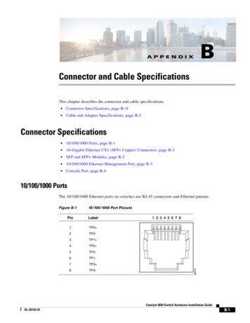
Transcription
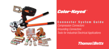
Connector System GuideCompression ConnectorsGrounding ConnectorsTools for Industrial Electrical Applications
Step OnePreparing the Cable
33Strip the insulation carefully to avoid nickingor cutting conductors (wire brush if required).Nicked StrandsStrands CutGood StripStrip the insulation to the proper lengthso that conductors can be fully insertedinto the connector barrel.Strip Length Too LongStrip Length Too ShortStrip Length Just Rightxx
S t e p Tw oDetermining the Proper Connector
55Determine the proper Color-Keyed Connector for the cable sizebeing used. Connectors marked with just cable size or “CU” should be used oncopper conductors only. Connectors marked “AL9” with the cable size should be used onaluminum conductors only. Connectors marked “AL9CU” with the cable size may be used onthe aluminum or copper conductors.Note: Aluminum lugs with a “9” indicate 90ºC rating.Connectors are marked to show cable size.Cable Size
Step ThreeC h o o s i n g To o l a n d P r o p e r D i e
77Select the properinstalling die andappropriate tool.Die Code EngravingColor CodesColor-Keyed Connectors havecolored bands or colored dots thatcorrespond to color markings ofthe dies.Connectors and dies also have a diecode number marked or stampedon them. Dies have a code numberengraved in the crimp surface.Die Code MarkingColored StripColored Bands
Step FourInstallation and InspectionLocate tool with correct die inproper position on connectorand activate tool.Color-Keyed Connectors are banded bycolored stripes or engraving to indicatelocation of die on connector for compression.CopperDie locatedBETWEEN bandsAluminumDie locatedON bands
99When making multiplecrimps, make the first crimpnearest the tongue and worktowards the barrel end.Die location for compressionTongueBarrel1st crimp2nd crimpWhen properly crimped, the die code number willbe embossed on the connector for easy inspectionto determine if correct die and connector combinationwere used.Thomas & Betts uses “fullwidth” and “half-width”dies dependent onconnector size and toolused. “Half-width” diesare marked with the letter“H” after the die codenumber.Colored bandsDie code embossedRefer to the instruction sheet supplied with the connectors forinformation regarding strip length, die selection and number of compressions.
To o l a n d D i e S e l e c t i o n C h a r t f o r P o w e r C o n n e c t o r sCopper8 AWG6 AWG4 AWG2 AWG1 AWG1/02/03/04/0250 kcmil300 kcmil350 kcmil400 kcmil500 kcmil600 kcmilConnector 325/24450/24550/24775/24 (short)775/24 (long)925/24*1100/24AL/CU10 AWG8 AWG6 AWG4 AWG2 AWG1 AWG1/02/03/04/0250 kmcil300 kcmil350 kcmil400 kcmil1325/24**700 kcmil750 kcmil800 kcmil900 kcmil1000 kcmil500 kcmil650 kcmil1925/24700 kcmil750 kcmil800 kcmil1000 kcmilColor-KeyedDie EENPINKPINKBLACKORANGEPURPLEYELLOWN/AN/A*Standard barrel only. Long barrel requires Brown 87H1010TBM45SC-TAPS ONLYTBM4STBM840TBM8-750/-1TBM-8/8STBM8 Die Cat. No.TBM-5/5STBM5 Die Cat. 4584/0 only13468**Standard barrel only. Long barrel requires Black 106HTBM6/6S (25000)Cat. No. Upper DieCat. No. Lower 476134721347613472134761347913476134781347813642M (13400) Hydraulic HeadDie Cat. No.Die Code 01174266H1174371H1174476H1174580HTBM12 Hydraulic HeadDie Cat. No.Die Code D-1112H115H
To o l a n d D i e S e l e c t i o n C h a r t f o r P o w e r C o n n e c t o r sConnector SizeCopper8 AWG6 AWG4 AWG2 AWG1 AWG1/02/03/04/0250 kcmil300 kcmil350 kcmil400 kcmil500 kcmil600 4325/24450/24550/24775/24 (short)775/24 (long)925/24*1100/24AL/CU10 AWG8 AWG6 AWG4 AWG2 AWG1 AWG1/02/03/04/0250 kmcil300 kcmil350 kcmil400 kcmil1325/24**700 kcmil750 kcmil800 kcmil900 kcmil1000 kcmil500 kcmil650 kcmil1925/24700 kcmil750 kcmil800 kcmil1000 kcmil*Standard barrel only. Long barrel requires Brown 87HColor-KeyedDie HTBM14BSCR/14M/13100A,BPLT14BSCR, TBM14MC, JB12B, TBM14RHTBM62BSCRDie Cat. TON766TON80Die Code No.212429333742455054624550546066H71H76H80HDie Cat. 0TBM6266TBM6271TBM6276TBM6280Die Code No.212429333742455054624550546066717680Die Cat. 51215517Die Code No.212429333742455054624550546066H71H76H80H6TON 15-CK99H106H1504115H99H106H107H112H115H**Standard barrel only. Long barrel requires Black 106HTBM15BSCR/15I***,BPLT15BSCRDie Cat. 5121551715606155061551115536-CKDie Code 9H106H107H112H115H125H140H150H*** 15500 Series dies require 15500-TB adapter. 15500F for full size die to fit TBM15I without adapter21940 (40 TON)Die Cat. No.Die Code 08114161141811419991061071121151251401501111
To o l a n d D i e S e l e c t i o n C h a r t f o r C o p p e r H - Ta p sConductor Size Code Cable (Flex Cable)InstallationMainBranch 1Branch 2Branch 3H-TapColorDieTool# of CrimpDie EmbossingStrip Length (in.)Insulating Cover8-14 (8-14)8-14 (8-14)––CHT814-10GREEN15CA37RCH*Group 1137R1/2HTC2S2-6 Str. / Sol. (2-8)2-6 Str. / Sol. (2-8)8-14 (8-14)8-14 (8-14)CHT214-9BROWN15CA71RCH*Group 1171R7/8HTC40250-2 (4/0-2)8-14 (8-14)8-14 (8-14)–CHT250214-8PURPLE15CA80RCH*Group 2180R1-1/8HTC40250-2 (4/0-2)2-6 Str. / Sol. (2-8)CHT25014-7PURPLE15CA80RCH*Group 2180R1-1/8250-2 (4/0-2)250-2 (4/0-2)––CHT2502-6PURPLE15CA80RCH*Group 2180R13/16HTC40500-4/0 (350-4/0)250-1/0 (4/0-1/0)1 Str. 2-6 (1-8)8-14 (8-14)8-14 (8-14)–CHT50010-5BROWN15612CHGroup 22N1-1/2HTC500HTC40500-4/0 (350-4/0)500-4/0 (350-4/0)––CHT50040-4BROWN15612CHGroup 22N1-1/2HTC500750-350 (550-500)4/0-1/0 (250-1/0)1 Str. 2-6 (1-8)2-14 (2-14)CHT75010-3YELLOW15620CHGroup 21Z1-1/2HTC500750-350 (550-500)750-350 (550-350)––CHT750350-2YELLOW15620CHGroup 21Z1-3/8HTC500750 (750-500)350-4/0 Str. & Flex––CHT75040-11YELLOW15620CHGroup 21Z1-1/8HTC500(750-500) (750)(750-500) (350)––CHT750350-1FWHITE15620CHFGroup 21F1-1/8HTC1000*Requires optional adapter 15500-TB when used with hydraulic head TBM15I and TBM15BSCR1212Group 1 TBM15I, TBM15BSCR, TBM14, TBM14BSCR, 13100A, JB12B, TBM14RH, TBM14MCGroup 2 TBM15I, TBM15BSCR
To o l a n d D i e C h a r t f o r S t a n d a r d C - Ta p sC-Tap12145470514161010812610, 1288, 10, 124 or 58, 10, 1266, 836,8, 10, 12***4 or 56, 52341231/0122/01/013/02/01/06, 8, 10, 12534, 5, 6, 8, 10, 124, 53, 44, 5, 6, 8, 10, 123, 42, 33, 4, 5, 6, 8, 10, 122, 31, 32, 3, 4, 5, 6, 8, 10, 121, 21/0, 30Group 1TBM62BSCRGroup 2Group 3DieDie# of CrimpDie 740Insulation ChoiceAdhesive PadShrink TubingHS12-6Accommodates this Entire RangeBranch 1Accommodates this RangeCode Wire Comb. Cir. Area *When using 3 AWG on main and 12 AWG on branch with smart tools and dies, 12 AWG wire must be doubled (hair-pinned) and placed on branch for crimpingGroup 1 TBM6H / TBM62BSCRGroup 2 TBM45S / TBM41E and require 2 compressions within each crimp areaGroup 3 TBM5 / 5S, TBM6 / 6S, TBM8/8S, TBM6H and require 1 compression within each crimp area1313
To o l a n d D i e C h a r t f o r L a r g e C - Ta p Main Copper RangeBranch -64/0-1/0750-4/0C-Tap*Color54755BLUEToolsRegular ToolsDiesDie M-1Smart ToolDieTBM8-750CL# of Crimps***1Insulation ChoiceAdhesive PadShrink Tubing1211746-TBTBM12D-354760# of 03454790* For tin plate finish add "TP" to Cat. No. listed (Example: 54755TP) **Use with adapter Cat. No. 15500-TB (Note: If 15500 dies have a suffix "F", they are full sized dies and can be used with the TBM15I without an adapter.) ***When using compact copper cable, apply addidional overlappingcrimps so that C-Tap is crimped from end to end. 11000 series dies go with 13642M tool, TBM12D-# series dies go with TBM12 tool, and 15500 series dies go with TBM14M/14BSCR/13100A/TBM15I/15BSCR. ****#6 AWG branch branch must be doubled.1414
Conductor PropertiesConductorsAreaStrandingSize(AWG or kcmil)181816161414121210108864321mm2Circular 0.0170.0270.0420.0530.0670.087Direct-Current Resistance at 75oC .261.280.8080.5080.4030.3190.2531515
Conductor Properties (Continued)ConductorsAreaStrandingSize(AWG or 00mm2Circular 292.472.642.952.522.722.822.913.093.25FPN: The construction information is per NEMA WC8-1992 or ANSI/UL 1581-1998.The resistance is calculated per National Bureau of StandardsHandbook 100, dated 1966, and Handbook 109, dated 1.0941.15270–625 TABLESNATIONAL ELECTRICAL CODE, 2002 urrent Resistance at 75oC 050.05290.04240.03530.03030.02820.02650.02350.0212
XHHW-2,ZW-260oC(140oF)Aluminum or Copper-Clad 21477617382460521Correction FactorsType .000.960.910.870.820.760.710.580.41For ambient temperatures other than 30oC (86oF), multiply the ampacitiesshown above by the appropriate factor shown 743153433763872974154
Color Codes Colored Bands Colored Strip Die Code Engraving Die Code Marking Select the proper installing die and appropriate tool. Color-Keyed Connectors have colored bands or colored dots that correspond to color markings of the dies. Connectors and dies also have a die code number marked or stamped on them.Dies have a code number engraved in the crimp surface. 7 7. Step Four Installation .