Transcription
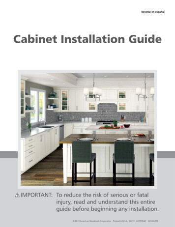
Reverso en españolCabinet Installation GuideIMPORTANT: To reduce the risk of serious or fatalinjury, read and understand this entireguide before beginning any installation. 2019 American Woodmark Corporation Printed in U.S.A. 02/19 XO999040 GEN96272
Thank you andcongratulations on theinvestment in qualitycabinetry for your home!The cabinets you have purchased represent today’s best valuein cabinetry for kitchen, bath and every room in between. Thesecabinets are manufactured to the highest quality standards andbacked by American Woodmark Corporation.Warranty Information: A full copy of our warranty may beobtained from your retailer, builder or distributor or by visitingwww.americanwoodmark.com/warranty.General Safety WarningsWARNINGTO REDUCE THE RISK OF DEATH OR SERIOUS INJURY, READAND HEED ALL WARNINGS AND INSTRUCTIONS.USE SAFETY PRECAUTIONS AT ALL TIMES. MAINTAIN ACLEAN, WELL-ORGANIZED WORKSPACE. WEAR SAFETYGOGGLES THAT COMPLY WITH ANSI Z87.1 AND ALLPROTECTIVE EQUIPMENT RECOMMENDED BY THEMANUFACTURERS OF THE TOOLS YOU WILL BE USING.ONLY ATTACH CABINETS TO CENTER OF WALL STUDSACCORDING TO INSTRUCTIONS.THIS INSTALLATION GUIDE APPLIES TO ONLY WOODSTUD CONSTRUCTION. IF YOU ARE SECURING CABINETSTO ANOTHER MATERIAL, CONSULT AN INSTALLATIONPROFESSIONAL TO IDENTIFY THE PROPER FASTENERS.NEVER USE NAILS OR DRYWALL SCREWS TO INSTALLCABINETS BECAUSE DOING SO MAY DAMAGE CABINETS ORFAIL TO PROPERLY SECURE THEM WHICH MAY RESULT INDEATH OR SERIOUS INJURY.2ContentsGeneral Safety Warnings 2Preparation.3Preparing Walls and Floors 3Suggested Tool and Material List 4Prepare Wall & Corner Wall Cabinets 5Hang the Wall Cabinets One at a Time 6Install Fillers (where applicable) 8Install End Panels (where applicable) 9Install Base Cabinets.10Install Moldings (if applicable) 11Final Assembly and Cleanup 13Door Hinge Adjustment.14Drawer Head Adjustment.14Drawer Installation.15Drawer Glide Adjustments 15Drawer Removal.15Care and Cleaning.16INSTALLATION INSTRUCTIONS – LIABILITY DISCLAIMERWhen you use these instructions, you are consenting to be boundby the provisions in this paragraph. These instructions provide anillustrative method for installing American Woodmark Corporation(“AWC”) cabinets. AWC’s instructions are not intended to addressevery possible contingency that might be encountered duringinstallation or to endorse the use of any particular tools.DISCLAIMER: AWC HAS DILIGENTLY TRIED TO ILLUSTRATEAND DESCRIBE THE INSTALLATION OF THE PRODUCTS IN THISLITERATURE CLEARLY AND ACCURATELY; HOWEVER, SUCHILLUSTRATIONS AND DESCRIPTIONS DO NOT EXPRESS OR IMPLY AWARRANTY OF ANY KIND, INCLUDING BUT NOT LIMITED TO ANYWARRANTY THAT THE PURCHASER WILL BE ABLE TO OBTAIN APARTICULAR RESULT, OR THAT THE PRODUCTS OR INSTRUCTIONSARE MERCHANTABLE, OR FIT FOR A PARTICULAR PURPOSE, ORTHAT THE INSTALLED PRODUCTS WILL NECESSARILY CONFORMTO THE ILLUSTRATIONS OR DESCRIPTIONS OR DIMENSIONS.THESE INSTRUCTIONS DO NOT ENLARGE OR OTHERWISE MODIFYTHE LIMITED WARRANTY RECEIVED WHEN YOU PURCHASEDYOUR CABINETS, IF ANY. AWC HEREBY EXPRESSLY DISCLAIMSALL WARRANTIES AND ALL LIABILITY FOR ANY CLAIMS FORINJURY OR DEATH RELATED TO OR BASED UPON THE USE OFTHESE INSTALLATION INSTRUCTIONS AND ANY INSTALLATIONINSTRUCTIONS OTHERWISE PROVIDED BY AWC. AWC IS NOTRESPONSIBLE FOR ANY INACCURACIES, OMISSIONS OR TYPOS INTHIS GUIDE.
PreparationBefore You Begin1Check your inventory to be sure you received your entireorder. If there are any missing or improper parts, contactyour designer or customer service.2AWC recommends that no fewer than two people worktogether to install these cabinets.3Read and understand the entire installation guide prior tobeginning the install.Safety PrecautionsDANGERTO REDUCE THE RISK OF SERIOUS OR FATAL INJURY FROMFIRE, EXPLOSION OR ELECTROCUTION, IF GAS LINE ORELECTRICAL WORK IS INVOLVED, HAVE THE WORK DONE BYA UTILITY COMPANY OR QUALIFIED SERVICE PROFESSIONAL.TO REDUCE THE RISK OF SHOCK, EXPLOSION OR INJURY,TURN OFF ALL GAS, ELECTRICAL AND WATER CONNECTIONSPRIOR TO PERFORMING ANY WORK. SHUT OFF THE POWERTO ALL APPLIANCES AND RECEPTACLES IN THE KITCHEN,INCLUDING LIGHTS, AT THE FUSE-BREAKER BOX. USE ACIRCUIT TESTER TO MAKE SURE POWER IS OFF.Once you have ensured that the gas, water and electric in theroom are turned off, that the plumbing, gas and power suppliesare properly capped, and have removed the old cabinetry andbaseboards, you need to assess the room.Take special note of the floors and walls. Use a level or straightedgeto determine high spots and other imperfections. Mark any bumpyor bulging areas. You may have to prep the walls and floors ifthings are not plumb, level and square. (Many people prefer torepaint and replace the flooring while the room is empty.) Thetime you spend preparing the room will ensure smoother, easierinstallation of the cabinetry.Prepare the Walls and FloorsWe know that homes settle and things may not always be perfectlyflat and level. But there are ways to address this issue wheninstalling cabinetry. Here are a few steps that will help you get offto a good start.1Locate and mark all the studs using a stud finder. (To verifythe position of your studs, drive a small finishing nail intothe wall in an area that will be covered up by a cabinet.)2Recheck your measurements. Make sure the cabinetdrawings match the space.3Gather the tools you will need.Suggested Tool and Material List ANSI Z87.1 Rated Safety Goggles Layout from Designer Framing Square Hammer Pry Bar Phillips and Flathead Screwdrivers Level Tape Measure Pencil Straight Edge Drill Properly Rated Extension Cord 7 32” Drill Bit for Pre-drilling the Hanging Rail 3 32” Drill Bits for Frame & Filler Attachment Pilot Holes Jigsaw or Table Saw Miter Box Clamps or C-Clamps Stud Finder 6’ Step Ladder Wood Shims Pin Nailer Small Finish Nails 1 x 2 or 1 x 3 Furring Strips Scrap Lumber (for 55” Propping Stick or T-Brace) Circuit Tester #10 x 21 2” Pan Head Screws (for wall attachment to stud) #8 x 21 2” Trim Head Screws (for frame attachment)WARNINGFAILURE TO PROPERLY SECURE THE CABINETS MAY RESULTIN SERIOUS INJURY! THE SCREWS RECOMMENDED AREFOR INSTALLATIONS INVOLVING DRYWALL AND WOODSTUD CONSTRUCTION, NOT FOR CONCRETE OR BRICK. IFSECURING CABINETS TO ANOTHER MATERIAL, CONSULT ANINSTALLATION PROFESSIONAL TO IDENTIFY THE PROPERFASTENERS.3
Step 1MeasurementIn order for cabinets to function properly, they must be installedlevel, plumb and flush with each other. This is easy enough toachieve with some advanced planning.line the same1.4 Now measure up from the wall cabinet base111distance as the height of your cabinets (30 8”, 36 8”, 39 8”or 421 8”). This will be the top line for the wall cabinets. Allnon-standard height wall cabinets need to line up with thistop line as well. (Figure 3)First, locate the floor’s highest point. In order to do this,place your level at the base of the wall, checking severalplaces along the wall until you find the high point in thefloor. Mark this spot. (Figure 1)1.1Wall cabinet top lineSoffit or ceiling30 1/8”, 36 1/8”,or 42 1/8”LevelWall stud locationsStraight edge19 3/8”53 7/8”20 1/2”Toekick lineMark floor athigh point84”, 90”,or 96”Wall cabinetbase lineWall stud locations34 1/2”Toekick lineHighest pointlevel line20 1/2”Figure 3Shim to levelHighest point level lineFigure 111.2 Measure up from the high point 34 2” and draw a level lineacross the wall to establish the top of the base cabinets. Ifinstalling cabinets before your flooring, be sure to allow forthe thickness of the material you plan to use. (Figure 2)NOTE: IF YOU HAVE A LOW CEILING OR SOFFIT, YOU MUSTMAKE SURE THAT THE WALL CABINETS WILL FIT PROPERLYBETWEEN YOUR LEVEL LINE AND THE TOP.1.5 Using the 1 x 2 or 1 x 3 furring strips, screw a support railinto the studs with 2” wood screws below the baseline youhave drawn for the wall cabinets. This will help supportthe weight of the wall cabinets, and give you something torest the cabinets on when installing them. Make sure yoursupport rail (sometimes called a cleat or ledger board) islevel. (Figure 4)31.3 Then measure up from there another 19 8”. This will be thebaseline for the wall cabinets. (When you are finished, thewall cabinets will sit at 537 8” above the high spot in thefloor). (Figure 2) Please refer to your design elevations toverify dimensions specific to your layout.Wall cabinet top lineSoffit or ceilingWall stud locationsWall cabinet base lineLevelStraight edgeWall cabinetbase line19 3/8”34 /2” fromhighest pointlevel line120 1/2”Temporarysupport rails53 7/8”Temporary support railToekick lineFigure 4Figure 24Wall studlocations2” Wood screwsscrew into wall studShim to levelHighest point level line1.6You are now ready to join the wall cabinets.
Step 2Prepare Wall & Corner Wall CabinetsIt is recommended that you install wall-mounted cabinetsfirst so the base cabinets won’t be in your way as you work. Tobegin, most people find it helpful to lay out the cabinets on thefloor in position, level and plumb, and join them before hanging.2.1NOTE: A BLIND WALL CABINET FILLS THE VOID OF THECORNER WITH USABLE STORAGE. THE DOOR COMES PREMOUNTED ON THE LEFT SIDE, BUT CAN BE MOVED TO THERIGHT DEPENDING ON YOUR DESIGN (SEE DIAGRAM A).Remove all shelves and doors. You might want to mark (orcarefully stack them in position) for reinstalling later. Thiswill make the cabinets lighter and easier to handle.(Figure 5)Blind wall cabinetDoor hingeRemove screwFiller –refer to your layoutfor the appropriate fillerwidth and distance topull the cabinet fromthe wall.Cabinet face frameAdjacentwall cabinetDIAGRAM A2.4 Using a level, make sure each cabinet is level and eachRemove doors and shelvesFigure 5face frame (front of the cabinet) is flush with the adjacentcabinet. A pry bar and shims can be used temporarily to geteverything level and plumb. (Figure 7)2.2 Refer to the layout provided by your designer and start withthe corner cabinet (if there is one) and place it on the floorbelow where it is to be mounted.NOTE: WHEN INSTALLING A BLIND WALL CABINET, MAKESURE THE CABINET IS PULLED OUT FROM THE CORNER THEAPPROPRIATE DISTANCE CALLED FOR IN YOUR KITCHENPLAN. ALWAYS BE SURE TO USE A FILLER TO ALLOW FORHINGE CLEARANCE.Shim as requiredTemporarysupport railsLevel2.3 One by one, align the remainder of the cabinets and fillersin position on the floor using the plan provided by thedesigner. (Figure 6)Corner wall cabinetTemporarysupport railsAdjacent wall cabinetFigure 7Shim as requiredWall stud locationsNOTE: IT IS PARTICULARLY IMPORTANT TO INSTALL THE FIRSTCABINET LEVEL AND PLUMB, BOTH FROM SIDE-TO-SIDE ANDFROM FRONT-TO-BACK BECAUSE EACH ADDITIONAL CABINETWILL BE ALIGNED WITH THE FIRST ONE.NOTE: PLACE TALL CABINETS FOR SPACING, BUT DO NOTASSEMBLE.Wall studlocationsFigure 6Shim as requiredArrange cabinetsaccording to planContinuedContinued5
WARNINGTO PROPERLY SECURE WALL CABINETS LARGER THAN15” WIDE, AND TO REDUCE THE RISK OF CABINETSFALLING AND CAUSING SERIOUS INJURY, USE AT LEAST 4INSTALLATION SCREWS AND MAKE SURE THE SCREWS GOINTO THE STUDS AT LEAST 1”.will need to clamp2.5 In order to attach two cabinets, you3them together first. Then, drill a 32” pilot hole in threeplaces along the hinge side of the frame ensuring that theholes do not interfere with the hinge placement. Finally,drive in the #8 x 21 2” frame attachment (trim head) screwsto join the two cabinets. (Figure 8) 32" pilot hole32.8 Once all cabinets are pre-assembled on the floor, measure fromthe corner to the first stud mark and transfer the measurementto the inside of the cabinet to be installed. Repeat this step foreach and every stud. Now drill 7 32” holes for mounting throughthe top and bottom hanging rails inside of the cabinet 3 4” downfrom the top and 3 4” up from the bottom. (Figure 9)There are two hanging rails across theback of wall cabinets, one at the top andone at the bottom. Drill through boththe top and bottom hanging rails at thestud location.Transfer studlocations towall cabinets 4" downfrom top3Temporarysupport rails 4" up frombottom3FrameattachmentscrewsAssembled wall cabinetsClamp face framestogether firstFigure 82.6 IMPORTANT: Check to make sure the frames are even andplumb.Figure 9Wall stud locations2.9 Fillers must also be pre-drilled and screwed into position.Refer to STEP 4–INSTALL FILLERS for more informationabout measuring, cutting and installing fillers.2.7 Continue for the remainder of the cabinets and fillersfollowing the layout provided by your designer.Step 33.1Hanging Wall CabinetsRecheck the pre-assembled cabinets for level and plumb,then disassemble wall cabinets before installing.WARNINGTO REDUCE THE RISK OF SERIOUS OR FATAL INJURY,REMOVE ALL SCREWS AND DISASSEMBLE WALL CABINETSBEFORE INSTALLING.CABINETS MAY BE TOO HEAVY FOR ONE PERSON TO SAFELYLIFT ALONE.THIS INSTALLATION GUIDE APPLIES TO ONLY WOODSTUD CONSTRUCTION. IF YOU ARE SECURING CABINETSTO ANOTHER MATERIAL, CONSULT AN INSTALLATION6PROFESSIONAL TO IDENTIFY THE PROPER FASTENERS.NEVER USE NAILS TO INSTALL CABINETS BECAUSE DOINGSO MAY DAMAGE CABINETS OR FAIL TO PROPERLY SECURETHEM WHICH MAY RESULT IN DEATH OR SERIOUS INJURY.TIGHTENING BACK RAILS AGAINST A CROOKED WALLWITHOUT SHIMS CAN BREAK JOINTS BETWEEN THE RAILAND THE BODY OF THE CABINET, CAUSING IT TO FALL FROMTHE WALL AND POSSIBLY RESULTING IN SERIOUS PERSONALINJURY.
3.2 Start with the corner cabinet. With someone else’s help, liftit into position on the support rail and use a 2 x 4 or T-Braceat the front to prop the cabinet into place. Keep in mind,blind corner cabinets may need to be pulled out from thecorner as shown in your kitchen plan. (Figure 10)13.6 Once again, fasten the cabinet to the wall with #10 x 2 2”wall attachment (pan head) screws. Do not fully tighten.cabinet, the opening should be sealed3.7 If there is a blind corner1at this point with the 8” panel packed inside the cabinet.Pre-drill for small finishing nails or use a pin nailer. (Figure 12)Blind wall cabinetT-Brace supportsfront of cabinetSoffit or ceilingProvided 1 8" panelWall stud locationsTemporarysupport railsStart withcorner cabinet firstFigure 12Back of cabinetsupported by support railsTemporarysupport railsT-BraceWall stud locationsFigure 1013.3 Fasten the cabinet to the wall with #10 x 2 2” wall attachment(pan head) screws. Do not fully tighten the screws until allcabinets have been shimmed and properly positioned.3.4 Next, using your level against the front of the cabinet, shimwherever necessary to make sure the cabinets are perfectlyplumb (even though the walls may not be). Keep in mind,you may have to loosen the wall attachment screws slightlyto shim properly.3.5Lift the adjacent cabinet into position on the support railand brace. Using the pilot holes you created on the floor,attach the two cabinets at the face frames, making surethey are still flush when screwed together. (Figure 11)Mount adjacent cabinets,shim as requiredCorner wall cabinetTemporarysupport railsWall stud locationsFigure 11T-BraceT-Brace3.8 Continue along the walls until all cabinets are in place. If atall or utility cabinet is part of your plan, it should be addedat this point. Once again, shim for proper height and toalign so that it is perfectly plumb with the adjacent wallcabinet. Once face frames are flush, clamp, drill and screwtogether as previously described.NOTE: AT THIS POINT, YOU MAY WANT TO SET THE TALLCABINET INTO POSITION TO BE SURE IT FITS PROPERLY.NOTE: REFER TO SPECIFIC INSTRUCTIONS THAT COME WITHSPECIALTY TALL CABINETS.3.9 Once all cabinets are properly shimmed and properlypositioned, finish tightening the screws to secure thecabinets to the walls.3.10 Remove the support rails and spackle screw holes if needed.WARNINGTO AVOID RISK OF DRIVING SCREWS BEYOND THE CABINETFACE, CARE MUST BE TAKEN TO PREVENT OVER TIGHTENINGOF THE SCREWS AND DESTROYING THE INTEGRITY OF THEHANGING STRIP.TO REDUCE THE RISK OF SERIOUS INJURY OR DAMAGE FROMA LOOSE OR FALLING CABINET, WALL CABINETS GREATER THAN12” IN DEPTH OR LARGER THAN 24” IN WIDTH MUST NOT BEINSTALLED AND/OR USED AS SINGLE, STAND-ALONE CABINETSWITHOUT TAKING EXTRA PRECAUTIONS TO FULLY AND SAFELYSECURE THE CABINET TO THE WALL. ADDITIONAL MOUNTINGSUPPORT INTO A CEILING, BULKHEAD, OR SIDE WALL(S) ISALSO RECOMMENDED WHEN POSSIBLE. WHEN THIS IS NOTPOSSIBLE, THEN ADDITIONAL SUPPORT MUST BE PROVIDEDEITHER ABOVE OR BELOW THE CABINET TO SUPPORT WEIGHTAT A POINT AT LEAST 12” FROM THE WALL. THIS CAN BE DONETHROUGH ANGLE BRACKETS/BRACING, SHELVING, AND/ORADDITIONAL CABINETS AS A STAND.7
Step 4Install Fillers (where applicable)Fillers may be necessary when installing cabinets. They help allowfor odd dimensions between a run of cabinets and the wall. Theyalso allow clearance for doors and drawers to operate properlywhen turning a corner with a blind corner cabinet. Fillers andvalances often have to be trimmed to fit.4.114.3 Fasten the filler to the cabinet with #8 x 2 2” frameattachment (trim head) screws. (Figure 13)Install backer for fillersgreater than 3” to securethe filler to the wall.Measure the area requiring a filler piece. Carefully trim thefiller piece to the appropriate width with a saw.4.2 Clamp the filler in place and once again, drill a pilot hole on thehinge side of the face frame and into the filler./32” pilot hole3Hinge mountingscrew holeFillerFrameattachmentscrewClampfiller panel toface frameFigure 134.4 If using a blind corner base, secure the other end of thefiller through the inside of the cabinet with the same pilothole and frame attachment screw technique.8
Step 5Install End Panels (where applicable)WARNING5.2 When installing a refrigerator or dishwasher return, it isTO REDUCE THE RISK OF DEATH OR SERIOUS PERSONALINJURY OR PROPERTY DAMAGE, AVOID ANY CONTACT WITHPLUMBING, WIRING OR GAS LINES. THESE LINES ARE OFTENIN THE WALLS AND UNDER THE FLOOR.End panels are used to finish off a run of cabinets or box out anappliance. Make sure to install plumb and level.5.1If your application uses a finished end panel, first trim thepanel to fit and then attach the panel to the side of thecabinet. This can be done with contact adhesive or 1 2”finishing nails. (Figure 14)important to mount a cleat at the floor to secure this panel.Simply cut a piece of 1 x 2 dimensional lumber about 20”long so it is not exposed at the front of the panel. Thensecure to the floor with 2–3 fasteners (concrete screws forconcrete floors / wood screws for wood floors). Secure thecleat to the panel (DWR, RR, SFR, etc.) with 2–3 woodscrews. (Figure 15)Refrigeratoror dishwasherreturnCleatFigure 15Last cabinetFigure 14End panel9
Step 6Install Base CabinetsInstalling base cabinets is very similar to the wall cabinets above.The idea again is to lay out all the cabinets in position and makesure all cabinets are level, square and plumb.6.1Remove all shelves, drawers and doors. You might want tomark (or stack them in position) for reinstalling later. Thiswill make the cabinets lighter and easier to handle.(See Appendix for drawer removal technique.) (Figure 16)16.3 Make sure your cabinet reaches the 34 2” high level lineyou drew on the wall. If not, you may have to shim intoposition or use scrap to raise it to the proper level. If thecabinet is tilting backward, shims at the back edge willhelp. If it’s tilting forward, use the pry bar under the frontto adjust and then shim.6.4 Measure from the corner to the first stud mark and transferthe measurement to the inside of the cabinet to beinstalled. Repeat this step for each and every stud. Nowdrill 7 32” mounting holes through the center of the hangingrail inside of the cabinet.Remove doors, drawers,shelves, and sliding shelvesor roll out trays16.5 Fasten the cabinet to the wall with #10 x 2 2” wallattachment (pan head) screws.6.6 If1 there is a blind corner cabinet, seal the opening with the 8” panel packed inside the cabinet, as previously describedin the wall cabinet installation section.Figure 166.7 Next, shim the adjacent cabinet into position and check for6.2 Start with the corner cabinet (if there is one) and place itin position where it is to be mounted. When using a blindbase cabinet, make sure the cabinet is pulled out from thecorner the appropriate distance as called for in your kitchenplan. (Figure 17)Shim as requiredWall studlocationsCheck for levellevel and plumb. Once again, clamp the face frames whenthey are perfectly flush, drill pilot holes and join the twocabinets with screws as previously described.NOTE: YOU MAY NEED TO CREATE CUTOUTS FOR PLUMBINGAND ELECTRICAL JUNCTION BOXES. BE SURE TO MEASUREAND MARK ACCURATELY. CUT HOLES FROM THE BACK OFTHE CABINET BEFORE MOUNTING TO THE WALL.6.8 Continue this process until all cabinets are in place, makingsure that each cabinet is resting at the line on the wall,level and plumb with each adjacent cabinet. Also makesure to screw cabinets to each other at the face framesbefore screwing to the wall. (Figure 18)Highest pointlevel lineCheck for plumbShimas requiredNOTE: A BLIND BASE CABINET FILLS THE VOID OF THECORNER WITH USABLE STORAGE. THE DOOR COMES PREMOUNTED ON THE LEFT SIDE, BUT CAN BE MOVED TO THERIGHT DEPENDING ON YOUR DESIGN (SEE DIAGRAM B).DIAGRAM BFiller –refer to your layout forthe appropriate filler width anddistance to pull the cabinetfrom the wall.10Hardwood hanging railClamp faceframes togetherWall attachment screwsFillerFigure 17Wall stud location3 32" pilot holesBlind base cabinetAdjacentbase cabinetFrame attachment screwsShim asrequiredWall studlocationsCheck for levelCheck for plumbFigure 18Shim as required6.9 The final step is adding fillers between the last cabinet andthe wall. Reference the layout provided by your designer forlocation and dimension.
Step 77.1Install Moldings (if applicable)Trim molding is used to trim out cabinetry where cabinetsmeet an adjacent wall, soffit or ceiling. Carefully measureand cut to proper length. Use small finish nails or a pinnailer to attach where cabinet and wall meet. (Figure 19)Place moldingin saw “upside down”Back of moldingSoffit or ceilingTrim moldingVerify anglebefore cuttingTop of moldingFigure 21Wall cabinetsFlat sides of moldingrest squarely againsttable and fence of sawNOTE: ALWAYS USE A MITER BOX FOR ACCURATE MOLDINGCUTS AND DOUBLE CHECK THE ANGLE REQUIRED BEFORECUTTING. SEE DIAGRAMS C–G ON PAGES 11-12 FOR AHANDY GUIDE.Figure 197.2Crown moldings mount along the top edge of the cabinets.If your cabinets are full overlay, you may need to installsome blocking material to the top of the cabinet first.(Figure 20)Installed crown moldingsSoffit or ceilingMOLDING CUTS90º ANGLES: CUT MOLDING AT 45º ANGLE135º ANGLES: CUT MOLDING AT 22.5º ANGLE158º ANGLES: CUT MOLDING AT AN 11º ANGLEBASE CABINETS ONLYBEA24BEA12Filler materialsas required135º (outside)135º(outside)158º(outside)Crown moldingsDIAGRAM CWALL AND BASE CABINETSTrim moldingWER, BER, BSS& CARCorner Wall &Corner BaseFigure 2090º (inside)7.37.4When moldings meet at an angle, you will need to use amiter box for a proper cut. Once moldings are cut to fit, usesmall finish nails or a pin nailer to attach the molding to theface frame of the cabinet.135º(inside)90º(outside)When trimming molding, keep in mind that the properposition for the molding in the miter box is upside downwith the bottom edge resting against the fence. (Figure 21)135º (outside)WEADIAGRAM D11
DIAGRAM E: MITER CUTS FOR 90º ANGLESInside CornerOutside CornerSave rightend of cutMiter right at 45ºMiter left at 45ºLeft SideSave rightend of cutLeft SideSave leftend of cutMiter left at 45ºSave leftend of cutRight SideMiter right at 45ºRight SideDIAGRAM F: MITER CUTS FOR 135º ANGLESInside CornerOutside CornerMiter right at 22.5ºSave rightend of cutMiter left at 22.5ºLeft SideSave leftend of cutSave rightend of cutLeft SideMiter left at 22.5ºSave leftend of cutRight SideMiter right at 22.5ºRight SideDIAGRAM G: MITER CUTS FOR 158º ANGLESInside CornerOutside CornerMiter right at 11ºSave rightend of cutMiter left at 11ºLeft SideSave leftend of cutLeft SideMiter left at 11ºRight Side12Save rightend of cutSave leftend of cutMiter right at 11ºRight Side
Step 88.1Final Assembly and CleanupOnce all cabinets are hung, leveled and screws are tightened,it is helpful to sweep out or vacuum any debris or sawdust.8.2 Install shelves by placing the shelf supports into the holeson both sides of the cabinet, push in completely and turnuntil the flat side rests upward and place the shelves intoposition. On wide cabinets, you will also need to insert ashelf rest on the back wall and front stile of the cabinetfor added stability using the kit enclosed with the cabinet.(Figure 22)Shelf supportdowelRear shelfsupport screw8.3 Install any interior convenience kits, such as tray dividers, rollingshelves, wastebaskets, etc. See instructions with each kit.8.4 Install the toe kick overlay along the bottom of the basecabinets. Simply measure a continuous run of base cabinetsand cut a piece of toe kick to that length and adhere withadhesive caulk and pin nails spaced about 24 inches apart.8.5 Reattach doors by replacing the screws through the hinges.8.6 Insert drawers into the glides. (See Appendix for drawerinstall technique if necessary.)8.7 Remove the wall support rail and fill the screw holes withspackling. The wall is now ready for your backsplash material.Figure 22StileFront shelfsupport13
Door and Drawer AdjustmentsDoor Hinge AdjustmentAll hinges come pre-set from the factory. Occasionally, otheradjustments are needed to straighten misaligned doors or doorsthat don’t seem to sit flush. This is easily accomplished with aPhillips head screwdriver. The hinges on the back of the door haveadjustment screws. With a little experimentation, you will see whichscrew moves the door the way you need it to go.Loosen screw to adjustdoor height (your hingemay be slightly differentthan shown)Door heightadjustmentCheck door alignmentwith straight edgeor levelTo adjust the higher door, simply open it and loosen the mountingscrews that hold the hinges to the inside edge of the cabinet frame.There is a slot in the bracket so the door will slide down slightly.Retighten the hinges to the frame so that the door aligns with theother, checking with the level. (Figure 23)Figure 23Drawer Head AdjustmentMeasure drawer frontagainst drawer bodySquare up drawer front (if necessary). Check it visually and use aruler to size up the differences. Then loosen one side by unscrewingthe drawer front slightly. Use the ruler to help you determine howhigh to raise the lower side. Then, while holding the drawer frontin place, tighten down the screws again. (Figure 24)Loosen screws to adjustdrawer front positionIf your cabinets were ordered with one of two undermount glideoptions (Figure 25), the mounting brackets at the bottom frontof the drawer box allows for additional drawer front adjustment.Identify the correct glide by matching the image to the clip. If yourclip resembles Option A, use the roller to adjust the drawer frontup or down. If your clips match Option B, pull the lever forward orbackwards to adjust the drawer front.Attach hardware after careful measuring. Use your drill to makepilot holes and install hardware with screws supplied. To preventscrew heads used for door hardware from scratching face frames,you may want to countersink screw heads so they can’t strike theface frame.Adjust drawerfront position untilmeasurement is equalon both sidesFigure 24NOTE: JIG/TEMPLATES ARE USUALLY AVAILABLE WHEREHARDWARE IS SOLD, AND MAY BE USEFUL FOR ACCURATEHARDWARE INSTALLATION.Make additionaladjustmentsto the drawerfront usingthe mountingbracketsOnce all assembly and adjustments are done, carefully examineyour cabinets for any scratches or nicks that may have occurredduring the installation process. Follow the handy guide for touchingup and cleaning your cabinets found in the Appendix on page 16.Figure 25Use the rollerto adjust thedrawer frontup or down.Pull the leverforward orbackwardto adjustthe drawerfront.Option AOption B14
Holes in the backof drawerDrawer InstallationTo install drawers with Undermount Hidden Glides, extend eachdrawer glide completely. Place the drawer on top of the extendeddrawer glides. Slide the drawer squarely into cabinet on top ofdrawer glides until you begin to feel resistance.Hook on drawer glidesMake sure hooks on drawerglides are engaged intoholes on back of the drawerPush drawer evenly with moderate pressure until you hear the clipssnap into place. Pull drawer open to verify that both clips havesnapped into place. If you find that a clip is not in place remove thedrawer and repeat the installation procedure.To install drawers with side-mounted drawer glides, place thedrawer in the cabinet opening, aligning the rollers on the track.Push the drawer into the cabinet opening.Figure 26Drawer Glide AdjustmentsCycle the drawer open and closed to ensure that it operatessmoothly. If the drawer is not operating smoothly, be sure thathooks on both of the drawer glid
1.4 Now measure up from the wall cabinet base line the same distance as the height of your cabinets (301 8", 36 1 8", 39 8" or 421 8").This will be the top line for the wall cabinets. All non-standard height wall cabinets need to line up with this