Transcription
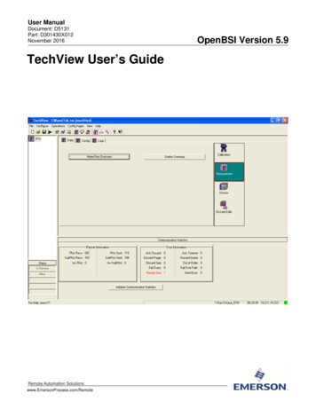
User ManualDocument: D5131Part: D301430X012November 2016TechView User’s GuideRemote Automation Solutionswww.EmersonProcess.com/RemoteOpenBSI Version 5.9
Application Safety Considerations Protecting Operating ProcessesA failure of this application – for whatever reason -- may leave an operating process withoutappropriate protection and could result in possible damage to property or injury to persons. To protectagainst this, you should review the need for additional backup equipment or provide alternate meansof protection (such as alarm devices, output limiting, fail-safe valves, relief valves, emergency shutoffs,emergency switches, etc.)CAUTIONWhen implementing control using this product, observe best industry practices as suggested by applicableand appropriate environmental, health, and safety organizations. While this product can be used as a safetycomponent in a system, it is NOT intended or designed to be the ONLY safety mechanism in that system.
TechView User’s GuideContentsChapter 1 – Introduction - What is TechView?1-1Chapter 2 – TechView Installation2-1Chapter 3 – Starting TechView and Establishing Communications3-13.13.23.3Starting Your Session: .3-1Establishing Communications .3-23.2.1 Communication Setup page - BSAP .3-23.2.2 Communication Setup page - IP .3-33.2.3 Advanced Communication Parameters – BSAP .3-43.2.4 Advanced Communication Parameters – IP .3-73.2.5 Node Setup .3-83.2.6 Calibration Setup .3-103.2.7 Transmitter Setup (Only Visible if using Remote Access) .3-13Signing On to the RTU .3-15Chapter 4 – Overview of TechView Functions4.14.24.34.44.54.6Chapter 5 – Calibration Overview5.15.25.35.45-1Why is Calibration Necessary? .5-1Calibration Concepts .5-1Before You Begin .5-3Equipment Required for Calibration .5-55.4.1 Equipment Required For Pressure Calibration .5-55.4.2 Equipment Required For Temperature Calibration .5-75.4.3 Equipment Required for Analog Output Calibration (3808 only).5-75.4.4 Entering Calibration Mode / Leaving Calibration Mode .5-7Chapter 6 – Calibrating the 3508 series TeleTrans Transmitter6.14-1Changing the Session Parameters You Entered .4-2Restarting the Session .4-3Saving Your Session File .4-3Copying Your Session to Another Session File Name .4-3Application Settings .4-34.4.1 Startup tab .4-44.4.2 Security tab .4-74.4.3 General tab .4-7Calibration and Verification Signals .4-84.5.1 Extended Verification .4-94.5.2 Changing the Name of a Transmitter .4-11Changing the Local Address / Group Number .4-114.6.1 Starting the Flash Configuration Utility.4-124.6.2 Show Firmware Version in Node .4-124.6.3 Writing an Audit Note .4-124.6.4 Viewing OpenBSI Workstation Communication Statistics .4-134.6.5 Deleting Historical Files from the RTU (Clear History) .4-136-1Calibration of Differential/Gage Pressure .6-1Issued Nov-2016Contentsiii
TechView User’s Guide6.26.3Calibration of Static Pressure . 6-3Calibration of RTD Temperature .6-5Chapter 7 – Calibrating the 3808 Transmitter7.17.27.37.4Calibration of Gage or Differential Pressure (3808-10A/3808-30A only). 7-1Calibration of Static Pressure (3808-30A ONLY) . 7-2Calibration of RTD Temperature .7-3Calibrating the Analog Output (Analog Pressure Transducer models ONLY) . 7-5Chapter 8 – Calibrating the 3530 TeleFlow-series Flow Computers8.18.28.38.48.58.68.79.88-1Calibration of Differential/Gage Pressure . 8-1Verification of Differential Pressure. 8-2Calibration of Static Pressure . 8-2Verification of Static Pressure . 8-3Calibration of RTD Temperature .8-48.5.1 Verification of RTD Temperature . 8-6Damping . 8-68.6.1 Configuring the Damping Time . 8-7Calibrating TeleRecorder Inputs (3530-45B/55B ONLY) . 8-78.7.1 Calibrating the Input . 8-8Chapter 9 – Calibrating the ControlWave EFM / GFC-CL /GFC/ XFC9.19.29.39.49.59.69.77-19-1Calibration of Differential/Gage Pressure . 9-1Verification of Differential/Gage Pressure . 9-2Calibration of Static Pressure . 9-4Verification of Static Pressure . 9-5Calibration of RTD Temperature .9-6Verification of Temperature . 9-9Damping . 9-119.7.1 Configuring the Damping Time . 9-11Orifice . 9-129.8.1 Specifying the Orifice Plate Size . 9-12Chapter 10 – Configuring and Calibrating the 4088B10-110.1 Configuring the 4088B . 10-110.1.1 DP/GP Pressure. 10-210.1.2 Static Pressure . 10-210.1.3 Temperature. 10-310.1.4 Serial Port Setup . 10-410.1.5 Transmitter Data . 10-510.1.6 RTD Coefficients . 10-610.2 Calibrating the 4088B. 10-610.2.1 Calibration of Gage or Differential Pressure . 10-710.2.2 Calibration of Static Pressure . 10-710.2.3 Calibration of RTD Temperature . 10-8Chapter 11 – Online Editing (ControlWave only)11-111.1 On-line Editing of Signal Lists . 11-111.2 On-line Editing of Archive Files . 11-411.2.1 Archive Fields. 11-611.2.2 Batch Editing of Archive Files . 11-7Chapter 12 – Device and Measurement GroupsivContents12-1Issued Nov-2016
TechView User’s GuideAppendix A -Initialization FilesA-1Creating an Advanced Interface Setup File for Storage at the RTU . A-2To create an Advanced Interface Setup Zip File for a custom application: . A-2AISF.TVS File Format . A-3Configuration Initialization (*.INI) Files (Platform-dependent) . A-5LISTS.INI . A-15TRANSLATION.INI Initialization File . A-16Notes about IP Address Formats in TVS Files . A-19IndexIssued Nov-2016IND-1Contentsv
This page is intentionally left blank
TechView User’s Guide (D5131)Chapter 1 – Introduction - What is TechView?TechView is a standalone software package that allows a technician to: Calibrate transmitter(s) either locally (bench configuration) or viacommunication with the transmitter’s master controller (RTU). Perform certain basic configuration operations on a controller, flowcomputer, or transmitter, such as changing the local address orEBSAP group number. Collect real-time or historical data from the controller, flowcomputer, or transmitter. Start other OpenBSI programs or utilities to perform other activities,such as the Flash Configuration utility. Perform on-line edits to signal lists, and to the structure of archivefiles in ControlWave-series controllers. (Requires 4.60 or newerControlWave firmware.)Typically, you install TechView software on a portable laptop computerto allow the technician to bring it to the site of the RTU/transmitter. Youcould also install it on a desktop computer in a lab for benchconfiguration of a transmitter.You can use TechView to calibrate the RTD temperature circuitry and/or the MVT/GPT pressure transducer for the following products: Issued Nov-20163508 TeleTrans Transmitter3808 MVT Transmitter (Firmware Version 1.5 or newer)3530-10B TeleFlow Electronic Gas Measurement Computer3530-20B TeleFlow Plus3
Once you have a session file saved, you can start TechView by standard Windows methods such as typing ‘TechView’ on the command line, followed by the path and name of the session file (excluding the TVS extension), or you can drag a TVS file icon onto a shortcut icon for the TechView application.