Transcription
Piping & Instrument DiagramsBarry M Barkel PE
Communication for Engineers VerbalAssignments, Instructions, updates WrittenReports, Procedures, Specifications MathematicalCalculations, data, Performance statistics SymbolicDesigns, Process Documentation
Drawings are Engineering’sINTERNATIONAL LANGUAGEengineers all over the world can understand them
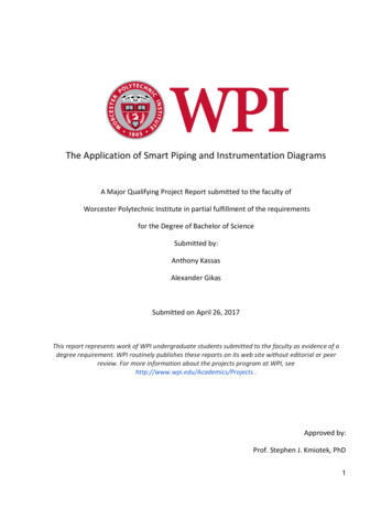
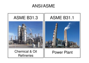
TYPES of DRAWINGS Process Flow Diagrams: What a Process Does Piping & Instrument Diagrams: How it works Layout Drawings: How it looks Mechanical Drawings: How to build itConstruction Drawings:
dwg1
Uses of P&IDs Develop Operational methodology Develop Safety Philosophy and Design Develop Control Philosophy Basis for Control Programming Communication Document for Project
Uses of P&IDs Serves as Design Basis for:Equipment DesignPiping DesignEstimatingPurchasing Used to evaluate construction progress Training basis for Operational Personnel
Characteristics of P&IDs Grouped by specific sections of the process Schematic; NOT a scaled layout Clear; uncluttered Systematic; uniform Usually confidential Revised often with Revisons clearly identified
Elements of a P&ID Equipment & valves identified Instrumentation type & location identified Path between instruments & control devices indicated Piping size and type identified for all lines
Identification of Equipment Identification by typew/ specific code designation.ie TKw/ a specific standardized shape Identification by numberw/ specific item number ie TK 101 Identification by namew/ what the unit is called. ie methanol tank
Valve Identification Identification by type
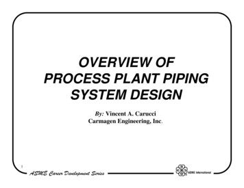
Instruments Instruments may be: Indicatorsor Part of a control system Instruments often have several components:sensing elementstransmitterscontrol elements
Some Instrument DesignationsP pressureT TemperatureF FlowL LevelI indicatorC controllerS switchE elementT transmitterG gage ISA designations usually used
Instrument ConfigurationTT1101PI106TE101
Control Paths Hardwired “Computer program”
Piping Designations Line Codes Spec breaks
Line Codes SizeServiceMat’l of Constr or Piping SpecInsulation amount and Spec
Pipe size“Nominal diameter”1”, 2 1/2”, 4” etc.
Pipe ServiceCoded to a designation shown on P&IDsExamples: Methanol- MeReactor Product Stream- RxP
Material of Construction GenericExamples- PVC316L S/S Company or Project SpecificationExamples- PP1( a specification covering the materials andjoining methods for PVC plastic pipe)
Insulation Code Thickness of insulation ( inches) Type or Insulation SpecificationExample- F ( fiberglass)- IN 9 ( Project Specification forCalcium Silicate System) Tracing CodeExamples- S (steam)E (electric)
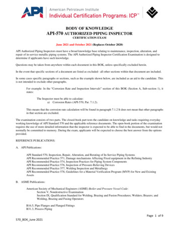
Total Line CodeExample2” dia., Type 304 s/s pipe in acetic acidreactor discharge service, insulated with1” of fiberglass insulation2”AARX-304S/S-1”F
Spec Breaks A Line /Code changes every time ANYELEMENT in the code changesIE3”AARX-304L S/S-1”F -- 3”AARX-304L S/Sat the point where the fluid has cooled enough toeliminate the insulation.3”AARX-304L S/S-1”F3”AARX-304L S/SSpec Breaks are shown as --------------]-------------
Notes on P&IDs Normally read LEFT to RIGHTTOP to BOTTOM The Stream No.s, Ts, Ps and Flowsfrom the PFD do NOT appear on aP& ID Equipment numbers are the same as onthe corresponding PFD
THANK YOUQs ?
Piping size and type identified for all lines. Identification of Equipment Identification by type w/ specific code designation.ie TK w/ a specific standardized shape Identification by number w/ specific item number ie TK 101 Identification by name w/ what the unit is called. ie methanol tank . Valve Identification Identification by type. Instruments Instruments may be .