Transcription
ProSAFE Plus Configuration UtilityUser ManualAugust 2016202-10524-06350 East Plumeria DriveSan Jose, CA 95134USA
NETGEAR ProSAFE Plus Configuration UtilitySupportThank you for purchasing this NETGEAR product. You can visit www.netgear.com/support to register your product, get help,access the latest downloads and user manuals, and join our community. We recommend that you use only official NETGEARsupport resources.ConformityFor the current EU Declaration of Conformity, visit http://kb.netgear.com/app/answers/detail/a id/11621.ComplianceFor regulatory compliance information, visit http://www.netgear.com/about/regulatory.See the regulatory compliance document before connecting the power supply.Trademarks NETGEAR, Inc., NETGEAR and the NETGEAR Logo are trademarks of NETGEAR, Inc. Any non-NETGEAR trademarks areused for reference purposes only.Revision HistoryPublication Part NumberPublish DateComments202-10524-06August 2016Revised the content entirely and updated the book format202-10524-05December 2012Updated the book format202-10524-04May 2012Added the LAG and registration features202-10524-03September 2010Added the multicast and IGMP snooping features202-10524-02February 2010Added support for multiple languages and the cable testing, ratelimiting, and broadcast filtering features202-10524-01September 2009First publication2
ContentsChapter 1Get StartedWhat Is the ProSAFE Plus Configuration Utility? . . . . . . . . . . . . . . . . . . . . . . . . . . 6Install the ProSAFE Plus Utility. . . . . . . . . . . . . . . . . . . . . . . . . . . . . . . . . . . . . . . . . . 6Access the ProSAFE Plus Utility and Your Switch . . . . . . . . . . . . . . . . . . . . . . . . . . 7Chapter 2Manage Network SettingsSpecify IP Address Settings for the Switch . . . . . . . . . . . . . . . . . . . . . . . . . . . . . .Manage Multicast Traffic With IGMP Snooping . . . . . . . . . . . . . . . . . . . . . . . . . .Customize IGMP Snooping . . . . . . . . . . . . . . . . . . . . . . . . . . . . . . . . . . . . . . . . .Specify a VLAN for IGMP Snooping. . . . . . . . . . . . . . . . . . . . . . . . . . . . . . . . . .Set Up Static Link Aggregation Groups . . . . . . . . . . . . . . . . . . . . . . . . . . . . . . . . .Chapter 3Optimize Performance With Quality of ServiceEnable 802.1p/DSCP-Based Quality of Service . . . . . . . . . . . . . . . . . . . . . . . . .Configure Port-Based Quality of Service . . . . . . . . . . . . . . . . . . . . . . . . . . . . . . .Set Up Rate Limiting . . . . . . . . . . . . . . . . . . . . . . . . . . . . . . . . . . . . . . . . . . . . . . . . .Set Up Broadcast Filtering . . . . . . . . . . . . . . . . . . . . . . . . . . . . . . . . . . . . . . . . . . . .Chapter 418192022Use VLANS for Traffic SegmentationVLAN Overview . . . . . . . . . . . . . . . . . . . . . . . . . . . . . . . . . . . . . . . . . . . . . . . . . . . . .Create Basic Port-Based VLANs . . . . . . . . . . . . . . . . . . . . . . . . . . . . . . . . . . . . . . .Assign Ports to Multiple Port-Based VLANs . . . . . . . . . . . . . . . . . . . . . . . . . . . . .Create 802.1Q-Based VLANs in a Basic Configuration. . . . . . . . . . . . . . . . . . . .Create 802.1Q-Based VLANs in an Advanced Configuration . . . . . . . . . . . . . .Add Tagged or Untagged Ports to an 802.1Q-Based VLAN. . . . . . . . . . . . . . . .Specify a Port PVID for an 802.1Q-Based VLAN . . . . . . . . . . . . . . . . . . . . . . . .Chapter 5111212131425252728303133Manage and Monitor the SwitchManage Flow Control . . . . . . . . . . . . . . . . . . . . . . . . . . . . . . . . . . . . . . . . . . . . . . . .Manage the Port Speed . . . . . . . . . . . . . . . . . . . . . . . . . . . . . . . . . . . . . . . . . . . . . .Enable Loop Detection . . . . . . . . . . . . . . . . . . . . . . . . . . . . . . . . . . . . . . . . . . . . . . .Manage Power Saving Options . . . . . . . . . . . . . . . . . . . . . . . . . . . . . . . . . . . . . . . .Change the Password . . . . . . . . . . . . . . . . . . . . . . . . . . . . . . . . . . . . . . . . . . . . . . . .Upgrade the Firmware . . . . . . . . . . . . . . . . . . . . . . . . . . . . . . . . . . . . . . . . . . . . . . .Reboot the Switch . . . . . . . . . . . . . . . . . . . . . . . . . . . . . . . . . . . . . . . . . . . . . . . . . . .Save the Switch Configuration . . . . . . . . . . . . . . . . . . . . . . . . . . . . . . . . . . . . . . . .Restore a Saved Switch Configuration . . . . . . . . . . . . . . . . . . . . . . . . . . . . . . . . . .3363738394041424243
NETGEAR ProSAFE Plus Configuration UtilityRestore Factory Default Settings . . . . . . . . . . . . . . . . . . . . . . . . . . . . . . . . . . . . . .Enable Port Mirroring . . . . . . . . . . . . . . . . . . . . . . . . . . . . . . . . . . . . . . . . . . . . . . . .View Switch Information . . . . . . . . . . . . . . . . . . . . . . . . . . . . . . . . . . . . . . . . . . . . .View the Port Statistics . . . . . . . . . . . . . . . . . . . . . . . . . . . . . . . . . . . . . . . . . . . . . .44454647Chapter 6 Diagnostics and TroubleshootingTest Cable Connections . . . . . . . . . . . . . . . . . . . . . . . . . . . . . . . . . . . . . . . . . . . . . . 49Resolve a Subnet Conflict to Access the Switch . . . . . . . . . . . . . . . . . . . . . . . . . . 50Uninstall the ProSAFE Plus Utility . . . . . . . . . . . . . . . . . . . . . . . . . . . . . . . . . . . . . . 504
1.1Get StartedThe NETGEAR ProSAFE Plus Configuration Utility runs on a Windows-based computer andlets you configure and manage ProSAFE Web Managed (Plus) Series Switches in your network.This chapter covers the following topics: What Is the ProSAFE Plus Configuration Utility? Install the ProSAFE Plus Utility Access the ProSAFE Plus Utility and Your SwitchNote: For more information about the topics covered in this manual, visit thesupport website at netgear.com/support.Note: New releases of the ProSAFE Plus Configuration Utility are madeavailable from time to time at downloadcenter.netgear.com.5
NETGEAR ProSAFE Plus Configuration UtilityWhat Is the ProSAFE Plus Configuration Utility?The ProSAFE Plus Configuration Utility, also referred to as the ProSAFE Plus Utility (or justthe utility), lets you discover and configure ProSAFE Web Managed (Plus) Series Switches(visit ) on your network.The utility runs on Windows-based computers. You can install the utility to customize andmanage one or more switches for your network. The utility is located on the resource CD thatcomes with a switch. You can also visit netgear.com/support/product/PCU to download thelatest version of the utility.Instead of using the ProSAFE Plus Utility, you can also access and configure a ProSAFEWeb Managed (Plus) Series Switch directly using a web browser and the switch’s webbrowser–based management interface. For more information, see the ProSAFE Gigabit WebManaged (Plus) Switches User Manual or a user manual that is specific to your switch model.You can download manuals by visiting downloadcenter.netgear.com.Some switches allow you to turn off the ability to manage them using the ProSAFE PlusUtility, only allowing them to be managed through the web browser–based managementinterface. If you do so, you can still use the ProSAFE Plus Utility to discover the switch in thenetwork and determine its IP address, but you can only use the web browser–basedmanagement interface to configure and manage the switch. You can reenable the fullcapability of the ProSAFE Plus Utility from the web browser–based management interface.Install the ProSAFE Plus UtilityYou can install the ProSAFE Plus Utility on any computer that runs a Windows operatingsystem (OS) and that is on the same network as the switches that you want to manage. If anearlier version of the utility is present on your computer, installing a newer version replacesthe older version. Newer versions of the utility are backward compatible and support allpreviously released ProSAFE Web Managed (Plus) Series Switches.Note: The ProSAFE Plus Utility requires Adobe Air. If you want to manage amodel FS116E or model JFS524E switch, the ProSAFE Plus Utilityalso requires WinPcap. If Adobe Air and WinPcap are not detectedduring ProSAFE Plus Utility installation, you are prompted to allowthem be installed.Get Started6
NETGEAR ProSAFE Plus Configuration Utility To install the utility from the resource CD:1. Insert the resource CD into a computer that is connected to the switch.The Resource CD page displays.Note: If the Resource CD page does not display, your computer’s Autorunfeature might be disabled. Enable the Autorun feature or use thecomputer’s file manager to navigate to the CD and double-click theutility’s .exe file.2. Click the Install ProSAFE Plus Utility link and follow the prompts to install the program.If your computer runs a Windows 7 OS, the utility is installed in the Program Files folder ofyour computer and a ProSAFE Plus Utility icon is placed on your desktop.If your computer runs a Windows 8 OS, Windows 8.1 OS, or Windows 10 OS, the utility isinstalled in the Program Files folder of your computer and a new tile is created.If your computer runs a Windows 10 OS, the utility is installed in the Program Files folderof your computer, a ProSAFE Plus Utility icon is placed on your desktop, and a new tileis created.3. If prompted, allow WinPcap and Adobe Air to be installed.4. Reboot your computer after installing the ProSAFE Plus Utility.Access the ProSAFE Plus Utility and Your SwitchFor easiest access, we recommend that you cable the switch to a network with a router orDHCP server that assigns IP addresses, power on the switch, and then use the computer onwhich the ProSAFE Plus Utility is installed and that is connected to the same network as theswitch.The ProSAFE Plus Utility automatically discovers any ProSAFE Web Managed (Plus)switches in your network. To configure the switch using the ProSAFE Plus Utility:1. Cable the switch to a network with a router or DHCP server that manages IP address.2. Power on the switch.The DHCP server assigns the switch an IP address.3. Connect your computer to the same network as the switch.You can use a WiFi or wired connection. The computer and the switch must be on thesame layer 2 network.4. Launch the ProSAFE Plus Utility using the desktop iconGet Started7or tile.
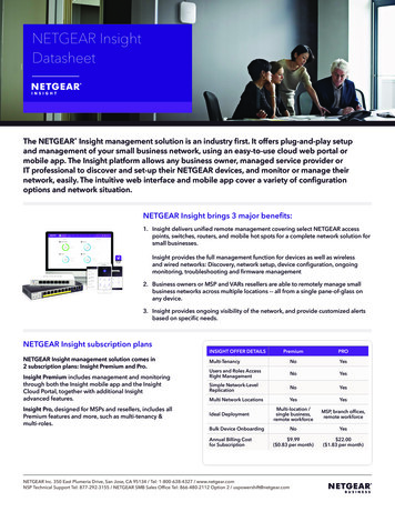
NETGEAR ProSAFE Plus Configuration UtilityThe Switch Selection page displays a list of Web Managed (Plus) switches that the utilitydiscovers on the local network.If the ProSAFE Plus Utility is unable to discover the switches in your network, make surethat your computer’s security software allows broadcast of UDP packets to go throughUDP remote and source (local and destination) ports 63321 through 63324.To allow this traffic, do one of the following: Create a rule in your computer’s security software. Temporarily disable the firewall, Internet security, antivirus programs, or all of theseprograms.5. To change the language, do the following:a. From the Select Language menu, select your language.A pop-up window displays.b. Click the Yes button.The utility relaunches.6. Select the ProSAFE Web Managed (Plus) switch that you want to configure.If you do not see the switch, click the REFRESH button.If the switch is connected to the Internet and you log in to the switch for the first time, theRegistration pop-up window displays. If this is not the first time that you log in, theRegistration pop-up window might display, depending on the selection that you made inthe Registration pop-up window during the previous session.7. If the Registration pop-up window displays, select one of the following radio buttons: Turn Off. The Registration pop-up window closes and does not display again.However, if you restore the switch to factory default settings, the pop-up windowdisplays again 24 hours after the restoration.Get Started8
NETGEAR ProSAFE Plus Configuration Utility Remind Me Later. The Registration pop-up window closes. After 24 hours, theRegistration pop-up window might display again. Register Now. If the switch is connected to the Internet connection, the NETGEARwebsite displays and you can register your product.8. When prompted, enter the password.The default password is password.The Switch Information page displays.9. Use the utility to configure the switch settings.Specific configuration procedures are described in this manual.10. If you temporarily disabled the firewall, Internet security, antivirus programs, or all ofthese programs, return them to their usual settings when you are finished with theconfiguration.Get Started9
2.Manage Network SettingsThis chapter covers the following topics: Specify IP Address Settings for the Switch Manage Multicast Traffic With IGMP Snooping Set Up Static Link Aggregation Groups102
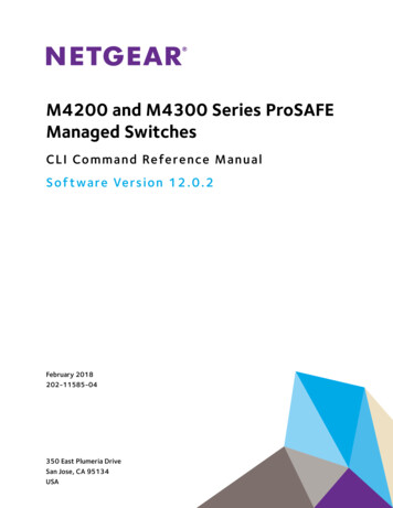
NETGEAR ProSAFE Plus Configuration UtilitySpecify IP Address Settings for the SwitchBy default, the switch IP address works as follows: If you cable the switch to a network with a DHCP server before you power on the switch,the DHCP server assigns an IP address to the switch when the switch is powered on. If you power on the switch when it is not connected to a network with a DHCP server, theswitch uses its default IP address, which is 192.168.0.239.You can disable the DHCP mode in the switch and enter static IP address and subnetmask values for the switch as well as the address of the gateway device used by theswitch. To specify IP address settings for a switch:1. Connect your computer to the same network as the switch.You can use a WiFi or wired network connection, or connect directly to a switch that isoff-network using an Ethernet cable.2. Launch the ProSAFE Plus Utility using the desktop icon or tile.The Switch Selection page displays a list of Web Managed (Plus) switches that itdiscovers on the local network.3. Select the switch.If you do not see the switch, click the REFRESH button.4. Click the IP SETTING button.Note: To navigate to this page, select Network, select the switch, and clickthe IP SETTING button.5. In the DHCP Mode menu, select Disable.The IP Address, Subnet Mask, and Gateway Address fields are enabled.6. Enter the IP address, subnet mask, and if available, the gateway address.7. Enter the switch’s password in the Password field.Manage Network Settings11
NETGEAR ProSAFE Plus Configuration UtilityThe switch’s default password is password.8. Click the APPLY button.Your settings are saved.Manage Multicast Traffic With IGMP SnoopingInternet Group Management Protocol (IGMP) snooping allows a switch to forward multicasttraffic intelligently on the switch. Multicast IP traffic is traffic that is destined to a host group.Host groups are identified by class D IP addresses, which range from 224.0.0.0 to239.255.255.255. Based on the IGMP query and report messages, the switch forwards trafficonly to the ports that request the multicast traffic. This feature prevents the switch frombroadcasting the traffic to all ports and possibly affecting network performance.The switch maintains a map that shows which links need which IP multicast streams. Theswitch forwards multicast traffic only to the links that requested them and cuts multicast trafficfrom links that do not contain a multicast listener. Essentially, IGMP snooping helps optimizemulticast performance at Layer 2 and is especially useful for bandwidth-intensive IP multicastapplications such as IPTV.Customize IGMP SnoopingBy default, IGMP snooping is enabled. You can customize the settings for your network. To customize IGMP snooping:1. Connect your computer to the same network as the switch.You can use a WiFi or wired network connection, or connect directly to a switch that isoff-network using an Ethernet cable.2. Launch the ProSAFE Plus Utility using the desktop icon or tile.The Switch Selection page displays a list of Web Managed (Plus) switches that itdiscovers on the local network.3. Select the switch.If you do not see the switch, click the REFRESH button.4. Click the APPLY button.You are asked to enter the password for the switch.5. Enter the switch’s password in the password field.The switch’s default password is password.The Switch Status page displays.6. Select System Multicast.Manage Network Settings12
NETGEAR ProSAFE Plus Configuration Utility7. Select the IGMP Snooping Status Enable radio button.8. (Optional) Select the Validate IGMPv3 IP header Enable radio button.Some network devices might not conform to the IGMPv3 standard. When the ValidateIGMPv3 IP header option is enabled, IGMP messages are required to include TTL 1,ToS Byte 0xC0 (Internetwork Control), and the router alert IP option (9404) must be set.Otherwise, the packets are ignored.9. (Optional) Select the Block Unknown MultiCast Address Enable radio button.When this feature is enabled, multicast packets are forwarded only to the ports that are inthe multicast group learned from IGMP snooping. All unknown multicast packets aredropped.10. (Optional, for some models only) Select an option from the IGMP Snooping Static RouterPort menu.You can select a port to be the dedicated IGMP snooping static router port if no IGMPquery exists in the network for the switch to discover the router port dynamically. After aport is selected as the static router port, all IGMP Join and Leave reports are forwarded tothe port.11. Click the APPLY button.Your settings are saved.Specify a VLAN for IGMP SnoopingYou can specify a VLAN for IGMP snooping only if you enabled port-based or 802.1Q-basedVLANs (see Chapter 4, Use VLANS for Traffic Segmentation). To specify a VLAN for IGMP snooping:1. Connect your computer to the same network as the switch.You can use a WiFi or wired network connection, or connect directly to a switch that isoff-network using an Ethernet cable.2. Launch the ProSAFE Plus Utility using the desktop icon or tile.The Switch Selection page displays a list of Web Managed (Plus) switches that itdiscovers on the local network.Manage Network Settings13
NETGEAR ProSAFE Plus Configuration Utility3. Select the switch.If you do not see the switch, click the REFRESH button.4. Click the APPLY button.You are asked to enter the password for the switch.5. Enter the switch’s password in the password field.The switch’s default password is password.The Switch Status page displays.6. Select System Multicast.The previous figure is an example. Your switch might support more or less VLANs forIGMP snooping.7. Make sure that the IGMP Snooping Status Enable radio button is selected.8. In the VLAN ID Enabled for IGMP Snooping field, enter the ID of the VLAN.By default, if you enable IGMP snooping, snooping occurs on VLAN 1. However, you canenable snooping on any VLAN: For port-based VLANs, you can enter a VLAN ID from 1 to the maximum number thatyou switch supports (5, 8, 16, or 24). For 802.1Q-based VLANs, you can enter a VLAN ID from 1 to 4094.9. Click the APPLY button.Your settings are saved.Set Up Static Link Aggregation GroupsLink aggregation groups (LAGs) allow you to combine multiple Ethernet links into a singlelogical link. Network devices treat the aggregation as if it were a single link, which increasesfault tolerance and load sharing. The number of LAGs that the switch supports depends onthe model. Configure LAG membership before you enable the LAG.Manage Network Settings14
NETGEAR ProSAFE Plus Configuration UtilityNote: The switch does not support IEEE 802.3ad Link Aggregation or LinkAggregation Control Protocol (LACP) groups. The switch supportsmanual static LAGs only.You must set up LAG membership before you can enable LAGs. To specify LAG membership and enable a LAG:1. Connect your computer to the same network as the switch.You can use a WiFi or wired network connection, or connect directly to a switch that isoff-network using an Ethernet cable.2. Launch the ProSAFE Plus Utility using the desktop icon or tile.The Switch Selection page displays a list of Web Managed (Plus) switches that itdiscovers on the local network.3. Select the switch.If you do not see the switch, click the REFRESH button.4. Click the APPLY button.You are asked to enter the password for the switch.5. Enter the switch’s password in the password field.The switch’s default password is password.The Switch Status page displays.6. Select System LAG LAG Membership.The previous figure is an example. Your switch might provide a larger number of ports.7. In the LAG ID menu, select the LAG ID.The number of LAGs that the switch supports depends on the model.8. Select the ports for the LAG by selecting the associated check boxes under the portnumbers.A LAG consists of at least two ports.9. Click the APPLY button.Your settings are saved.10. Select System LAG.Manage Network Settings15
NETGEAR ProSAFE Plus Configuration Utility11. Select the ID of the LAG for which you just set up the port membership.12. In the Admin Mode menu, select Enable.13. Click the APPLY button.Your settings are saved.Manage Network Settings16
3.Optimize Performance WithQuality of ServiceThis chapter covers the following topics: Enable 802.1p/DSCP-Based Quality of Service Configure Port-Based Quality of Service Set Up Rate Limiting Set Up Broadcast Filtering173
NETGEAR ProSAFE Plus Configuration UtilityEnable 802.1p/DSCP-Based Quality of Service802.1p/DSCP-based priority uses a field in the data packet header that identifies the class ofdata in the packet (for example, voice or video). When 802.1p/DSCP-based priority is used,the switch reads information in the packet header to determine the priority to assign to thepacket. The switch reads both 802.1p tag information and DSCP/ToS tag information. If aningress packet contains both an 802.1p tag and a DSCP/ToS tag, the switch givesprecedence to the 802.1p tag.All ports on the switch check the packet header and transmit the packet with a prioritydetermined by the packet content.This feature is enabled by default. To enable 802.1p/DSCP-based QoS:1. Connect your computer to the same network as the switch.You can use a WiFi or wired connection.2. Launch the ProSAFE Plus Utility using the desktop icon or tile.The Switch Selection page displays a list of Web Managed (Plus) switches that itdiscovers on the local network.3. Select the switch.If you do not see the switch, click the REFRESH button.4. Click the APPLY button.You are asked to enter the password for the switch.5. Enter the switch’s password in the password field.The switch’s default password is password.The Switch Status page displays.6. Select QoS.The Quality of Service page displays.7. Select the 802.1p/DSCP Based radio button.A pop-up window opens, informing you that the current QoS settings will be lost.8. Click the Yes button.The pop-up window closes.9. Click the APPLY button.Your settings are saved. Data is now processed based on 802.1p priority tags in the data.Optimize Performance With Quality of Service18
NETGEAR ProSAFE Plus Configuration UtilityConfigure Port-Based Quality of ServiceYou can assign a priority to all data passing through a particular port. Data with a higherpriority is transmitted faster. If packets arrive at several ports at the same time, the portsconfigured as higher priority transmit their packets first. You must determine which ports willcarry delay-sensitive data. To configure port-based QoS:1. Connect your computer to the same network as the switch.You can use a WiFi or wired network connection, or connect directly to a switch that isoff-network using an Ethernet cable.2. Launch the ProSAFE Plus Utility using the desktop icon or tile.The Switch Selection page displays a list of Web Managed (Plus) switches that itdiscovers on the local network.3. Select the switch.If you do not see the switch, click the REFRESH button.4. Click the APPLY button.You are asked to enter the password for the switch.5. Enter the switch’s password in the password field.The switch’s default password is password.The Switch Status page displays.6. Select QoS.The Quality of Service page displays.7. If this is the first time that you are setting up port-based QoS, select the Port Based radiobutton and continue with Step 8.Otherwise, see Step 9.A pop-up window opens, informing you that the current QoS settings will be lost.8. Click the Yes button.The pop-up window closes and the port priority options display.Optimize Performance With Quality of Service19
NETGEAR ProSAFE Plus Configuration UtilityThe previous figure is an example. Your switch might provide more or less ports. The802.1p/DSCP-based radio button is not supported on all models and therefore might notshow on the page.9. To set the port priority for one or more ports, do the following:a. Select one or more ports.b. In the Priority section, select the priority by moving the slider.c. Click the APPLY button.Your settings are saved. The same priority is applied to all ports that you selected.10. To set a different port priority for one or more other ports, repeat Step 9.Set Up Rate LimitingYou can limit the rate at which the switch accepts incoming data and the rate that itretransmits outgoing data. The rate choices vary depending on the switch model.Rate limiting can be set for a port in addition to other QoS settings. If the port rate limit is set,the switch restricts the acceptance or retransmission of data to the values configured. To set up rate limiting:1. Connect your computer to the same network as the switch.You can use a WiFi or wired network connection, or connect directly to a switch that isoff-network using an Ethernet cable.2. Launch the ProSAFE Plus Utility using the desktop icon or tile.Optimize Performance With Quality of Service20
NETGEAR ProSAFE Plus Configuration UtilityThe Switch Selection page displays a list of Web Managed (Plus) switches that itdiscovers on the local network.3. Select the switch.If you do not see the switch, click the REFRESH button.4. Click the APPLY button.You are asked to enter the password for the switch.5. Enter the switch’s password in the password field.The switch’s default password is password.The Switch Status page displays.6. Select QoS Rate Limit.The previous figure is an example. Your switch might provide more or less ports.7. Select one or more ports.8. Set the ingress (incoming) and egress (outgoing) traffic rates by doing the following:a. Select one or more ports.b. In the Ingress Rate menu, select the maximum rate.The rate that you can set depends on the switch model. By default, no limit is set.c. In the Egress Rate menu, select the maximum rate.The rate that you can set depends on the switch model. By default, no limit is set.d. Click the APPLY button.Your settings are saved.9. To set different rates for one or more other ports, repeat Step 8.Optimize Performance With Quality of Service21
NETGEAR ProSAFE Plus Configuration UtilitySet Up Broadcast FilteringYou can configure the switch to block broadcast storms (massive transmission of broadcastpackets forwarded to every port on the same VLAN). If they are not blocked, broadcast stormpackets can delay or halt the transmission of other data. Some switches allow you to select astorm control rate for each port. Others assign a predetermined storm control rate for all portson the switch.If broadcast traffic on any port exceeds the threshold that you set, the switch temporarilyblocks (discards) the broadcast traffic. To set up broadcast filtering:1. Connect your computer to the same network as the switch.You can use a WiFi or wired network connection, or connect directly to a switch that isoff-network using an Ethernet cable.2. Launch the ProSAFE Plus Utility using the desktop icon or tile.The Switch Selection page displays a list of Web Managed (Plus) switches that itdiscovers on the local network.3. Select the switch.If you do not see the switch, click the REFRESH button.4. Click the APPLY button.You are asked to enter the password for the switch.5. Enter the switch’s password in the password field.The switch’s default password is password.The Switch Status page displays.6. Select QoS Broadcast Filtering.The Broadcast Filtering page displays.7. If this is the first time that you are setting up broadcast filtering, select the Enable radiobutton and continue with Step 8.Otherwise, see Step 9.8. Click the Apply button.Your settings are saved and the Storm control rate table displays.Optimize Performance With Quality of Service22
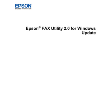
NETGEAR ProSAFE Plus Configuration UtilityThe previous figure is an example. Your switch might provide more or less ports.9. Set the storm control rate by doing the following:a. Select one or more ports.b. In the Storm control rate menu, select the maximum rate.You can set a rate from 512 Kbps to 512 Mbps. By default, no limit is set.c. Click the APPLY button.Your settings are saved.10. To set a different rate for one or more other ports, repeat Step 9.Optimize Performance With Quality of Service23
4.Use VLANS for TrafficSegmentationThis chapter covers the following topics: VLAN Overview Create Basic Port-Based VLANs Assign Ports to Multiple Port-Based VLANs Create 802.1Q-Based VLANs in a Basic Configuration Create 802.1Q-Based VLANs in an Advanced Configuration Add Tagged or Untagged Ports to an 802.1Q-Based VLAN Specify a Port PVID for an 802.1Q-Based VLAN244
NETGEAR ProSAFE Plus Configuration UtilityVLAN OverviewVirtual LANs (VLANs) are made up of networked devices that are grouped logically intoseparate networks. You can group ports on a switch to create a virtual network made up ofthe devices connected to the ports.Ports can be grouped in VLANs using port-based or 802.1Q criteria: Port-based VLANs. Assign ports to virtual networks. Ports with the same VLAN ID areplaced in the same VLAN. This feature provides an easy way to partition a network intoprivate subnetworks. 802.1Q VLANs. Create virtual networks using the IEEE 802.1Q standard. 802.1Q uses aVLAN tagging system to determine which VLAN an Eth
Instead of using the ProSAFE Plus Utility, you can also access and configure a ProSAFE Web Managed (Plus) Series Switch directly using a web browser and the switch's web browser-based management interface. For more information, see the ProSAFE Gigabit Web Managed (Plus) Switches User Manual or a user manual that is specific to your switch .