Transcription
General DisclaimerOne or more of the Following Statements may affect this DocumentThis document has been reproduced from the best copy furnished by theorganizational source. It is being released in the interest of making available asmuch information as possible.This document may contain data, which exceeds the sheet parameters. It wasfurnished in this condition by the organizational source and is the best copyavailable.This document may contain tone-on-tone or color graphs, charts and/or pictures,which have been reproduced in black and white.This document is paginated as submitted by the original source.Portions of this document are not fully legible due to the historical nature of someof the material. However, it is the best reproduction available from the originalsubmission.Produced by the NASA Center for Aerospace Information (CASI)
CPC 95{273 - ?PHASE 2 OF THE ARRAY AUTGMATED AS§E LLY TASKFOR THE LOW COST SOLAR ARRAY PROJECTR. B. Campbell, P. Rai-Choudhury, E. J. Seman,A. Rohatgi, J. R. Davis, J. W. Ostronki andR. E. StapletonQuar,:erly Report No. 7April1979 - June 30, 1979September 5, 1979Contract No. 954873This work was perfo need for the Jet Propulsion Laboratory,California Institute of Technology, under NASA ContractNAS7-100 for the U. S. Department of Energy, Division ofSolar Energy.The JPL Low Co;;t Solar Array Project is funded by DOEand forms part of the DOE Photovoltaic Conversion Programto initiate a major effort towards the development oflow cost solar arrays.P1( 14ASA-CP-162131)PHASE 2 OF THF, ARRAYA' 1T0rAT r-D ASSEMBLY TASK FOR T H7 LOW CnSTSOUP A pT AY PRO.IFCT OnartPrly Peport, 1N-70-33569Anr. - 30 Jun. 1974 (Westinghouse ResearchUnclasand)26 o "C A03/ 77F A01CSCG 10A G3/44 15937Iv Vz.cC "Jart.PiIWest ;nghouse R&D Centerg 1310 Beulah RoadPittsburgh. Pennsylvania 1535E
PHASE 2 OF THE ARRAY AUTOMATED ASSEMBLY TASKFOR THE LOW COST SOLAR ARRAY PROJECTR. B. Campbell, P. Rai-Choudhury, E. J. Seman,A. Rohatgi, J. R. Davis, J. W. Ostroski andR. E. StapletonQuarterly Report No. 7Lpril 1, 1979 - June 30, 1979September 5, 1979Contract- No. 954873This work was performed for the Jet Propulsion Laboratory,California Institute of Technology, under NASA ContractNAS7-100 for the U. S. Department of Energy, Division ofSolar Energy,The JPL Low Cost Solar Array Project is funded by DOEand forms part of the DOE Photovoltaic Conversion Programto initiate a major effort towards the development oflow cost p olar arrays.Westinghouse R&D Center 1310 Beulah RoadPittsburgh. Pennsylvania 152356 .
TECHNICAL CONTENT STATEMENTThis report was prepared as an account of work sponsored bythe United States Government. Neither the United Otatcs nor the UnitedStates Department of Energy, no: any of their employees, nor any of theircontractors, sub-contractors, or their employees, makes any warranties,c:cpress :r implied, or assumes any legal liability or responsibilityfor tho accuracy, completeness or usefulness of any information, arparatus, product or process disclosed, or represents that its use wouldnot infringe privately owned rights.NEW TECHNOLOGY1No new technology is reportable for the period covered by thisreport.C? ,;L pAfr l3jpoop141fr-i
TABLE OF CONTENTSList of Figures . . . . . . . . . . . . . . . . . . . . . . . . .iii. . . . . . . . . . . . . . . . . . . . . . . . .ivList of Tables1.Summary .2.Introduction3.Technical Discussion3.1. .1. . . . . . . . . . . . . . . . . . . . . . . .1. . . . . . . . . . . . . . . . . . . . . .Aluminum Back Surface Field Studies. . . . . . . . . . . . . . . . . .3.1.1Introduction3.1.23.1.3Silk Screened "AMPAL" Paste .Front Surface Protection . . .333. . . . . . .46. .7. .11. . . . . . . . . . . . . . . . . .113.2Electroless Plated Contacts.3.3Ultrasonic Bonding of Cell onic Bonding to Aluminum . . . . . . . .Module Fabrication Using Ultrasonic Bonding . .11it.13. . . . . . . . . . . . . . . . . . . . .131515194.Conclusions . . . . . . . . . . . . . . . . . . . . . . . . .195.Program Status203.4Process Sequence and Cost Analysis .3.4.13.4.23.4.33.4.4!5.15.26.Process Sequence. . . .Cells Produced by ProcessSAMICS Cost Analysis. .Costs Used in Format A's. . . . . . .Sequence. . . . . . . . . . . . . . . . . . . . . . . . . . . . . . .Present Status . .Future Work . . .Acknowledgements. . . . . . . . . . . . . . . . .2020. . . . . . . . . . . . . . . . . . . . . .20G.3II1TG PAGE BEAM N0Z1 FZNWiiiL. '.N h YiisawM}e .FMr. . Vmm h n.avc . . .
.'.i'i'a RESLIST F0Fig - 1 Efficiency Distribution of Float Zone Silicon SolarCellsSputtered and Silk Screened AL BSF,Fig. 2 Efficiency Distribution of Dendritic Web Solar CellsSputtered and Silk Screened AL BSFiv
LIST OF TABLESTable 1 Cells with AL BSF Produced by Alloying Silk Screened"AMPAL" Paste.Table 2 AL Back Surface Field Results (Average Values).Table 3 Parameters of Cells Fabricated Using Modified ElectrolessPlating for Contacts.Table 4 Ultrasonic Bonding to Aluminum.Table 5 Pull Test Data.Table 6 Westinghouse Process Sequence Coss.4.v
1.SMIRARYTwo process specifications supplied by other contractors havebeen tested. The Al Silk Screening Process by Spectrolab resulted, incells comparable to those from sputteredPL. The electroless platingof contacts specification supplied by Motorola could be used only withextensive modificatic.:. Several experiments suggest that there is somedegradation of the front j unction during the Al SSF fabrication. Arevised process sequence has been defined which incorporates Al BSFformation. A WHCS cost analysis of this process yielded a selling priceof 0.75/watt peak in 1980 .2.INTRODUCTIONThe major objective of this program is to define and verify aprocess sequence for the fabrication of solar cell modules from dendriticweb silico[i. Another objective is the development of key process steps.The process sequence and the individual steps must be amenable to automation and low cost manufacturing methods so that the target sellingprice of 0.70/watt peak (1980 in 1986) can be achieved.Pack the pp junction in an n pp cell)surface(i.e.,fields are incorporated into solar cells to enhance the open circuit voltage andthe short circuit current and thus improve the efficiency. The backsurface field operates by decoupling the high carrier recombinationvelocity region of the ohmic back surface from the bulk of the cell.enhancement haveocbeen prepared by alloying in a deposited Al layer from a deep, (8-10 pm)The back surface field cells which show the largest Vabrupt p region.In our studies of the Al SSF's we have selected sputtering asthe best technique for depositing the aluminum. The sputtered Al layersare of high purity, very adherent to the Si surface, and when alloyed
in, they form uniform p layers. Another method for depositing thealuminum is by silk screening an Al paste. This method has the advantageof lower initial capital inves anent, but the overall cost and reliabilitymust be determined. During this period we tested a Process Specificationsupplied by Spectrolab which uses an AMPAL aluminum powder. Followingthis procedure Al layers were screened onto float zone Si wafers anddendritic web silicon strips and alloyed in following their temperaturecycle. (The dendrites on the web samples were removed before silkscreening.) The cells fabricated in this way were equal in performanceto the cells with sputtered Al BSF's. However, in our process sequence,we have retained sputtering as the preferred technique, since specialmachinery would be required to silk screen between the dendrites. In ourprocess sequence, the dendrites are left on the cells throughout muchof the processing to maintain strength and reduce breakage loss.Our results with all the Al BSF techniques have shown Vocenhancement up to 0.585V. however, the physical parameters of the BSF(e.g. p width, surface concentration, junction gradient etc.) indicateshould be at least 20 mV higher. it was postulated that duringocthe BSF formation the front junction, which also effects the Voc, mightthat Vbe degraded. Several experiments showed that some front surface protectionwas required, with the best resultE occurring when the phosphorous glasswas left on the n surface.A totally plated contact system would conceivably be less expensive than an evaporated and electroplated system. Using a ProcessSpecification supplied by Motorola, we attempted to use this technique inour process sequence. The process involves the electroless depositionof Pd and Ni followed by the build up of a conductive layer (solder inthe Motorola process). Several tests showed that it was necessary tomodify the process significantly since the acidic rinses attached the ARcoating. (They would not lCtack the Si 3 N 4 coating used by Motorola.)Even with these modificaticas, the cell performance was significantlylower than cells produced by the baseline evaporated Ti I'd electroplatedAg system. Based on these data, it was decided that this process was notimmediately applicable to our process sequence.2I f. 1: . . .wwu M-. y.'.W r 3v ]:u.liud.nn . rve.' . . . -::.
xThe ultrasonic bonding of interconnect straps has severaladvantages in that no corrosive fluxes are used and there is no excessivebuild-up of metal in the contact area. A matrix has been defined wherefor given values of power, time and force, good bonds are achieved. Thesematrices have been developed for copper and aluminum interconnect strapsto silver and copper contacts. A similar schedule has been studied for Aland Cu straps to the Al back contact, bit the results are less reproducible.Several small mechanical panels have been fabricated using ultrasonicbonding.The process sequence previously defined has been revised byusing an Al BSF to replace the boron BSF. This simplified several of thesub-processes and decreased the total commodities cost. Using SAMICSmethodology the selling price of a dendritic web solar panel was 0.75/wattpeak(1980 in 1986).3. TECHNICAL RESULTS3.1 Aluminum Back Surface Field ;BSF) Studies3.1.1 IntroductionThe high-low junction at the back of an n p cell resultsin enhanced open circuit voltage and short circuit current. These backsurface fields (p regions) are produced either by a boron diffusion or,preferably, by liquid phase epitaxial growth from Al-Si alloy.In previous work we have shown that the aluminum used for theAl BSF may be deposited on the silicon surface by either sputtering ora silk screening process. The former, however, is preferred becausesilk screening the silicon between the dendrities involves complicatedequipment. The deposited aluminum is alloyed into the silicon by a shortheating cycle of one minute at850 C.Open circuit voltage enhancementof up to 50 mV is noted after the back surface field preparation withmaximum V oc 's on float zone silicon being 0.59V.3iJ
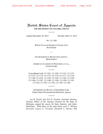
Piring this period, experiments were carried out to verify theSpectrolab Process Sequence using a silk screen Al paste and to investigatepossible reasons for the open cirr"i.t voltage not exceeding 0.6V.3.1.2 Silk Screened "ARPAL" PasteAl BSF cells have been fabricated by alloying in a silk*screened Al paste. The paste was prepared using AMPAL powder and theSpectralab Process Specification. The paste was applied using a 200 wire/inch stainless steel ;ereL, with 0.001" wire (open area of 0.004" x 0.004").After the Al paste was applied it was dried at 200 C for 15 minutes andthen alloyed in an RF heated furnace rt 850 C in H 2 or in a resistanceheated furnace at 850 C in N2.The silk-screened samples did not show any excessive bubblingor lifting of the Al layer during alloying as was noted with the evaporatedmaterial and some of the previous samples using other pastes. In Loththe resistance heated furnace and in the RF furnace, the melted Al on theback surface after alloying was sufficiently unoxidized, so that furthermetallization was not required co form a back contact. There was, however, sonic warping of the cell structure after th.: cloying. This warpage,due to the thick Al, meant the metal must be removed to relieve the stress.In several cases this warpage was sufficiently bad to crack the silicon.This could indicate that large area s reen printed devices may be difficultto fabricate by this process due to warpage and breakage.Table 1 shows the cell data for this experiment. All dendriticweb samples were from web crystal 14-141-1.4. The first two processses(1 and 2) compare slow cooled and normal cooled web samples alloyed ii, anRF furnace. The lifetime of the slow cooled material is about doublethat of the normally cooled, and this effect is mirrored in the shortcircuit current. The low efficiency of the fast cooled materiaL is dueto both the low IEL'and fill factor,AMPAL-631 powder - manufactured by Atmomized Metal Powders, Inc.,Flemington, NJ 08822.4
"rbu3NVl.O( 1OawFaauiwFONrw 1 1V 7 :3yPrn.cw ,. v.nC41401NOWu.-I.7wG o a{ QC7A00WnaOOu)Ot"1n jNCl) )U nvi„ 6INUL) NEiOuxc.m00 Cl) W OInoC'n3. v ay00UVO.-1H oUnaw 8v07 140dUuwotiI tUHWoN3uc,wNxIiou toyVO3Wco OS co V)v.". 00r-1Nf 1u Vw3I1I rl V.a WW V)S Wto oN 31W 00vUnuOw :-IWd3C: O HI 14 '1 uv) u o0ONdW M CO' S.-.mv. u . . . u na.li wdu.CrSP TdVR1t1WK.T? vm a .-. . . .is{
KiProcess 3 samples are controls and are fabricated on the sameweb crystal with the Al BSF produced by alloying a sputtered Al laver.Process 4 samples are also controls and are boron BSF cells produced bythe standard qualification process. Process 2 compares favorably withthese control samples.Process 5 samples are fabricated on float zone Si with the BSFproduced by alloying in the silk screened AMPAL paste. These results areto be compared with Process 6, which are FZ silicon cells with alloyedin sputtered Al layers. TLe loss of lifetime in the silk-screened FZcell (20 psec to 13 usec) may be due to some lifetime killing impurity,since all control ,iamples ware reacted at the same time as the experimental samples. Tne effect of the lifetime loss is noted in both Isr.and n for the cells in Process 6.The data indicate that Al BSF cells can be fabricated usingsilk screened "AMPAL" paste which are essentially e q ual to the sputteredAl process.The open circuit voltages noted in Table l are lower than thatgenerally reported for Al back surface fields. This lower value cannotgenerally be explained in terms of a too shallow p layer.The measured value; of the OCD lifetime and the short circuitcurrent, while not as high as expected for an Al BSF, do indicate anoperational back surface fieltHowever, the open circuit voltage isalso controlled by the front junction, and it is po.;sible that the frontjunction was degraded due to the fabrication of the Al BSF.3.1.3 Front Surface ProtectionAs noted in the previous section, the enhancement of theopen circuit voltage of Al BSF cells was less than expected for the notedcell lifetime and p profile.In an effort todetermine ifa small amount of aluminum wascontaminating the front junction, either during aluminum application oralloying, several experiments were carried out in which the front surface6f:
was protected, and an experiment in which the n layer was diffused inafter the p layer was prepared. These results, as well as the experimental conditions are given in Table 2. The data given are the averagesof 8 - 16 cells for each treatment. In all cases the p layer was preparedby alloying in a s lk-screened layer of AMPAL 0631 paste (as describedearlier). The penetration of the p layer was 6 - 8 um.The samples, in which the phosphorous glass diffusint sourcewas in place during the alloying, gave uniformly superior results. Treatment 03 (n layer formed after p layer) was the poorest and these resultsmay be due to a grading of the p junction during the 850 C diffusion tofor the n layer.Treatment O1 (top surface protected by Si0 2 ) produced cellswhich were also considerably poorer than the cells fabricated with thephosphorous glass protection.Alt .r gh not conclusive, these data do suggest that there issome effec. on the top surface (i.e. top n p junction) during the BSFformation.It should also be noted that even in the best case (Treatment 02)where the cells have a 24 psec lifetime and a p layer of 5 pm, the Vocis relatively low for an Al BSF.This phase of the program is now being discontinued. We willcontinue to study possible reasons for the lack of V oc enhancement oninternal funded programs.3.2 Ele ctroless P lated ContactsA total plated system for contacts may have certain costbenefits, specifically, lower capital costs as compared to an evaporated(or sputtered; plus plated system.In the last quarterly report on this program, initial experimentswere carried out using the Process Specification supplied by Motorola.In these first experiments it was found necessary to modify the Motorolaprocess since the e'ches and rinses called for in the specification usedtHF which attached the antireflection coating. (This is not a problem inr71
TABLE 2Al BACK SURFACE FIELD RESULTS (AVERAGE VALUES)(Silk Screened AMPAL - #631 - 85G C Drive 430.96.540.73012.912Isc(mA)Voc(V)1. Si0 on n side30.962. Phos glasson r.TOCD(u zc)side3. p layerf rmed beforen layerNotesTreatment 1 - Phos. glass removed after POC1 3 diffusion; Si0 2 appliedto one n side to protect surface from Al. Al driventhrough n layer.Treatment 2 - Phos. glass removed from one side; left on one n sidet protect surface from Al. Al driven through cleanedn layer.Treatment 3 - Al driven intocrystal; excess Al removed and n diffusioncarried out. p surface recontacted with Ti Pd Ag.Measured at AM-1; 91.6 MW/cm 2 - AR coatedI I:8
the Motorola process sequence since they use silicon nitride as an ARcoating which is not easily attached by the rinses. The AR coating inour process sequence is a mixed Ti0,) /Si0 2 system which is attached by HF).It, therefore, became necessary to reduce the rinsing time in the ]IFsolutions to preserve tho integrity of the AR coating.In these initial experiments, the yield of testable cells wassmall. These data, however, indicated that there was some degradation incell parameters using plated contacts as compared to cells on the sameweb crystal with normal processing. However, in view of the limited data,the experiment was repeated with a larger number of samples.In this period we have completed a test run where 30 cells(all from the same web crystal) were processed through this modifiedprocedure (including allAg top metal replacing thesolder dip). Before the initial plating, the cells had an AR coatwith the contact grid etched co the Si.The data on these cells are given in Table 9. Only 15 cellssurvived to the testing stage. The main loss mechanism was a slightattack of the AR coating by the Pd plating solution with subsequentnucleation of Pd on areas other than the cell grid structure. Duringthe second plating, the nickel plated over much of the cell surface,apparently using the Pd nuclei as starting points.In the table, the cells with poor properties (31, 32, 52)have very high series resistances, perhaps due to a spotty removal ofthe AR coating. In general, the efficiency of LL. best cells teas 2.5-3 (absolute) lower than the standard processed cells. Both theand1SCof the test cells were lower than those for the standard cell which isV0consistent with the much lower lifetime measured. Some decrease inthe I S C may also be due to an attack by the solutions in the ARcoating which would make it less effective, i.e., lower enhancement.After these measurements, selected calls were sintered for 15 minutesat 425 C. 'There was no systematic improvement.9,p14
TABLE 3Parameters of Cells Fabricnted UsinModified Electroless Platting for Contacts (1) (2)Cell 01 S (nut)VOC (V)FFEFF 01.70410.21.0STD (3)29.8.556.74013.312.01)AEI-1 Illumination - 91.6 watts/Cm', AR coated.2)A11 cells fabricated from same web crystal.3)These are the parameters of cells fabricated fr0111 the sameweh crystaL but with evaporated Ti-I'd-Ag contacts.10I.;UCh (; nrc fIii
From the results of these and earlier tests we conclude thatthe Motorola process specification is not iamredietely transferable tothe process sequence we use. It is also concluded that substantialeffort would be required to make use of this process specification.3.3 Ultrasonic Bonding of Cell Intorcunnections3.3.1l nt ro,btr t ionIn the 1 .rocess sequence we have defined, the cell inter-connections are made h;; ulr.rasonic bonding. This technique has severaladvantages. First, no corrosive acids or fluxes are used in the processand therefore no clean-up is required. Secondly, there is no excessivemetal build-up oiltop surface of the cell which simplifies modulefabrication.In earlier reports, a matrix of power-force-and time was givenfor bonding copper straps to plated silver and nickel straps to platedsilver. 'These tests hove been continued to study the bonding to aluminum.This will be required for the Al BSF cells.3.3.2 Ultrasonic Bonding to AluminumBending v;perlments have been carried out to shotu thefc, sihility of ulLrasonic bonding Lo Al.litit is possible toproduCC strong bonds to sputtered and alloyed in Al although the reproducibility is not as good as with the silver contact. Pull strength datahave been obt,tine.l for copper, nickel, and aluminum ribbon leadshooded to sputtered and alloyed aluminum. 1'he data is shown in Table 4.tiince the demonstration modules will he fabricated using Alhack surface fields, contacting to Al is a necessity. The rcproducibiliteproblems are being studied further-.1. 1.3 Module Fabrication Using Ultrasonic BondingA test has p eon designed to simulate the method Chosen tointerC0nnect a dendritic web sol.{rCell module.11I'As outlined in out
aTABLE 4ULTRASONIC BONDING TO ALUMINUMInterconnect Strap# of BondsAv. Strength(Prams)Std. ess sequence the test cells were embedded in a thin coating of GC RTV615 on a glass plate. Ribbon leads were then ultrasonically bonded tothe Ti/Pd/plated Ag back surface. (This contact systeu was used for thetest due to the reproducibility problem with the Al bonding, which couldbias the experiment.) 90% of the Londs were good. Pull test data areshoc4n in Table 5.TABLE 5PULL TEST DATA - 2 mil Nickel Ribbon - 14 Bonds TestedBond parametersForce 24 oz. lower 2514Bond time 1.2 secAverage pull strength153 gramsMaximum pull strength261 gramsMinimum pull strength9 gramsStd. Deviation70 grams412
These data show bond strengths equivalent to or better thanthose previously reported for cells not embedded in RTV. The next testwas similar, except that ribbon leads were first bonded to the sun sideof the cells before embedding in RTV. This test was designed to providea more complete simulation of an actual interconnected module. The concernhere was that the ribbon lead thickness might aggravate the tendency forthe cells to crack under the high-point loading required during ultrasonicbonding of the leads to the back side of adjacent cells in the array.The first attempt was not successful because of excessive thickness ofthe RTV under the embedded cells with the result that many cells werecracked. A second assembly was prepared and extra care was taken toensure that only the minimum thickness of RTV was present betweeeto celland glass for proper adhesion (ti 2 mils). The results of this test weresignificantly better. It was possible to produce strong bonds to platedAg using three different metal ribbon leacs (Al, Cu, and Ni) withoutcracking the cells. The bonds cannot be pull tested because of the shortlengths of ribbon extending from the welds. However, a qualitativeevaluation of bond strengths indicates that the pull strengths are comparable to those previously tested. Additional tests are planned tofurther refine our assembly and handling techniques.In order to interconnect a working cell array on larger plates,additional clearance is needed between the weld tip and the base of theultrasonic. shank. An extended shank (6.587 inches) has been orderedtogether with d longer weld tip. This assembly will permit the interconnection of cell arrays mounted on plates up to 12 x 12 inches.3.4 Proce ss Seq uence end Cost Analysis3.4.1 Process Sequen ceThe process we have defined for dendritic web siliconsolar panels was detailed in the first Annual Report on this contract.This pr, , ess utll.ized a back surface produced by boron diffusion andrequired, in addition to the boron diffusion, several oxide masking steps.It has been shown that back surface fields produced by Al are more1.3i
effective, and much of our experimental effort this year has emphasizedthe production of Al BSF, and this process has now been inserted intothe process sequence.The revised process sequence used now is as follows: As received web cleaned with an organic followed by plasmacleaning. Front junction prepared by POC1 3 diffusion. Phosphorous glass cleaned from one side of web and a 10 umlayer of Al sputtered on the cleaned surface. Al driven in through the n* layer. All oxides removed. Web length dipped in AR solution and baked. Web length dipped in PR and baked. Grid pattern exposed; PR developed and AR etchedto open grid. Ti/Pd evaporated on entire web and excess metal rejectedwith PR stripper. Conductive layer built up with silver (copper) electroplating. Cell structure broken from matrix using laser scribing. After testing, interconnect straps bonded to frontcontacts (ultrasonic bonding). (fells mounted face down on glass with adhesive. Back interconnects made (ultrasonic bonding). Substrate attached using adhesive.t14
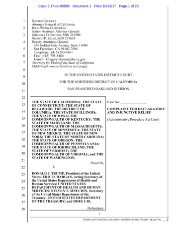
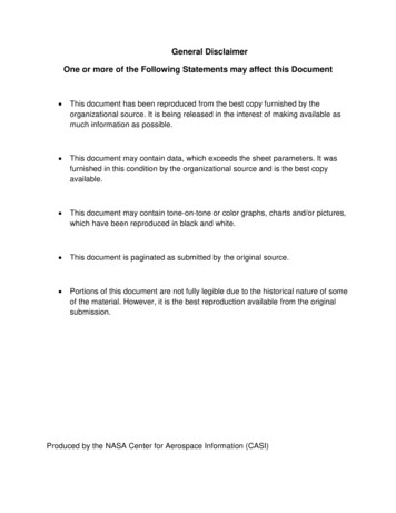
3.4.2 Cells Produced by Process SequenceThis process has been used in fabricating a large numberof cells. An efficiency distribution of float zone Si cells and webcells are shown in Figs. 1 and 2. Figure 1 which shows the float zoneSi distribution which have an average of 14.5% with a maximum efficiencyof 15.5%. These data indicate that the described process is capable ofproducing high efficiency cells. Figure 2, which shows the efficiencydistribution for the web silicon cells, reveals an average efficiency ofabout 13.5%. However, the maximum efficiency is also 15.5% which indicatesthat dendritic web silicon is capable of cells as efficient as thoseprepared from float zone silicon.3.4.3 SAMICS Cost AnalysisThe cost factors of the various sub-processes have beenanalyzed see Sec. 3.4.4 and transferred to Format A's. The total costof the process has been determined using Release III of the SAMICS program.This calculation was made under the following assumptions:25 MW/;r production.5000 cm 2 /min web input; 345 days/yr.Operation with 3 shifts.Web is 5 cm wide.Process produces 12% panels.85% yield of cells.95% yield of panels.With these inputs, a selling price of .75/watt peak wasobtained (1980 ).A breakdown of the contribution of the various sub-processesto this selling price is shown in Table 6.I150
Curve 717997-AEFFICIENCY DISTRIBUTION OF DENDRITIC WEBSOLAR CELLSSPUTTERED AND SILT( SCREENED AL BSF( 12 DI F FERENT WEB CRYSTALS)0. 350. 30UC0. 25LLJC30. 20cV)0. 15VO00. 10ULI.L0. 0501112131415Cell Efficiency( AM-1; A R Coated)16Fig. 1 Efficiency Distribution of Float Zone Silicon Solar CellsSputtered and Silk Screened AL BSF
Corve 717998-PEFFICIENCY DISTRIBUTION OF FLOAT ZONESILICON SOLAR CELLSSPUTTERED AND SILK SCREENED AL BSF0. 350. 30a,0. 25W50. 20crc.jw0. 15U0oA 10LLA-0. 05012131415Cell Efficiency (M-1-1; AR Coated)ti16Efficiency D istribution of Drndriticweb Solar CellsS p"ttered and Silk ScreenedAL GSF(12 different web crystals)17
a,XcN X r0 G1L 01(.7 Av0LNCr0 G1 CoCoaY Y. C) Ln NV'tn.-ix4.—V . Fj - V G1C roC r10Qx.egaJNea - uCCO 21- WNO,o10JQn irpUOUro ZNNS-ri L.ro . zUC]UQIO O co00Ln 47 N "'a'oroWNCLU(J4 pu4JcLd W OuNtJ CcOCLG1VOTOGL1CNN.ry IJ NCL CLG1C Veo (nL .-r0 --CL GJG/ UviLJNcoY OqJJQY01YO 00 YM OM r .---CTcliO OO MLUOGJ1ct 1dr0Q1a H WJmNmNmWULnn iQ Sia1 a1.-UUjVi N4.joQJr0 J4-jLn 1--J r0n i.N3 L7J eaO'WU O L-)}NNNWUOQ 'G.ri.JGJnVNr0 rLnd rr G1C G/C u--0YChUDO U-3OY YO O0cO u O ra,CDOU 4J\ uNV1 l IDtiaJaJV1("AnAfu Jn2irr0 .- oUOUNN U-)Nutr9O rr0 .JaJN }t cnV1ro aJrp rp3 t7f3CO\srO N0L U'L1 al .av( "fN(sl18XOH a Q QU YQ WYY f r0 JQEEni Oa UpU.rj
3.4.4 Costs Used in Format A'sThe Format A's require among other inputs estimation ofthe costs of commodities and capital equipment. To obtain these factors,we requested budgetary estimates from a number of vendors for equipmentsufficiently large for a 25 MW/yr production line. In addition, costbreaks obtainable on larger volume purchases of commodities not listedin the SAMICS Cost Accounting Catalog have been obtained.4. CONCLUSIONSOperational bask surface fields have been produced usingaluminum p layers. Several tests have shown that some of the problemsin achieving an even higher V may be due to the Al IIS formation processocdegrading the front junction.The , crrolab Process Specification for silk screened Al backsurface fields has been tested. The Al BSF cells produced in this wayare essentially equal to those produced using sputtered Al layers.T:.c Motorola Process Specification for total plated cnntpctshas been tested.The specification required considerab;e modification due tothe attack on the antireflection coating by the acidic rinses. Withthese modifications, cells were produced and tested. T
silk screening the silicon between the dendrities involves complicated equipment. The deposited aluminum is alloyed into the silicon by a short heating cycle of one minute at 850 C. Open circuit voltage enhancement of up to 50 mV is noted after the back surface field preparation with maximum Voc's o