Transcription
General Informationfor Installing an Automatic Pool Cover (Save-T 3 or Autosave Spa Cover)This is a general guide on factors to consider for the installationWARNINGof a Save-T 3 automatic coversystem or Autosave spa cover.11ptDetailed installation instructions are available.WARNING12ptWARNING14 ptWARNING21ptFOR YOUR SAFETY—This product must be installed and serviced by a contractor who is licensed and qualified inpool equipment by the jurisdiction in which the product will be installed where such state or local requirements exists.In the event no such state or local requirement exists, the installer or maintainer must be a professional with sufficientexperience in pool equipment installation and maintenance so that all of the instructions in this manual can be followed24ptexactly. Before installing this product, read and follow all warning notices and instructions that accompany this product.Failure to follow warning notices and instructions may result in property damage, personal injury, or loss of life.Improper installation and/or operation will void the warranty.WARNING27ptWARNINGCover-Pools Incorporated66 East 3335 SouthSalt Lake City, UT NINGCover-Pools Incorporated is a wholly owned subsidiary of Zodiac Pool37Systems, Inc.ZODIAC is a registered trademark of Zodiac International, S.A.S.U., used under license.All other trademarks used herein are the property of their respective owners. 2015 Cover-Pools Incorporated800024 Rel-0024
NOTES2All diagrams are for general information. Consult installation instructions for details.
Table of ContentsTRACK OPTIONS. 4EXCAVATION AND PLUMBING. 6Recessed Mechanism—Underside Track or Track Channel. 6Recessed Mechanism—Universal, SnapTop , or Flush Track. 7ELECTRICAL. 8Keyed Motor Control (Standard Equipment). 8Hydraulic Power System. 8Auto-Shutoff with Amp Limiter and Accessory Board. 9Auto-Shutoff with Amp Limiter/Accessory Board/Wireless . 9MECHANISM HOUSING. 10Recessed Concrete, Wood, or UPB Box—Underside Track. 10Recessed Concrete, Wood, or UPB Box—AutosaveOPTION 1: Conduit comes from back of box.11Recessed Concrete, Wood, or UPB Box—AutosaveOPTION 2: Conduit comes from side of box. 12Recessed Concrete, Wood, or UPB Box—Universal or SnapTop Track. 13Recessed Wood Box Construction. 13Deck-Mounted Bench Construction. 13COPING AND DECK. 14Gunite Layout—Underside track. 14Coping or Deck Requirements—Underside track. 14Coping or Deck Requirements—Underside track (cont.). 15Tile Beam—Underside track. 15RECESSED BOX COVER. 16Brackets. 16Vanishing Lid System. 16Bezel lids. 16SPECIFICATIONS. 17COVER SIZING AND PRICING. 18Cost Considerations. 193All diagrams are for general information. Consult installation instructions for details.
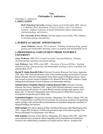
1TRACK OPTIONSBased on the pool design, choose the appropriate track style and any options.ThesizeTrack Channel can be set in a recessed notch below stoneactualor coping level. A lightmortar or grout layer can be applied underUndersideTrackDeck Materialthe stone surface andusedtoin behindchannel if necessary. Mountedfillunderdeck copingDeck Straps For porous coping, brick,flagstone, and materialsless than 2" thick Mounted every 2' of track For deck-on-deck pools Anodized aluminumRECESSED MOUNTINGFOR STONEOR COPING Easier installationandreplacement of ropeForm DTrack Channel For concrete andfiberglass pools Raised-wall applications Track channel allows forcustom cantilever profiles Foam or wood forms canbe incorporated for deckprofiles4"Reusable Coping Form For concrete, fiberglassand vinyl-liner pools Eliminates the need for1-1/4" foam or wood forms Extruded aluminum3½"2-1/2"Form BTrack ChannelInverted Mount For any deck surface, suchas flagstone, slate or tile,that does not meet basicundertrack mountingconditions (surfaces lessthan 2" thick or softermaterials)41/4"4"11/4"Form A15/8"Vinyl-Liner Pool CopingUndertrack System For vinyl-liner pools 90 , 45 , 6" and 24"corners available Tracks locked in placeby shims Standard or bullnosecoping options12¾"4½"StandardVinyl-Liner PoolTrack Channel Track channel allows forcustom cantilever profiles Foam or wood forms canbe incorporated fordeck profiles Can be used withCover-Pools ReusableCoping FormBullnoseAll diagrams are for general information. Consult installation instructions for details.2"
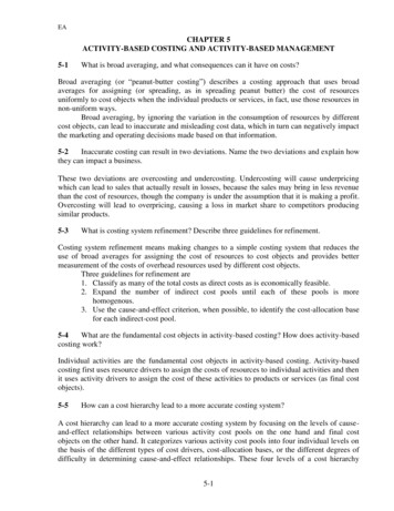
Universal Deck-MountedTrack For existing decks Low profile Installed on surface ofthe deck Anodized aluminum11/16"2-13/16"11/16"2-13/16"SnapTop Track For existing decks Low profile Installed on the deck surface Anodized aluminum Uses gliders or wheels Screws are concealed Standard Universal trackalso available Smaller Slim trackavailable for Step-Saver systemsUniversal track for spasand Step-SaverFlush Track - NEW For new or existing pools Installed flush with deck Vinyl-liner, fiberglass orconcrete pools Anodized aluminum1-1/2"Recommended for Indoor use only3-1/2" – 4"Special Construction ApplicationsDeck-on-Deck PoolsCreate a rectangular framearound the free-form pool foran undertrack installation withtrack channel.Vanishing-Edge PoolsCreate a 45 or 90 vanishing edge45 90 track channel ordeck strapsExtreme CantileverPerimeter OverflowCreate a freeform pool by extending the cantilever up to 24"beyond the channel or track.Create a pool for which water height appears even withthe deck. A narrow channel collects the overflow waterand allows for the glider arms.600198 ILLUS VAN EDGE 45 DEG COVER OPENING DETAIL - DWG1track channel ordeck strapsAll exposed aluminum extrusions can be painted to matchdeck color.2All diagrams are for general information. Consult installation instructions for details.
2EXCAVATION AND PLUMBINGConsider any special requirements for excavation and plumbing.Recessed Mechanism—Underside Track or Track Channel1. The tracks (and rectangular pools) must be a true rectangle. The tracks must beperpendicular to the unit mechanism and recessed housing (90 ).2. Over-dig the recessed cover box end of the pool 18" beyond the forms.Do not install plumbing within 14" of the deck in the housing area.3. The motor can be on either end of the cover box.4. Do not locate skimmers in the lowered pool wall.5. All corners must be square (no radius) on the finished tile line or the coping.6. Place 3" drain in floor or wall of recessed housing.ABPool must be square:AB CDAD CBno radius cornersat pool wall or copingmotor sideopposite sideTrack squared to boxor mechanismGE 6'GF 8'FE 10'EDClowered pool wallmotor side36"excavationfrom waterlineFshaded area excavationG18"16"excavationfrom waterline3All diagrams are for general information. Consult installation instructions for details.
Recessed Mechanism—Universal, SnapTop , or Flush TrackThe requirements of a recessed mechanism with a deck-mounted track are the same as the undertrack on the previouspage. Universal track may be mounted at the pool edge. Flush track must be set back 6" from the pool edge.AB2' beyond poolTRACK DIAGONALS: AD BCTracks must be square:AB CDAD CBTRACK LENGTH: AC BDDo notlocate trackon top of askimmer lid.TRACK SPACE: AB CDTrack squared to boxor mechanismGE 6'GF 8'FE 10'EC1' minimum setbacknon-motor side18"Fmotor sideDG36"16"shaded area excavation4All diagrams are for general information. Consult installation instructions for details.
3ELECTRICALChoose electric or hydraulic power and controlling devices.WARNING! These are minimum recommendations only. All local and federal codes of standard safe practicesmust be followed. Refer to the prewiring instructions for detailed instructions and additional mounting options.Electric Motor w/ Keyswitch (Standard Equipment)¾ hp Motor with Slip ClutchAll switches must bemounted in full view ofthe cover operation.Key Switch 120VConduit to 120 VAC 15AMP dedicated G.F.C.I.(Hot, Neutral, Ground)Pool14 AWG under 50ft12 AWG over 50ftCover Housing14 AWG under 50ft12 AWG over 50ftDedicatedGFCIConduit with three differentcolored wires and one ground.(Neutral, Dir 1, Dir 2, Ground)MOTOR36" of waterproof flex conduit with 1/2"NPT watertight connector 14 AWG Min.Wire extended 8" past conduit end.electric motorWARNING! These are minimum recommendations only.All localand federalPowercodes ofstandard safe practices must be followed.HydraulicSystemAll switches/control pads mustbe mounted in full view of thecover operation.(Optional)Option 1:Key Switch KOSAPOOLConduit With (3)12 AWG (min)Identified Wiresplus one groundGreenLEDORRedLEDOption 2:CoverLinkWired ControlConduit with (4)18 AWG (min)Identified Wiresfor CoverLinkWired ControlCOVER HOUSINGHYDRAULIC MOTOR ENDLARGE SWEEPING BENDSDedicatedGFCIConduit to HYD pump J-box with2 identified wires and 1 ground14 AWG under 50ft12 AWG over 50ftHYD PUMP UNITmotortwo 1/2" hosesover 80'Hydraulic motors must bemounted above ground level.3" conduitCONDUIT FOR HYDRAULIC HOSEWITH SWEEPING BENDS050275 or 050276hydraulicHydraulic Pump Unit3" poly or PVC pipe fromhousing to power unit.NO SHARP BENDS!5All diagrams are for general information. Consult installation instructions for details.
Auto-Shutoff with Optional Accessory Board/AquaLink All switches/control pads mustbe mounted in full view of thecover operation.¾ hp Motor or Hydraulic MotorOption 1: Auto-shutoff mounted outside housing.GreenLEDOption 1:Key Switch 5vRedLEDConduit with (3)18 AWG IdentifiedWires for LowVoltage Key SwitchConduit with (4) 18 AWG (min)Identified Wires for CoverLinkWired ControlORPOOL#8 Bonding WireBoth EndsASInstall auto-shutoff away from cover housingin or by equipment room or equipment pad14 AWG under 50ft12 AWG over 50ft DedicatedGFCIMOTORJ-box36" of Waterproof Flex Conduitwith 1/2" NPT Water TightConnector, Extend (4) 14 AWGWires 8" Past Conduit EndConduit for Main Power with (3)14 AWG Identified Wires(Hot, Neutral, Ground)Auto-Shutoff with Accessory Board/ AquaLink and Wireless(Optional) -- ¾ hp Motor or Hydraulic MotorGreenLEDRedLEDPTIONCoverLink WirelessControl PadCLEAR LINE OFRECEPOOLCOVER HOUSING#8 Bonding Wire(Both Sides)Hydraulic motorsmust be mountedabove ground level.ACC Optional Accessory Board or AquaLinkConduit with (4) 18 AWG WiresConduit with (4)14 AWG WiresFor Power and (3)18 Awg for SensorsCOVER HOUSING050275 or 050276Hydraulic1-1/2Hydraulic PumpUnit hp motorOption 2:CoverLink Wired ControlACCReceiverelectric 3/4 hp motorAll control pads must be mounted infull view of the cover operation. Installthe accessory board in or by theequipment room or equipment pad,away from the cover housing.Hydraulic motors050275 ormust050276be mountedHydraulicabovePump Unitground level.Optional Accessory Board or AquaLinkConduit with (4) 18 AWG WiresInstall acc board away from cover housingin or by equipment room or equipment padASDedicatedGFCI14 AWG under 50ftAuto-shutoff12 AWG over 50ftAntennaConduit for Main Power with (3) 14 AWGIdentified Wires (Hot, Neutral, Ground)36" of Waterproof Flex Conduit with 1/2"NPT Watertight Connector for 14 AwgWire Extended 8" Past Conduit Endelectric 3/4 hp motor6All diagrams are for general information. Consult installation instructions for details.
4MECHANISM HOUSINGChoose a recessed mechanism (concrete or wood box) or deck-mounted mechanism. Systemsinclude a lid assembly, bench frame assembly or fiberglass ends.Recessed Concrete, Wood, or UPB Box—Underside Trackconduit must be on themotor endPOOLconduit should notprotrude morethan 4" into boxconduit 6" maxfrom topof boxBpool beam wallMbond wireT[ODdrain centerline 4"max from end wallbond wireW3" drain - floor or wallcan be on either endwall cut away for clarityConsult a certified electrician and the pre-wiring diagrams for conduit and bonding requirements.Underside TrackBox Dimensions for Save-T 3MOTORMOPPOSITEOBEAMBTHROATTDEPTHDWIDTHWPools under55 ft. long x 24 ft. wide32"10"8-12"2" min tofinished beam12-1/2"min12-1/2"minUPB BOX Pools up to55 ft. long32"10"8-12"2" min tofinished beam13"13"Pools over55 ft. long x 24 ft. wide32"10"8-12"2" min tofinished beam14½"14½"Pools over 65 ft. long or 25 ft. wide and vanishing-edge pools — Call Cover-Pools 1-800-447-2838lidBox Side View—Underside Trackminimum 2" clearancefor tracks7Optional coping or condrete build up.All diagrams are for general information. Consult installation instructions for details.
Recessed Concrete, Wood, or UPB Box—AutosaveOPTION 1: Conduit comes from back of box.POOLBpool beam wallMTODdrain centerline 4"max from end wallWConduit comes fromcenter of the housing3" drain - floor or wallcan be on either endrecessed box wallcut away for claritybond wire to bonding grid (route so that cover will not rub or catch or interfere with mechanism)Consult a certified electrician and the pre-wiring diagrams for conduit and bonding requirements.8-1/2"Underside TrackBox Dimensions For Autosave Up to 13' or200 square feetMotorMOppositeOBeamBMotor Behind9" min9" min14-1/2" minw/ Auto-ShutoffMotor Beloww/ Auto-ShutoffMTR ConduitThroatTDepthDWidthW10" min1" to Finished Beam9"min12-1/2" min9" min10" min1" to Finished Beam9"min12-1/2" min12-1/2" min9" min10" min1" to Finished Beam9"min12-1/2" min12-1/2" min9" min10" min1" to Finished Beam9"min14-1/2" min12"Side View8-1/2"MTR Conduit12"12"MTRConduit8-1/2"Motor BehindMotor BelowNote: To avoid interference, run the conduit from the center of the box using flex conduit with 1/2" water tight connector.8All diagrams are for general information. Consult installation instructions for details.
Recessed Concrete, Wood, or UPB Box—AutosaveOPTION 2: Conduit comes from side of box.conduit must be as close torear wall as possible formechanism clearance.conduit should notprotrude morethan 4" into boxPOOLBpool beam wallMODT3" drain can be on either endWrecessed box wallcut away for claritydrain centerline 4"max from end wallbond wire to bonding grid (route so that cover will not rub or catch or interfere with mechanism)Consult a certified electrician and the pre-wiring diagrams for conduit and bonding requirements.MTR8-1/2"Underside TrackBox Dimensions For Autosave Up to 13' or200 square feetMotorMMotor Behind9" min9" min10" min14-1/2" min9" min12-1/2" min12-1/2" minw/ Auto-ShutoffMotor Beloww/ Auto-ShutoffOppositeOBeamBDepthDWidthW1" to Finished Beam9"min12-1/2" min10" min1" to Finished Beam9"min12-1/2" min9" min10" min1" to Finished Beam9"min12-1/2" min9" min10" min1" to Finished Beam9"min14-1/2" min12"ThroatTConduitSide View8-1/2"MTR12"MTR12"ConduitMotor BehindConduit8-1/2"Motor Below9All diagrams are for general information. Consult installation instructions for details.12"
Recessed Concrete, Wood, or UPB Box—Universal or SnapTop TrackPOOLconduit must be on themotor endconduit should notprotrude morethan 4" into boxConsult a certifiedelectrician and thebond wirepre-wiring diagrams forconduit and bondingrequirements.Bpool beam wallconduit 6" maxfrom topof boxODMdrain centerline 4"max from end wall3" drain - floor or wallcan be on either endDeck Mount TrackBox Dimensions for Save-T 3bond wireWwall cut away for s under 55 ft. long x 24 ft. wide32"10"8-12"2" min to finished beam12½" min12½" minUPB BOX Pools up to 55 ft. long32"10"8-12"2" min to finished beam13"13"Pools over 55 ft. long x 24 ft. wide32"10"8-12"2" min to finished beam14½"14½"Pools over 65 ft. long or 25 ft. wide and vanishing-edge pools — Call Cover-Pools 1-800-447-2838Recessed Wood Box Constructionside view36"Requirements:The material used to construct the box should be:2" x 12" pressure-treated lumber or pper trim:2" x 4" pressure-treated lumber or redwoodtopviewsideview14½"14½"Deck-Mounted Bench ConstructionEverlast Bench KitModular bench kit uses adjustableheight brackets and polymer panelsto create a low-maintenance benchsystem.Bench FrameThree-piece adjustable steelbrackets provide a maximum heightof 20" by 24" wide. Surface materialis not included.16¼"to17½"Also available withstainless-steel base.20"Available in 4 colorsDeck-Mounted Fiberglass Endsroller tubeFiberglass ends are an economical andpractical solution to cover the deck-mountedmechanism. Available in white.10All diagrams are for general information. Consult installation instructions for details.
5COPING AND DECKConsider the requirements for coping and deck installation.Gunite Layout—Underside trackformformbrace16 d nails2" offsetin steelcoverboxtop of side wallformside wallside wall2½" lower thanside wall2½" lowerbondbeaminterior wallAt the recessed box end, the pool wall (bond beam)must be shot 2½" (2" finished with tile) lower thanthe side walls.The top inside pool corners (above the waterline)must be square, not radius.Any interior wall, such as for spas, also must be gunited2½" (2" finished with tile) lower than the side walls.Coping or Deck Requirements—Underside track3" cantileverno radius corners2" cantilever sidewalls All corners of the coping must be square Minimum 2" cantilever from tileon side walls Minimum 3" cantilever from tileon end wall opposite the mechanismlowered pool wallmotor11All diagrams are for general information. Consult installation instructions for details.
Coping or Deck Requirements—Underside track (cont.)bull noseOpening for the track must be 2½" at box(2" finished with tile), sloping to 3" inside pooldeckingDECKING2" min2" min.POOL WALL2" min2" minimumfromtilefrom tile2" cantileverbox minimum12 ½" wide x 12 ½" deepPool wallNOTE: The track must be mounted on the flatbottom of the coping. The coping measurementis NOT the track space. Coping must not extendmore than ½" past the edge of the track.TRACK SPACETile Beam—Underside trackThe lowered pool wall is finished with a tile surface.Bull noseFor the lowered wall edge, use aDeckingrounded tile on the front and back edges to minimize scraping on the cover.DECKTrack Space2" min.Opening 2" finished withtile or other material2" min.POOL1/4" round edge1/4"edgeroundedge1/4" roundif exposed12All diagrams are for general information. Consult installation instructions for details.
6RECESSEDBOXCOVER600104 ILLUSVANISHINGLID CORNER BRACKET - DWG1.aiChoose lid and brackets to cover recessed box.Brackets24" max.18" max.tray or stonetray or stoneStandard Aluminum LidTilted Bracketfor Universal, Snaptop ,and Flush Track Stepped or tilted anodizedaluminum lid availablewith 4" or 6" hingeStandard Aluminum LidFlat Bracketfor Underside Track Standard anodizedaluminum lid availablewith 4" or 6" hingeVanishing Lid Adjustable 12"Stainless-Steel Bracket For any tray lessthan 18" Extensions 14½" & 17½"availableVanishing Lid Adjustable 18"Stainless-Steel Bracket Maximum bracketspacing is two feet For trays 18-24" wide Extensions 20½" & 23½"availableBezel lids1½3 /8"Flush Mount Lid for vinylliner pools with UPB BoxFlat Bezel LidTilted Bezel Lid1½Stepped Bezel LidAvailable in 16" widthwith 16" or 18" endsAvailable in 16" or 18" widthVanishing Lid SystemNOTE:Walk-on Vanishing Lid systems require a concrete housing,or, if using a wood housing, a concrete wall must be pouredbehind the box for anchoring brackets.Walk-On Vanishing LidThis design offers an adjustable tray support system for any type ofdeck material. Stainless-steel or aluminum trays and stainless-steelbrackets provide the support base for a strong walk-on lid that canblend with the surrounding deck.M6"inNote: The deck thickness must beincreased for extended trays if the leadingedge is going to fit under the tray. ContactCover-Pools for more information.The maximum width of any tray is 24".The maximum length of tray is 24".13All diagrams are for general information. Consult installation instructions for details.
7SPECIFICATIONSReview system details for Save-T covers.Quad-core Fabric Material: PVC vinyl, laminated over a reinforcedpolyester mesh for strength and tear resistance Rigorously Tested: The exclusive formula is theproduct of 50 years of testing and experience Designed for the Pool Environment: UV, mildew,and pool-chemical resistant with superiordimensional stability Weight: 18 oz. per square yard Thickness: 28 mil laminated vinyl Strength: Exceeds the ASTM F1346-91 minimumstandard of 485 lbs. per 4' radius Construction: Fabric is attached to webbing andlow-stretch rope (70,000 cyclic loading fatigue life)with double-sewn Dabond bonded polyester thread fordurability 11 standard colors: dusky blue, royal blue, light blue,aqua, forest green, beige, tan, brown, gray, slate gray,and black Additional special-order colors available 7- year limited prorated standard warranty Sewn webbing in 9 optional colors Optional Ultimate heat sealed webbing in 6 colors Optional Ultimate rope (100,000 cyclic loadingfatigue life) or Stainless steel cableTrack Styles 7-year limited warranty on all aluminum extrusions All aluminum extrusions are 100% anodized Underside , SnapTop , Universal, Slim , or Flushtrack Safety-Lock track channel Top-mounted track channel for concrete andfiberglass pools Inverted track channel for concrete ordeck-on-deck applications Track channel system for vinyl pools Coping channel for vinyl pools V-Pak kit for vinyl pools (includes system, fabric,channel, box, and lid) Reusable coping forms (3 Profiles) 45-degree vanishing-edge pools 90-degree vanishing-edge pools NEW Corr-Resist non-metallic Track ChannelMechanism Housing Standard 12" aluminum lid with either 4" or 6" hinge Bezel lids, 16" and 18" wide Vanishing Lid trays, 12"–24" wide with stainless-steeltrays and stainless-steel adjustable brackets Fiberglass deck-mounted mechanism end housings Ultimate Polymer recessed box Everlast modular bench kit (available in 4 colors) Bench frame assemblyPower and Controls 3-year limited warranty on all electrical 3/4 hp waterproof electric motorOptional Ultimate High-Torque Motor 1 ½ hp/2000 PSI hydraulic systemSafety lockout key controlCoverLink touchpad control (wired or wireless)Low-voltage auto-shutoff with key switchWater-feature shutoffJandy iAquaLink InterfaceSafety Exceeds ASTM F1346-91 requirementsFull UL listingBonding included with all automatic systemsAutomatic water-removal cover pump included NOTE:Some cover manufacturers treat cover pumps andbonding as options for their systems. A solid safetycover without a pump is NOT approved to ASTMF1346-91 safety standards. The installation of anautomatic cover system without bonding is not aUL-listed product.Other Options Painting—all extrusions can be painted to match mostdeck surfaces or fabric colorsMechanism Exclusive Corr-Resist end hubs with stainless steel,designed for salt water systems Marine-grade anodized aluminum frame and bracket Limited lifetime warranty Exclusive positive-shift system Exclusive Corr-Resist rope reel with stainless steel sideplates designed for quiet operation Standard electric system comes with either the slipclutch or auto-shutoffAll diagrams are for general information. Consult installation instructions for details.14
8COVER SIZING AND PRICINGDetermine pricing according to the cover specifications.Pricing based on motor mechanism being installed one foot from pool edge, motor position on left or right.UndertrackDeck-Mounted Track2'Track SpacePool LengthTrack SpaceTrack SpacePool Length1'Mechanism1'MechanismTRACK SPACE x POOL LENGTH COVER SQUARE-FOOT PRICINGTrack widths over 25' or lengths over 65' require factory approval (maximum track space is 36').15All diagrams are for general information. Consult installation instructions for details.
Cost ConsiderationsExcavation/PlumbingTrackqq Housing excavationUnderside track or Universal track standardqq 3" drain for housing drain— drain to airor drain to pit(2 or 3 sided)qq 3" conduit for hydraulic-unit housingqq Flush trackqq SnapTop trackElectricalqq 1/2" Conduit for mechanism powerqq Electric run to key switchqq 15-amp GFCI dedicated circuit for mechanism atpanel (20 AMP for hydraulic)qq Electric runs over 50' require heavy-gauge wireqq Electrical run for accessory boardqq 1/2" Conduit (for low voltage wires) required withAuto-shutoff/CoverLink wired controlsqq Vinyl-liner pool coping 90 , 45 , 6" radius or 24"radiusqq Track channel for vinyl-liner poolsqq Vanishing edge 45 or 90 qq Painted track extrusionsHousingAluminum lid, bench frame or fiberglass ends standardqq Painted lid extrusionsqq Aluminum Lids: Standard, Bezel lids, or Flush MountConcreteqq Concrete, gunite or shotcrete box, minimum 6" thick,3500 PSI, (no rebound)qq Additional deck around housing/mechanismqq Tile on lower beam, beam cover or otherqq Walk-on Vanishing Lid traysqq Bench for deck-mounted mechanismPower/Controls110 V motor and hard-wired 3-wire key standardqq Auto-shutoff control with amp limitCover/Mechanismqq Unit price based on track space x pool lengthincluding steps, plus optionsqq Track space 25' 6" or more may require a largermain mechanism tube and larger leading edgefor fabricqq Track channel for concrete or fiberglass poolsqq Wireless CoverLink digital touchpad controlqq Wired CoverLink digital touchpad controlqq Water-feature shutoff/accessory boardqq Hydraulic pump with hydraulic hosesqq Jandy iAquaLink interface & control16All diagrams are for general information. Consult installation instructions for details.
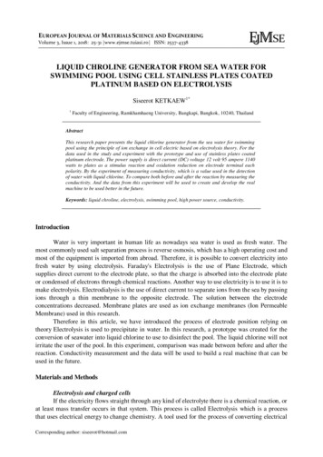
QUAD-CORE 18ozLOW-STRETCH ROPE3/4 hp WATERPROOF MOTOREXCLUSIVE!HYBRID ROPE REELwith CORR-RESIST componentsKEY SWITCH····compact potted waterproof designadjustable amp limiter overloadsafety circuitLED indicator and diagnostic lightsoptional water-feature controlboard (can control 12- and 24-voltmotorized valves orpump motors up to 30amps)AUTO-SHUTOFFWITH AMP LIMITER· cover status controls poolfeatures· view if cover is open/closed· reduce the filter pump time· adjust AquaPure output· turn off water features, lights,and booster pumpcleaners when thepool is covered.· connect to an iPhonewith the iAuquaLink AquaLink interface Board· 10-number wireless orwired touch pad· wireless systems usesecure FM-radiotechnology with signallock· fits in a single gang box· uses AA batteriesCOVERLINK CONTROL· 3-wire key switch forsimple wiring· mounts in standardswitch box· NEW brushed stainlesssteel faceplate(high-voltage only)EXCLUSIVE!HYBRID END HUB withCORR-RESIST componentsWEBBING STOP BLOCKSAVE-T 3 “BIG RED”NEW GLIDER STOPROLLER TUBE BRAKE· stainless-steelbrake adjuster· easy to adjust· keeps cover taughtEXCLUSIVE!MARINE-GRADEANODIZED ROLLER DRUM· strong 17 gauge thickaluminum tube· 6" & 8" diameters available· anodized aluminumprotects against corrosionand oxidation· stainless steel andCorr-Resist components· designed for mineral sanitizingsystems· minimizes salt corrosion· can be retrofitted to previousmodels· 70,000 cycle loading fatigue life· prevents glider from· simple installation to setFABRIC COLORS· attached with double-sewn,running past the trackcover travel length· dusky blueDabond bonded polyester· ensures cover stops in· clamp design allows· royal bluethread.correct positioneasy adjustment· light blue· attaches to track· aquaULTIMATE ROPE· forest green· 100,000 cycle loading fatigue life· beige· tanSTAINLESSSTEELCABLE· brown· superior durability in a poolPOSITIVE SHIFT SYSTEM· grayenvironment· all stainless-steel shaft and· slate gray· does not stretch or shrink,shifting-dog components· blackreducing realignment service· no shear pins or bolts· Optional colored webbing calls· 3/8" solid stainless-steelor Heat Sealed Webbingdrive dowel······3/4 hp, 41 rpm,1600 in-lbs of torquecapacitor-start, capacitor-runO-ring sealed and pottedwire-entry pointsstainless-steel gears withsealed permanent greaseUL ListedOptional Ultimate Hi
of a Save-T 3 automatic cover system or Autosave spa cover. Detailed installation instructions are available. General Information for Installing an Automatic Pool Cover (Save-T 3 or Autosave Spa Cover) Cover-Pools Incorporated 66 East 3335 South Salt Lake City, UT 84115 800.447.2838 801.484.2724 www.coverpools.com 2015 Cover-Pools .