Transcription
HandPunch3000/4000ManualATR Systems, Inc.Time & Labor Management SolutionsTel: 215.443.8720Fax: P/N: 70100-6003 Version 3.0
This equipment has been tested and found to comply with the limits for a Class B digital device,pursuant to part 15 of the FCC Rules. These limits are designed to provide reasonable protectionagainst harmful interference when the equipment is operated in a commercial environment. Thisequipment generates, uses, and can radiate radio frequency energy, and, if not installed and used inaccordance with the Installation Manual, may cause harmful interference to radio communications.Operation of this equipment in a residential area is likely to cause harmful interference, in whichcase the user will be required to correct the interference at the user’s own expense.This Class A digital apparatus meets all requirements of the Canadian Interference-CausingEquipment Regulations.Cet appareil numerique de la classe A respecte toutes les exigences du Reglemente sure le materielbrouilleur du Canada. 1998 through 2003 Recognition Systems, Inc. – ALL RIGHTS RESERVEDDocument Part Number: 70100-6003 – Revision 3 – July, 2003HandPunch is a trademark of Recognition Systems, Inc.The trademarks used in this Manual are the property of the trademark holders. The use of thesetrademarks in this Manual should not be regarded as infringing upon or affecting the validity of anyof these trademarks.Recognition Systems, Inc. reserves the right to change, without notice, product offerings orspecifications.No part of this publication may be reproduced in any form without the express written permissionfrom Recognition Systems, Inc.
Table of ContentsIntroduction 3Biometrics 4Principle of Operation 4Specifications 7Planning an Installation 11Site Preparation 11HandPunch Placement 11Wiring 12Power Input 12Battery Backup 12Earth Ground and Shielding 13Communications 18External Devices 20Mechanical Installation 23Wall Plate Installation 23Mounting the Wall Plate 24Networking and Communications 27Stand-alone HandReader 27Master or Remote HandReader in a HandReader Network 27Remote HandReader in a HandReader Network Connected to a Host PC 27Remote HandReader Connected to a Host PC via Optional Modem 28Remote HandReader Connected to a Host PC via Optional Ethernet 29Printer 29Wiring Connections 31Erasing the Memory 43Closing the HandPunch 45Enter Command Menu 47If No One is Enrolled in the HandPunch 47If Users are Enrolled in the HandPunch 47Navigating Command Menus 49Programming the HandPunch 51Service Menu 54Setup Menu 56Management Menu 60Enrollment Menu 63Special Menu 67HandPunch Maintenance 69Appendix A - Installation Tips 71
Appendix B - Differences in Board Layout 73Appendix C Old Installation Guide 77Appendix D - Troubleshooting 95Glossary 97Limited Warranty 99
HandPunch 3000/4000 ManualIntroductionThe HandPunch 3000/4000 is part of Recognition Systems’ 3rd generation lineof biometric hand geometry Time and Attendance Terminals1. The HandPunchrecords and stores a three-dimensional shape of the human hand forcomparison and identity verification. Upon verification, the HandPunch recordsthe time, date, user ID number, and collected time and attendance data forcollection by a host computer. The HandPunch can produce an output that canunlock a door and it can communicate with a host computer. The HandPunchalso has auxiliary inputs and outputs that can be used to control other systemssuch as bells and alarms.The HandPunch provides proof-positive employee verification combined withthe sophisticated operating features one expects in a modern Time andAttendance Terminal. Because of this unique combination of capabilities, theHandPunch provides the most accurate Time and Attendance data collectionterminal available. The key features of the HandPunch include: Programmable Function Keys- HP-3000 – 2- HP-4000 – 10User Time RestrictionsSupervisor Override at the “Time Clock”- Add Punch- Add Bulk Hours or Dollars- Review PunchesDepartment TransfersExplicit Punch MenuTransaction Buffer- HP-3000 – 5,120 event capacity- HP-4000 – 7,680 event capacityBell SchedulesDoor Control and MonitoringProgrammable Clock and Date Formats and Daylight Savings Switch-overThe HP-4000 also includes: Integrated Bar Code Reader Programmable User Messages Data Validation1. For the sake of using a consistent name throughout the manual, the HandPunch 3000/4000 terminal is referred to as the HandPunch for the remainder of this manual.Page 3
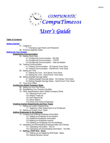
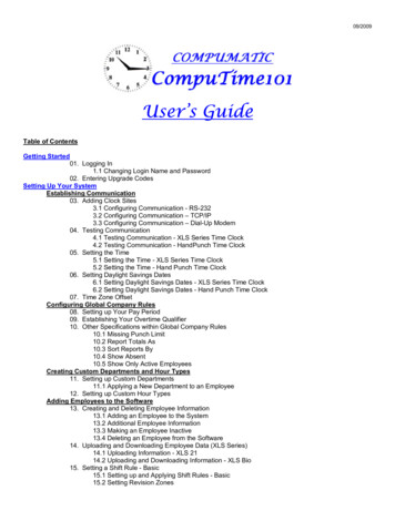
IntroductionBiometricsBiometrics is a term describing the automatic measurement and comparison ofhuman characteristics. While its origins are ancient, the evolution of advancedscanning and microprocessor technology brought biometrics into everyday life.Electronic hand geometry technology first appeared in the 1970s. RecognitionSystems Inc., founded in 1986, built the first mass-produced hand geometryreaders and made biometric technology affordable for the commercial market.Today, Recognition Systems’ products are in use in every imaginable applicationfrom protecting cash vaults to verifying employee attendance in hospitals.Principle ofOperationThe HandPunch uses low-level infrared light, optics, and a CMOS camera tocapture a three-dimensional image of the hand. Using advanced microprocessortechnology, the HandPunch converts the image to an electronic template. Itstores the template in a database along with the user’s ID number.To gain punch, the user enters his or her ID number at the HandPunch’s keypador uses an external card reader. The HandPunch prompts the user to place his orher hand on the HandPunch’s platen1. The HandPunch compares the hand onthe platen with the stored user’s unique template. If the images match, theHandPunch records the transaction for processing.TheHandPunchTerminalThe HandPunch is a time and attendance terminal designed for use with timeand attendance software. Refer to Figures 1-1 on page 5 and 1-2 on page 6 whenreviewing the information in this section.The HandPunch has an integrated keypad for ID entry and reader programming.The HandPunch 3000 has two function keys (F1 and F2 – see Figure 1-1). TheHandPunch 4000 has ten function keys (F1 through F10 – see Figure 1-2). Thesefunction keys can be programmed to collect data or to activate auxiliary outputs.The CLEAR and ENTER keys assist in data entry and programming.1. The Platen is the flat surface at the base of the HandPunch (see Figure 1-1). This iswhere users place their hands for enrollment and verification. It has guide pins to assistpositioning the fingers during use.Page 4
HandPunch 3000/4000 ManualFour different features assist the user with hand placement and read verification.1. A light emitting diode (LED) hand placement display on the HandPunch’s toppanel assists users with hand placement on the platen.2. A liquid crystal display (LCD) shows operational data and programmingmenus.3. “Red light/Green light” verification LEDs quickly inform users if their verification attempts were rejected or accepted.4. An internal beeper provides audible feedback during keypad data entry anduser SLCD DISPLAYRecognitionSystems F1FUNCTIONKEYSPLATEN AND GUIDE PINSFigure 1-1: The HandPunch 3000Page 5
LCD DISPLAYRecognitionSystems rF1F8F5EnterF9F6F10BAR CODECARDREADERFUNCTIONKEYSPLATEN AND GUIDE PINSFigure 1-2: The HandPunch 4000Page 6
HandPunch 3000/4000 ManualSpecificationsTable 1: SpecificationsSize:8.85 inches wide by 11.65 inches high by 8.55 inches deep22.3 cm wide by 29.6 cm high by 21.7 cm deepPower:12 to 24 VDC or 12 to 24 VAC 50-60 Hz, 7 wattsWeight:6 lbs (2.7 kg) – 7 lbs (3.2 kg) with optional backup batteryWiring:2 twisted-pair, shielded, AWG 22 or larger (such as Belden 82732)Temperature:-10 C to 60 C – non-operating/storage (14 F to 140 F)5 C to 40 C – operating (40 F to 110 F)Relative Humidity NonCondensing:5% to 95% – non-operating/storage (non-condensing)20% to 80% – operatingVerification Time:1 second or lessMemory Retention:5 years using a standard internal lithium batteryTransaction Buffer:HP-3000 – 5,120 transactionsHP-4000 – 7,680 transactionsID Number Length:1 to 10 digitsBaud Rate:300 to 28.8 K bpsCommunications:RS-232, RS-422, optional Modem, optional EthernetUser Capacity:HP-3000 – 512 users expandable to 40,xxxHP-4000 – 530 users expandable to 5,xxxMessage Capacity:HP-4000 – 550 expandable to 3520 (not available with the HP-3000)Function KeysHP-3000 – 2 user definable, HP-4000 – 10 user definableCard Reader Input:Proximity, Wiegand, Magnetic Stripe, Bar Code(5 VDC provided by HandPunch unit)Door Controls:Lock output, Request to Exit input, Door Switch input(open collector, 5 VDC present, sinks to ground, 100 mA max)Alarm Monitoring:Tamper, Door ForcedEvent Monitoring:There are a variety of monitoring options including events such as:Invalid ID, Time Zone Violation, ID Refused, Try Again,Power FailureTime Zones:62 total: 2 fixed, 60 programmablePage 7
IntroductionTable 1: SpecificationsTime Schedules:HP-4000 – 3 definable time schedules per userAuxiliary Inputs2 (open collector, 5 VDC present, sinks to ground, 100 mA max)Auxiliary Outputsup to 3 user definable(open collector, 5 VDC present, sinks to ground, 100 mA max)OptionsHandPunch units have the following options available. Backup Battery SupportRev. DModem CommunicationRev. DEthernet CommunicationRev. DSee Technical Note 70200-0012 –See Technical Note 70200-0013 –See Technical Note 70200-0014 –Recommended European Power Supply1:Ault, Inc.7300 Boone Ave. NorthMinneapolis, MN 55428 USAPH: 612-493-1900E-mail: info@ault.comPart number: D48-121000-A040G230 VAC Input, 12 VDC @ 1Amp output (unregulated)Ault style #41 connector (barrel plug)approvedrecyclable1. Not evaluated by UL for UL 294 installations.Page 8
HandPunch 3000/4000 ManualULComplianceThe HP-3000 and HP-4000 meet UL compliance requirements for UL 294Access Control Systems under this condition:1. The HandPunch is configured at the factory with a Wiegand output thatenables the HandPunch to communicate with an access control panel. Theaccess control panel controls the locking and unlocking of the door. Thepanel must reside on the secure side of the facility.Page 9
IntroductionThis page is intentionally blank.Page 10
HandPunch 3000/4000 ManualPlanning an InstallationSitePreparationBefore you begin installation, check the site blueprints, riser diagrams, andspecifications for important information about the HandPunch’s location andother systems that will connect to the HandPunch. Look for any existing wallpreparations and wiring that other contractors may have installed for theHandPunch. A wire routing layout diagram (see Figure 3-2 on page 25) isprovided to assist in planning.HandPunchPlacementThe recommended height for the HandPunch platen is 40 inches (102 cm)from the finished floor. The HandPunch should be out of the path of pedestrianand vehicular traffic, and convenient too, but not behind the door it iscontrolling. Avoid placing the HandPunch where users must cross the swingpath of the door. The HandPunch should be in an area where it is not exposedto excessive airborne dust, direct sunlight, water, or chemicals.40 in. (102 cm.)Figure 2-1: HandPunch Placement RulesNOTEFor the following sections, Recognition Systems does not supply hardwareitems such as door control relays, door locks, switches, relays, communicationsor power wiring.Page 11
Planning an InstallationWiringFour basic circuits typically connect to the HandPunch: Power Input Earth Ground and Shielding Networking and Communications External DevicesThe minimum wire size for these circuits is AWG 22; the maximum wire size isAWG 18. RSI recommends using Belden 82732 or its equivalent when wiring forRS-422 communications.PowerInputThe HandPunch uses an internal switching regulator to obtain internaloperational power. It accepts input voltages from 12 to 24 VDC or 12 to 24 VACat 50 to 60 Hz. The HandPunch comes with a 120 VAC to 13.5 VDC powersupply (Class 2, Model No. P48131000A010G-120 VAC, 60 Hz, 21 W, 13.5 VDCoutput @ 1000mA), if need an optional 220 VDC power supply is also available(this power supply was not evaluated for UL 294).To power the HandPunch with this power supply, a 120 VAC (or 220 VAC asapplicable) duplex outlet must be within 5 feet of the HandPunch. The powersupply has a 6-foot cable to provide a comfortable reach between power outletand HandPunch. The barrel jack at the of the power supply’s cable is connectedto J12 on the HandPunch PCB.BatteryBackupPage 12NOTEJ6 terminal 1 and the center pin of power jack J12 are connected together.J6 terminal 2 and the sleeve of power jack J12 are connected together.NOTENeither terminal 1 or terminal 2 is connected to the HandPunch ground.NOTEDo not connect a HandPunch's power supply to a switched duplex outlet. TheHandPunch must have a constant source of power for proper operation.The HandPunch uses an internal switching regulator to obtain internaloperational power. It accepts input voltages from 12 to 24 VDC or 12 to 24 VACat 50 to 60 Hz. An optional power-fail protection circuit board can be attached tothe main circuit board to provide and control battery backup. The design of theinternal power supply is such that any range of the above input voltages may beused and still provide proper battery charge voltage and battery backupoperation. Switch-over to battery power is automatic and occurs when the inputvoltage falls to approximately 10.5 volts. At that time the internal battery chargeris disabled to save power and uninterrupted operation continues on batterypower.
HandPunch 3000/4000 ManualWhen input power is restored, the HandPunch switches off of battery operationand the battery charger is re-enabled to recharge the battery. Battery chargevoltage is set at approximately 13.65 volts, and battery charge current is limitedto approximately 50 mA. A fully discharged battery requires approximately 12hours of charge to fully recover.Additional options installed and specific configurations within the HandPunchmake it difficult to predict precisely how long battery support will last, but ingeneral two hours of battery operation can be expected. While operating onbattery backup due to loss of main input power, the battery output voltage isconstantly monitored by internal circuitry. If the battery voltage reachesapproximately 9.5 volts the HandPunch automatically shuts down. This is doneto prevent full exhaustion of the battery. A yellow indicator on the top panelilluminates to indicate that the HandPunch is running off of battery power. Thisindicator extinguishes when main input power is restored.Shunt J7 which is located to the left of TS3 see Figure 4-1 on page 27 enables ordisables battery operation on those HandPunchs equipped with optional batterybackup. If a HandPunch does not have the optional battery backup packageinstalled, J7 is not used. On HandPunchs equipped with the battery backupoption, J7 allows service personnel a mechanism for disabling battery backupoperation before removal of main input power. To fully power down aHandPunch equipped with battery backup, remove or reposition shunt J7 so thatthe two pins protruding up from the main logic board are not connected to eachother. This effectively opens the circuit, removing the battery from any internalcircuitry. Main input power can then be removed and the HandPunch will fullyshut down. Once the HandPunch has fully shut down, shunt J7 may bereinstalled. The design of the power supply is such that main input power mustbe reapplied to re-enable the battery protection mechanism. If shunt J7 is notproperly installed, the internal backup battery will not be charged, and in theevent of a main input power loss, the HandPunch will shut down.The HandPunch with the battery backup option uses a 12 volt 800 ma/hoursealed lead acid battery to provide backup battery power. This battery is locatedimmediately inside the rear panel of the HandPunch and plugs into jack J4 onthe keypad control circuit board located in the top of the chassis.EarthGroundandShieldingRecognition Systems recommends that all HandPunchs be grounded with asolid, reliable earth ground connection. This connection establishes a commonground return point used to protect internal semiconductor devices fromElectroStatic Discharge (ESD) and from external signal line transients. It alsoprovides a common signal level reference point between externally networkedHandPunchs. Recognition Systems recommends that the earth ground sourcePage 13
Planning an Installationbe identified by a qualified electrician familiar with electrical codes as well aswiring and grounding techniques.This is an extremely important and often overlooked aspect of hard-wired serialcommunication systems. If the sending and receiving stations do not agree onthe ground reference for the signal voltages, communication errors or a totalinability to communicate may be observed. If the voltages are very different, it iseven possible to damage the units.The subject of grounding can be complicated, and the full circuit of a system,including power supplies and often even the building line power wiring, must beunderstood. It is strongly recommended that a qualified electrician or electricalengineer familiar with this subject be consulted when designing the wiring of anHGU network installation. Always adhere to any applicable electrical codes foryour area. Recognition Systems is not responsible for damage done to units dueto improper wiring.Use any one of the following ground terminals to make the earth groundconnection: 4, 10, or 13. Do NOT use terminal 2 to establish the earth groundconnection; terminal 2 is not directly connected to ground.86754321CARDREADERINPUT14 13 12 11 10 9NOTESWITCHINPUTSOUTPUTSBELL OR DATAAUXOUT 1AUXOUT 2REX SWITCH6789 10 11 12 13 14EARTH GROUNDCONNECTION PINSFigure 2-2: Earth Ground Connection TerminalsPage 14AUX IN 2LOCK OR CLOCK5GROUNDGROUND4AUX IN 1CLOCK/D13DOOR SWITCHDATA/D02GROUND 5 VDC OUTPUT1
HandPunch 3000/4000 ManualThere are two standard methods for providing earth grounding to HandPunchunits: earth grounding all units (see Figure 2-3)carrying an earth ground to each unit (see Figure 2-4)Earth ground all units when there is a good earth ground source near each unitand/or when there are very long cable runs between units.Carry an earth ground to each unit when there are no earth grounds convenientto the unit and the unit’s power supply is floating.Earth GroundAll UnitsOne method of establishing a ground reference is to connect each unit’s mainboard ground to earth ground. Earth ground is found on the third pin onstandard AC line sockets (in the United States, this is the round one in themiddle). If the building wiring is functioning correctly, this should be a lowimpedance path to a true ground, which then serves as a common referencepoint for the units.If this method of grounding the units is used, it is not necessary to connect theunits in the network together with a ground line in the communication cable.Indeed, doing so could create ground loops—large-area loops which provide agood coupling to external magnetic fields—which may actually compoundcommunication problems. If a magnetic field, such as that from a lightningstrike, induces a voltage in the ground loop, it is possible for large currents toflow around the loop, which can raise the ground potential of some units relativeto others. When the shield or the cable is connected to any ground in thisconfiguration, it should be connected only at one end to prevent the formation ofground loops.For systems with multiple units on a network, there will be a series of cablesdaisy-chained between the units, and the shie
To gain punch, the user enters his or her ID number at the HandPunch’s keypad or uses an external card reader. The Hand Punch prompts the user to place his or her hand on the HandPunch’s platen1. The HandPunch compares the hand o