Transcription
R410A Split SeriesOWNER'S 25AV1RXV35AV1RXV50AV1RXV60AV1
EnglishDisposal requirementsYour product and the batteries supplied with the controller are marked with this symbol.This symbol means that electrical and electronic products and batteries shall not be mixedwith unsorted household waste. For batteries, a chemical symbol can be printed beneaththe symbol. This chemical symbol means that the battery contains a heavy metal abovea certain concentration. Possible chemical symbols are: Pb: lead ( 0.004%)Do not try to dismantle the system yourself: the dismantling of the product, treatment of the refrigerant,of oil and of other parts must be done by a qualified installer in accordance with relevant local and nationallegislation. Units and waste batteries must be treated at a specialized treatment facility for re-use,recycling and recovery. By ensuring correct disposal, you will help to prevent potential negativeconsequences for the environment and human health. Please contact the installer or local authorityfor more information.
ContentOperation NoticesSafety Precautions.1Parts Name.3Installation NoticeInstallation dimension diagram .4Tools for installation.5Selection of installation location.5Requirements for electric connection .6InstallationInstallation of indoor unit.7Installation of outdoor unit.12Vacuum pumping.15Leakage detection .15Check after installation .16EnglishTest and operationTest operation.16AttachmentConfiguration of connection pipe .17Pipe expanding method .18Screen Operation GuideButtons on remote controller.19Introduction to icons on display screen.19Introduction to buttons on remote controller .20Introduction to functions of combination buttons .23Operation guide .24Replacement of batteries in remote controller .24Emergency operation.25MaintenanceCleaning and Maintenance .25MalfunctionMalfunction analysis .28Wiring.32
Safety Precautions The precautions described herein are classified as WARNING and CAUTION. They both contain important informationregarding safety. Be sure to observe all precautions without fail. Meaning of WARNING and CAUTION noticesWARNING .Failure to follow these instructions properly may result in personal injury or loss of life.CAUTION .Failure to observe these instructions properly may result in property damage or personal injury,which may be serious depending on the circumstances. The safety marks shown in this manual have the following meanings:Be sure to follow the instructions.Be sure to establish an earth connection.Never attempt. After completing installation, conduct a trial operation to check for faults and explain to the customer how to operatethe air conditioner and take care of it with the aid of the operation manual. The English text is the original instruction. Other languages are translations of the original instructions.WARNING Ask your dealer or qualified personnel to carry out installation work.Do not attempt to install the air conditioner yourself. Improper installation may result in water leakage, electric shocks or fire. Install the air conditioner in accordance with the instructions in this installation manual.Improper installation may result in water leakage, electric shocks or fire.Failure to use the specified parts may result in the unit falling, water leakage, electric shocks or fire. Install the air conditioner on a foundation strong enough to withstand the weight of the unit.A foundation of insufficient strength may result in the equipment falling and causing injury. Electrical work must be performed in accordance with relevant local and national regulations and with instructionsin this installation manual. Be sure to use a dedicated power supply circuit only.Insufficiency of power circuit capacity and improper workmanship may result in electric shocks or fire. Use a cable of suitable length.Do not use tapped wires or an extension lead, as this may cause overheating, electric shocks or fire. Make sure that all wiring is secured, the specified wires are used, and that there is no strain on the terminalconnections or wires.Improper connections or securing of wires may result in abnormal heat build-up or fire. When wiring the power supply and connecting the wiring between the indoor and outdoor units, position the wiresso that the control box lid can be securely fastened.Improper positioning of the control box lid may result in electric shocks, fire or over heating terminals. If refrigerant gas leaks during installation, ventilate the area immediately.Toxic gas may be produced if the refrigerant comes into contact with fire. After completing installation, check for refrigerant gas leakage.Toxic gas may be produced if the refrigerant gas leaks into the room and comes into contact with a source of fire, such as a fan heater,stove or cooker. When installing or relocating the air conditioner, be sure to bleed the refrigerant circuit to ensure it is free of air,and use only the specified refrigerant (R410A).The presence of air or other foreign matter in the refrigerant circuit causes abnormal pressure rise, which may result in equipment damage and eveninjury. During installation, attach the refrigerant piping securely before running the compressor.If the compressor is not attached and the stop valve is open when the compressor is run, air will be sucked in, causing abnormal pressure in therefrigeration cycle, which may result in equipment damage and even injury. During pump-down, stop the compressor before removing the refrigerant piping.If the compressor is still running and the stop valve is open during pump-down, air will be sucked in when the refrigerant piping is removed,causing abnormal pressure in the refrigeration cycle, which may result in equipment damage and even injury. Be sure to earth the air conditioner.Do not earth the unit to a utility pipe, lightning conductor or telephone earth lead. Imperfect earthing may result in electric shocks. Be sure to install an earth leakage breaker.Failure to install an earth leakage breaker may result in electric shocks or fire. Do not touch any electronic component or terminal when the machine is running, stopping or has been powered offfor less than 30 minutes to prevent the risk of electric shock!1English Be sure to use only the specified accessories and parts for installation work.
CAUTION Do not install the air conditioner at any place where there is a danger of flammable gas leakage.In the event of a gas leakage, build-up of gas near the air conditioner may cause a fire to break out. While following the instructions in this installation manual, install drain piping to ensure proper drainage and insulatepiping to prevent condensation.Improper drain piping may result in indoor water leakage and property damage. Tighten the flare nut according to the specified method such as with a torque wrench.If the flare nut is too tight, it may crack after prolonged use, causing refrigerant leakage. Make sure to provide for adequate measures in order to prevent that the outdoor unit be used as a shelter by small animals.Small animals making contact with electrical parts can cause malfunctions, smoke or fire. Please instruct the customer to keep the area around theunit clean. This appliance is intended to be used by expert or trained users in shops, in light industry and on farms,or for commercial and household use by lay persons. Sound pressure level is less than 70 dB(A). NOTE: Motor ground only applies to the iron shell motor.English This appliance is not intended for use by persons, including children, with reduced physical, sensory or mentalcapabilities, or lack of experience and knowledge, unless they have been given supervision or instruction concerninguse of the appliance by a person responsible for their safety.Children shall be supervised to ensure that they do not play with the appliance.Working temperature rangeMaximum coolingMaximum heatingIndoor side DB/WB( C)32/2327/-Outdoor side DB/WB( C)43/2624/18 The operating temperature range (outdoor temperature) is 18 - 43 C for coolingand -7 - 24 C for heating operation.2
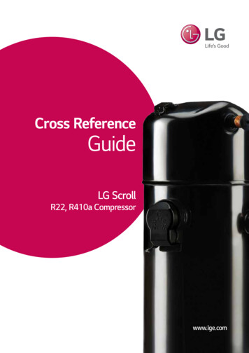
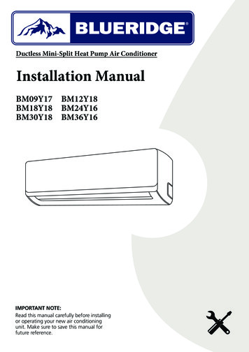
Parts NameIndoor Unitair inletpanelfilteraux. buttonhorizontal louvercoolingindicatorreceiverwindowair TURBOON/OFFMODE SAVE-FANSWINGSLEEPTIMERLIGHTX-FANremote controllerOutdoor Unitair inlethandleair outlet3
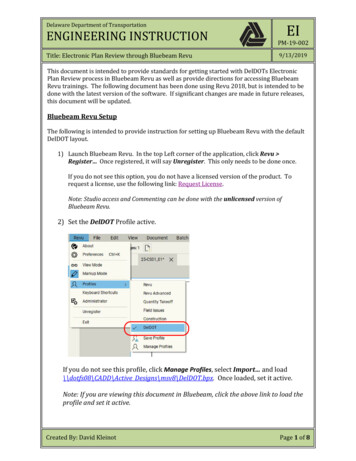
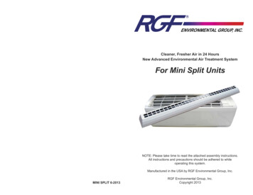
At least 15cmSpace to the ceilingInstallation dimension diagramSpace to the wallAt least 15cmAt least 15cmactheotrbsuctionSpace to the obstructionSpoetleatheto neac ctioSp strustobleaAt cm30At least 50cmEnglishAtSpace to the floorcm003stDrainage pipeAt least 30cmSpace to thSpatceotheoAt least 250cmSpace to the walle walltrbsAtuctionAt least 50cmcm002stSpace to theobstructionlea4
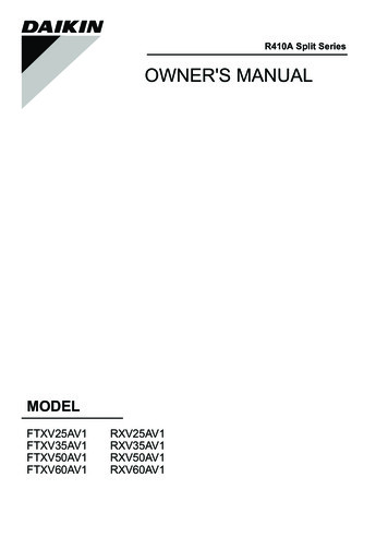
Tools for installation1 Level meter4 Drill head7 Open-end wrench10 Vacuum pump13 Inner hexagon spannerNote:2 Screw driver3 Impact drill5 Pipe expander6 Torque wrench8 Pipe cutter9 Leakage detector11 Pressure meter12 Universal meter14 Measuring tape Please contact the local agent for installation. Don’t use unqualified power cord.Basic requirementInstalling the unit in the following placesmay cause malfunction. If it isunavoidable, please consult thelocal dealer:1. The place with strong heat sources,vapors, flammable or explosive gas,or volatile objects spread in the air.2. The place with high-frequencydevices (such as welding machine,medical equipment).3. The place near coast area.4. The place with oil or fumes in the air.5. The place with sulfureted gas.6. Other places with specialcircumstances.7. The appliance shall not be installed inthe laundry.Indoor unit1. There should be no obstruction nearair inlet and air outlet.2. Select a location where thecondensation water can be dispersedeasily and won't affect other people.3. Select a location which is convenientto connect the indoor unit and near thepower socket.4. Select a location which is out of reachfor children.5. The location should be able towithstand the weight of indoor unit andwon't increase noise and vibration.6. The appliance must be installed 2.5mabove floor7. Don't install the indoor unit right abovethe electric appliance.8. Please try your best to keep awayfrom fluorescent lamp.Outdoor unit1. Select a location where the noise and outflow air emitted by the outdoor unit willnot affect the neighborhood.2. The location should be well ventilated and dry, in which the outdoor unit won't beexposed directly to sunlight or strong wind.3. The location should be able to withstand the weight of outdoor unit.4. Make sure that the installation follows the requirements of installation dimensiondiagram.5. Select a location which is out of reach for children and far away from animals orplants.If it is unavoidable, please add the fence for safety purpose.5EnglishSelection of installation location
Requirements for electric connectionEnglishSafety precaution1. The electric safety regulations must be followed when installing the unit.2. According to the local safety regulations, use qualified power supply circuitand earth leakage circuit breaker.3. Make sure the power supply matches with the requirement of air conditioner.Unstable power supply or incorrect wiring may result in electric shock, fire hazardor malfunction. Please install proper power supply cables before using the airconditioner.4. Properly connect the live wire, neutral wire and grounding wire of power socket.5. Be sure to cut off the power supply before proceeding any work related toelectricity and safety.6. Do not put through the power before finishing installation.7. If the supply cord is damaged, it must be replaced by the manufacturer, its serviceagent or similarly qualified persons in order to avoid hazard.8. The temperature of refrigerant circuit will be high, please keep the interconnectioncable away from the copper tube.9. The appliance shall be installed in accordance with national wiring regulations.Grounding requirement1. The air conditioner is the first class electric appliance. It must be properlygrounded with specialized grounding device by a professional. Please make sureit is always grounded effectively, otherwise it may cause electric shock.2. The yellow-green wire in air conditioner is grounding wire, which can't be used forother purposes.3. The grounding resistance should comply with national electric safety regulations.4. The appliance must be positioned so that the plug is accessible.5. An all-pole disconnection switch having a contact separation of at least 3mm inall poles should be connected in fixed wiring.6. Be sure to install an earth leakage breaker capable of handling maximum ratedcurrent. (One that can handle higher harmonics.)6
Installation of indoor unitStep one: choosing installation locationRecommend the installation location to the client and then confirm it with the client.Step two: install wall-mounting frameStep three: open piping hole1. Choose the position of piping hole according to the direction of outlet pipe.The position of piping hole should be a little lower than the wall-mounted frame,shown as below.WallSpaceto thewallabove150mmLevel meterMark in the middle of itWallSpaceto thewallabove150mmRightLeftø55mm or ø70mmø55mm or ø70mm(Rear piping hole)(Rear piping hole)2. Open a piping hole with the diameter of Ø55 or Ø70 on the selected outlet pipeposition. In order to drain smoothly, slant the piping hole on the wall slightlydownward to the outdoor side with the gradient of 5-10 .7English1. Hang the wall-mounting frame on the wall; adjust it in horizontal position with thelevel meter and then point out the screws fixing holes on the wall.2. Drill the screw fixing holes on the wall with impact drill (the specification of drillhead should be the same as the plastic expansion particle) and then fill the plasticexpansion particles in the holes.3. Fix the wall-mounting frame on the wall with tapping screws (ST4.2X25TA) andthen check if the frame is firmly installed by pulling the frame. If the plasticexpansion particle is loose, please drill another fixing hole nearby.
Installation of indoor unitPiping holeModelØ55Cooling capacity 6000WØ70Cooling capacity 6000WNote: Pay attention to dust prevention andtake relevant safety measures whenopening the hole. The plastic expansion particles arenot provided and should be boughtlocally.ø55/ø705-10EnglishStep four: outlet pipe2. When selecting leading out thepipe from left or right, please cut offthe corresponding hole on thebottom case.1. The pipe can be led out in thedirection of right, rear right, leftor rear left.leftrightleftrear rightrightrear leftcut offthe holeStep five: connect the pipe of indoor unit1. Aim the pipe joint at the correspondingbellmouth.pipe joint2. Pretightening the union nut with hand.union nutpipe3. Adjust the torque force by referring to the following sheet. Place the open-endwrench on the pipe joint and place the torque wrench on the union nut. Tightenthe union nut with torque wrench.8
Installation of indoor unitopen-endwrenchunion nuttorque wrenchpipeindoor pipeHex nut diameter Tightening torque (N·m)Ø615 20Ø 9.5230 40Ø 1240 55Ø 1660 65Ø 1970 754. Wrap the indoor pipe and joint ofconnection pipe with insulating pipe,and then wrap it with tape.Englishinsulating pipeStep six: install drain hose1. Connect the drain hose to the outlet pipe ofindoor unit.outlet pipedrain hose2. Bind the joint with tape.tapeoutletpipeNote: Add insulating pipe in the indoordrain hose in order to preventcondensation. The plastic expansion particlesare not provided.drain hosedrain hoseinsulating pipeStep seven: connect wire of indoor unitpanelscrew1. Open the panel, remove the screw onthe wiring cover and then take downthe cover.wiring cover9
Installation of indoor unit2. Make the power connection wire gothrough the cable-cross hole at the backof indoor unit and then pull it out from thefront side.cablecross holepower connectionwire3. Remove the wire clip; connect the powerconnection wire to the wiring terminalaccording to the color; tighten the screwand then fix the power connection wirewith wire clip.wiring boardOutdoor unit connection(for reference)3EnglishN(1) 2groundingwireN(1)23blue black brownyellowgreenwire clipNote: the wiring board is for reference only,please refer to the actual one.4. Put wiring cover back and then tighten the screw.5. Close the panel.Note: All wires of indoor unit and outdoor unit should be connected by a professional. If the length of power connection wire is insufficient (see table below), pleasecontact the supplier for a new one. Avoid extending the wire by yourself.Class:Length of Connecting Wire (mm)251800351800501800601800 A circuit breaker must be installed for the air conditioner in serial connection.10
Installation of indoor unitStep eight: bind up pipe1. Bind up the connection pipe, powercord and drain hose with the band.indoor unitconnection pipedrain hosebandindoor andoutdoor power cordgaspipe3. Bind them evenly.4. The liquid pipe and gas pipe shouldbe bound separately at the end.Note: The power cord and control wirecan't be crossed or winding. The drain hose should be boundat the bottom.banddrain hose2. Reserve a certain length of drain hoseand power cord for installation whenbinding them. When binding toa certain degree, separate the indoorpower and then separate the drainhose.Step nine: hang the indoor unit1. Put the bound pipes in the wall pipe and then make them pass through thewall hole.2. Hang the indoor unit on the wall-mounting frame.3. Stuff the gap between pipes and wall hole with sealing gum.4. Fix the wall pipe.5. Check if the indoor unit is installed firmly and closed to the wall.indoorwall pipeupper hookoutdoorsealing gumlower hook ofwall-mounted frameNote: Do not bend the drain hose too excessively in order to prevent blocking.11Englishindoor power cordliquid pipe
Installation of outdoor unitStep one: fix the support of outdoor unit(select it according to the actual installation situation)1. Select installation location according to the house structure.2. Fix the support of outdoor unit on the selected location with expansion screws.EnglishNote: Take sufficient protective measurementswhen installing outdoor unit. Make sure the support can withstand atleast four times of the unit weight. The outdoor unit should be installed at least3cm above the floor in order to install drainjoint. For the unit with cooling capacity of 2300W 5000W, 6 expansion screws are needed;for the unit with cooling capacity of 6000W 8000W, 8 expansion screws are needed;for the unit with cooling capacity of 10000W 16000W, 10 expansion screws areneeded.Step two: install drain joint(Only for cooling and heatingunit)Step three: fix outdoor unit1. Place the outdoor unit on thesupport.2. Fix the foot holes of outdoor unitwith bolts.1. Connect the outdoor drain joint intothe hole on the chassis, as shown inthe picture below.2. Connect the drain hose into thedrain vent.drain ventDrain hoseat least 3cm above the floorfoot holesfoot holeschassisoutdoor drain joint12
Installation of outdoor unitStep four: connect indoor and outdoor pipes1. Remove the screw on the righthandle of outdoor unit and thenremove the handle.3. Pretightening the union nut withhand.pipe jointscrewyellowgreenhandle4. Tighten the union nut with torquewrench by referring to the sheetbelow.Hex nut diameterliquid pipeØ6Ø 9.52Ø 12Ø 16Ø 19gas pipeliquidvalvegas valveTightening torque(N·m)15 2030 4040 5560 6570 75Step five: connect outdoor electric wire1. Remove the wire clip; connect thepower connection wire and signalcontrol wire (only for cooling andheating unit) to the wiring terminalaccording to the color; fix them withscrews.wiring boardIndoor unit connection(for reference)groundingwireblueN(1) 2handle3wire clip13black brownyellowgreenEnglish2. Remove the screw cap of valve andaim the pipe joint at the bellmouth ofpipe.union nut
Installation of outdoor unit2. Fix the power connection wire and signal control wire with wire clip (only forcooling and heating unit).Note: After tightening the screw, pull the power cord slightly to check if it is firm.Step six: neaten the pipesEnglish1. The pipes should be placed along the wall,bent reasonably and hidden possibly. Min.semidiameter of bending the pipe is 10cm.2. If the outdoor unit is higher than the wallhole, you must set a U-shaped curve in thepipe before pipe goes into the room, inorder to prevent rain from getting into theroom.wallU-shaped curvedrain hoseNote: The through-wall height of drainhose shouldn't be higher than theoutlet pipe hole of indoor unit. Slant the drain hose slightlydownwards. The drain hose can't becurved, raised and fluctuant, etc.the drain hosecan’t pointupwardsThe drain hose can’t be fluctulant The water outlet can't be placed inwater in order to drain smoothly.The drain hosecan’t befluctulantThe water outletcan’t be placed inwater14The wateroutlet can’tbe fluctulant
Vacuum pumping1. Remove the valve capson the liquid valve andpiezometerliquid valveLoHigas valve and the nut ofrefrigerant charging vent.gas valve2. Connect the chargingvalve caphose of piezometer torefrigerant chargingthe refrigerant charging ventvent of gas valve andnut of refrigerantcharging ventthen connect the othercharging hose to thevacuum pumpvacuum pump.3. Open the piezometercompletely and operateinner hexagonfor 10-15min to check ifspannerthe pressure ofpiezometer remainsclosein -0.1MPa.open4. Close the vacuum pumpand maintain this statusfor 1-2min to check if thepressure of piezometerremains in -0.1MPa.If the pressure decreases, there may be leakage.5. Remove the piezometer, open the valve core of liquid valve and gas valvecompletely with inner hexagon spanner.6. Tighten the screw caps of valves and refrigerant charging vent.Leakage detection1. With leakage detector:Check if there is leakage with leakage detector.2. With soap water:If leakage detector is not available, please use soap water for leakage detection.Apply soap water at the suspected position and keep the soap water for morethan 3min. If there are air bubbles coming out of this position, there's a leakage.15EnglishUse vacuum pump
Check after installation Check the following requirements after finishing installation.Items to be checkedPossible malfunctionHas the unit been installed firmly?The unit may drop, shake or emit noise.Have you done the refrigerant leakagetest?It may cause insufficient cooling(heating) capacity.Is heat insulation of pipeline sufficient?It may cause condensation and waterdripping.Is water drained well?It may cause condensation and waterdripping.EnglishIs the voltage of power supply accordingIt may cause malfunction or damage theto the voltage marked on theparts.nameplate?Is electric wiring and pipeline installedcorrectly?It may cause malfunction or damage theparts.Is the unit grounded securely?It may cause electric leakage.Does the power cord follow thespecification?It may cause malfunction or damage theparts.Is there any obstruction in the air inletand outlet?It may cause insufficient cooling(heating) capacity.The dust and sundries caused duringinstallation are removed?It may cause malfunction or damage theparts.The gas valve and liquid valve ofconnection pipe are open completely?It may cause insufficient cooling(heating) capacity.Test operation1. Preparation of test operation The client approves the air conditioner. Specify the important notes for air conditioner to the client.2. Method of test operation Put through the power, press ON/OFF button on the remote controller to startoperation. Press MODE button to select AUTO, COOL, DRY, FAN and HEAT to checkwhether the operation is normal or not.16
Configuration of connection pipe1. Min. length of connection pipe is 3m.2. Max. length of connection pipe and max. height difference.25 class9000Btu/h(2637W)35 class12000Btu/h(3516W)50 class18000Btu/h(5274W)60 class24000Btu/h(7032W)Max lengthof connection pipeMax city3. The additional refrigerant oil and refrigerant charging required after lengtheningconnection pipe The calculation method of additional refrigerant charging amount (on the basisof liquid pipe):Additional refrigerant charging amount extra length of liquid pipe additionalrefrigerant charging amount per meter When the length of connection pipe is above 10m, add refrigerant according tothe extra length of liquid pipe. The additional refrigerant charging amount permeter is different according to the diameter of liquid pipe. See the followingsheet. Additional refrigerant charging amount for R22, R407C, R410A and R134aDiameter of connection pipeLiquid pipe(mm) Gas pipe(mm)Ø6Ø9.52 or Ø12Ø6 or Ø9.52Ø16 or Ø19Ø12Ø19 or Ø22.2Outdoor unit throttleCooling only(g/m) Cooling and heating(g/m)152015503012017
Pipe expanding methodNote:Improper pipe expanding is the main cause of refrigerant leakage. Please expandthe pipe according to the following steps:A: Cut the pipeE: Expand the port Confirm the pipe length according to Expand the port with expander.the distance of indoor unit andhardoutdoor unit.mold Cut the required pipe with pipe cutter.expanderpipepipepipe cutterunevenburrEnglishleaningNote: "A" is different according to thediameter, please refer to the r diameter(mm)B: Remove the burrs Remove the burrs with shaper andprevent the burrs from getting intothe pipe.Ø6 - 6.35(1/4")Ø9.52(3/8")Ø12 - 12.7(1/2")Ø15.8 - 16(5/8")pipeshaperdownwardsF: Inspection Check the quality of expanding port.If there is any blemish, expand theport again according to the stepsabove.smooth surfaceC: Put on suitable insulating pipeD: Put on the union nut Remove the union nut on the indoorconnection pipe and outdoor valve;install the union nut on the pipe.union pipeimproper expandingleaningthe length is equalpipe18damagedsurfacecrackuneventhickness
Buttons on remote controllerON/OFF buttonMODE button /- buttonFAN buttonSWING buttonSAVE buttonX-FAN buttonTIMER buttonSLEEP buttonLIGHT buttonIntroduction to icons on display screenChild LockDry modeAuto modeSet tempCool modeHeat modeFan modeX-fanUp & down swingSleep modeSet timeTimer ON/Timer OFF19Fan speedEnglishTURBO button
Introduction to buttons on remote controllerNote: After putting through power, the air conditioner will give out a sound and operationindicator " " is ON (red indicator). You can operate the air conditioner throughthe remote controller. At ON status, after pressing a button on the remote controller, the signal icon " "on the remote controller will flash once. The air conditioner will give out a sound,which indicates the signal has been sent to the air conditioner. At OFF status, display screen on the remote controller displays the settemperature. At ON status, display screen on the remote controller displays thecorresponding startup function icon.English1ON/OFF buttonPress this button to turn on or turn off the air conditioner. After turning on the unit,the operation indicator " " on the indoor unit is ON (blue indicator. Color may bedifferent for different models) and indoor unit gives out a sound.2MODE buttonPress this button to select your required operation mode. After selecting auto mode, the air conditioner will operate automatically accordingto ambient temperature. The set temperature can’t be adjusted and also can’t bedisplayed. Press the "FAN" button to adjust fan speed. Press the "SWING" buttonto adjust swing angle. After selecting the cool mode, the air conditioner operates under cool mode. Thecool indicator " " on the indoor unit is ON. You can press the " " or "-" buttonsto adjust the set temperature. Press the "FAN" button to adjust fan speed. Pressthe "SWING" button to adjust the swing angle. After selecting the dry mode, the air cond
When installing or relocating the air conditioner, be sure to bleed the refrigerant circuit to ensure it is free of air, and use only the specified refrigerant (R410A). The presence of air or other foreign matter in the refrigerant circuit causes abnormal pressure rise, which may result in equipment damage and even injury.