Transcription
1Galaxy GRS s.r.o.of Liberec, Czech Republic,presents the life-saving:A new generation of rocket rescue parachutefor light aeroplanes in dire straits.Instruction Manual for Assembly and UseYou must follow these instructions for the system to work successfully.04/2016
2Legal noticeUnless these operating and handling instructions are adhered to, Galaxy GRS s.r.o. (Galaxy) cannotguarantee successful deployment of the GRS system and renounces any responsibility towards thesafety of persons handling the GRS system, and third parties involved.Anyone handling the GRS system must read, understand and honour the letter and intent of thismanual for assembly and operation. We would like to stress a few especially important items:1)2)3)4)5)6)7)8)9)10)11)12)13)14)15)16)Do not use the system in any way other than allowed by the manual.Do not under any circumstance take apart the GRS system.Do not disturb or remove detachable safety parts of the system, (these are red sealed, taped,wired or safe riveted) unless the installation procedure calls for it.The GRS unit must be handled as a pyrotechnical device and a loaded gun. It must not bepointed towards a person. Always keep the area in the firing direction clear.Do not activate the system after expiry of each 6-year service-cycle until renewed or anytimeafter the 30-year lifetime. Return the unit to the manufacturer for safe recycling.On installation the GRS unit becomes an integral part of an airframe but it is not deregisteredwith aircraft deregistration. At that time the owner must notify Galaxy and follow itsrequirements to dispose of the unit or to release it for duty on another airframe.Do not transport the system other than in the correctly labeled original transport box with themounted steel basket on the engine. The system must be secured by the transport safety A ofsteel wire of minimum diameter 2 mm and the transport safety B bolt M5. The launchinghandle must be secured by the peg with the warning flag.Before dismounting a GRS unit for any reason, the user must notify Galaxy, who will nominatean approved person to check the unit for proper securing for safe and legal storage ortransportation.Do not store the GRS unit below 14 or above 24 C, below 35% or above 73% humidity.Do not expose the system to high temperatures, hard impacts, mechanical damage, chemicals,or prolonged storage in excess humidity or a dusty environment.The GRS unit must not be subjected to vibration as from engine mounts or shocks as fromlanding gear.The GRS system must be firmly fixed to the airframe by at least four screws M6G8.Where the GRS system launching handle is accessible whilst the aircraft is on the ground, thehandle must be secured against incidental launching.After each 6-year system operational lifetime expiry or use, the rocket engine is replaced with anew one and the canopy is aired and repacked. The guarantee is renewed upon submission ofthe previous.Never place the GRS unit with the fire axis downward.It is forbidden to fly with secured system (the peg with the warning flag must not stay inside thelaunching handle during flight). When receiving the aircraft from the manufacturer make surethat the transport safeties A and B have been removed, as well as the safety steel basketcovering the rocket. Before flight you must remove the peg marked with a red flag with thewords "Remove before flight“ from the launching handle!" In case that you forget to removeany of these safety features it is not possible to activate the system and use it for rescue .Youcan lose your life!Galaxy – Liberec 11.09.2015
3Index1.2.3.3.Designation of our product: GRS, (rescue system), (system), (unit).2.1-Design, 2.2-Construction, 2.3-Operation, 2.4-Minimum height,2.5-Limitations,2.6-ComparisonConditions of storage and operation.Operation of the system GRS.Storage.Limitations.3.13.23.34. Classification of product for transportation purposes5. Packing of product and marking of product6. Installing the system6.16.26.36.46.56.6Before installationWhere to mount the GRSCovered exit apperturesPlacement of activation handleSafetiesChoosing the right GRS system for your aircraft7. Method for pre flight preparation of system and release of the safetymechanism7.1 Checking the activation handle of GRS system7.2 Checking the fastening of GRS system container on holder and aircraft7.3 Checking the fastening straps7.4 Checking the unwanted objects on GRS unit7.5 Placement of ignition switch7.6 Fire extinguisher8. Activation of the system in a hazardous situation8.1 Procedure in firing GRS unit8.2 After firing the system8.3 Effect of opening shock on aircraft and crew8.4 Inflating of parachute8.5 Possible emergency scenarios9. Warranty and service life9.1 Guarantee terms9.2 Using service life service life of six-year cycle10. Double securing against rocket firing11. Disposal of expired units12. Technical data13. Maintenance of system13.113.213.313.413.513.613.713.813.9Sheduled maintenanceMaintenance after damageOwner s maintenanceMoisture and other contaminantsPossible corrosion in activating handleUltraviolet degradationSoiling of the GRS unitProtection against incidental firing of the GRS unitMaintenance planning
41. Designation of our Product „GRS“and important information about the GRS systemDear Customer,Thank you for choosing a new GRS, which we made to the highest quality of its kind.Be assured it has undergone, on the basis of the Czech mining office delision, exacting examinationsin the Czech arms and ammunition testing station, examinations for the transportation ofexplosives according to classification of the UN, RID, ADR, ADN, and IATA - DGR and hasobtained the product type certificate with the issue of the type certificate by the LAA ČR on thebasis of the Office for civil aviation §81/2 no. 49/1997 of civil aviation from 03.21.1998, theGerman certification DULV Nr. R 21/ 01–1 Deutcher Ultraleichtflugverband e.V on01.10.2001 BAM and certification for import and use in the USA.Galaxy offers you a state of the art rescue system.The system is designed for the rescue of crew and aircraft, specifically for 1 and 2-seat light aircraft,ultralights and experimental aircraft and lately for General Aviation aircraft and unmanned aircraft.The product is certificated by LAA ČR, USA, Australia,Canada,South Africa and the DULV, BAMGermany and complies with the conditions for purchase of rocket systems in the trade net of ČR,USA and EC. The system has earned the patent certificate PV 1859-94.Galaxy GRS s.r.o. is based in Liberec, Czech Republic.Our local agents have the information, and the ear of the factory specialists with the knowledge, toget you the answer to any question.If you are not satisfied with service or pricing, please contact the factory:Galaxy Holding s.r.o.Tř, 1. Máje 24460 01 Liberec 3Tel/Fax: 420 485 104 492Mobil: 420 777 550 091e-mail: milan@galaxysky.czwebsite: www.galaxysky.cz
5Part 2. Design, Construction and Operation2.1 Design.The GRS system is designed for quick deployment to enable the rescue of crew and aircraftfrom the lowest possible height. In other systems the parachute is gradually pulled out from thetop, exposing the length of the material to distortion by air currents and damage by contact withairframe or detached parts thereof. The GRS canopy is kept contained in a harness until thesuspension ropes are fully extended at 15-18m above the airplane (depending on model), where it isthen extracted for safe inflation. This design minimises the danger of damage to the fabric andsuspension ropes during deployment. Inflation of the canopy starts in 0,4 to 0,7 seconds fromactivation of the system. The system is designed with reserve capacity to work even under extremeconditions.2.2.1 In a special container or in a special sleeveNew series of parachutes is tested at speeds of 305 kph so that the safety coefficient complies with1,5 multiple of aircraft operational limits for General Aviation.2.2 Construction.The GRS system (hard) container is made of a dural tube with front and rear detachable laminatedomes. Mounting points are provided on the lower sides of the dural tube. The canopy is folded intoa harness which slides into the container. The rocket tube is mounted on top and protected by alaminate cover. The rocket engine is connected to the harness by slings and to the firing handle by acable shielded to withstand stretching up to 120 kg. The handle is secured against incidental firingby a safety cable.2.3 Operation.The system is activated mechanically by pulling the handle with a force of about 11kg.The firing switch is displaced and two igniters are fired by a double striker which ignites the powderload which ignites the TPH (solid fuel) of the rocket engine. The rocket engine accelerates out of therocket tube, punches through the protective covers, pulling out the inner container with the rescueparachute above the aircraft. During launch there is minimal recoil and, unlike in other systems, theflame in the launching tube is not thrown forward, but is freely released through the rear into theexhaust tube. The GRS system uses rocket thrust instead of the closed-tube shell grenade recoildesign of other systems. In less than a second the parachute suspension ropes are fully extended andthe parachute is pulled out of the harness. The rocket engine carries the harness onward until its fuelis exhausted when it falls back to earth under a small parachute. Depending on the model, the maincanopy of the rescue system is open and fully inflated 50-60 ft (15-18 m) in the direction offiring between 1.5–3.2 seconds after being activated. The rocket may be aimed in any direction, thebest being rearward and upwards if aircraft configuration allows. Illustration no. 1
62.4 Minimum height.You are warned that the minimum firing height of 100 ft (30 m) for canopy without slider(measured in 38mph (60km/h) in horizontal flight) and 200 ft (60 m) for canopy with slider maynot always be a safe height from which to fire the system because of rotation or tilt of the plane,when the minimum firing height may be 180-250 ft (60–80 m).Just before take-off, review the scenarios according to Part 8 that will indicate immediate activationof the GRS irrespective of height. Although the GRS system is the most up to date rescue device forcrew and aircraft, Galaxy GRS cannot guarantee a safe recovery under all conditions.2.5 Limitations.The GRS parachute rocket rescue system is designed for rescue from the lowest possible height butit is still a compromise. The faster the parachute is opened the greater the impact on the airplane.The more this impact is reduced, the more height is needed to open the chute.After extended testing Galaxy has arrived at the following solution:Trikes are now built such that the wing will not easily separate from the hanging undercarriagewith motor and crew. (Where a safety cable secures the wing to the undercarriage.) Accordingto experience and measurements, the falling speed of such a unit with stalled wing will notexceed 140 km/h. We can use the GRS3 canopy up to 160 km/h, which enables the crew rescuefrom the minimal height of 90–150 ft (30–50m), but with severe stress on opening, or theGRS4/5 canopy with slider up to a speed of 260 km/h with less stress on opening, but at ahigher rescue height of 180-240 ft. (60–80 m). It is always necessary for the crew to use fourpoint belts. The stress on the airframe is 3.5–5.5G.Slower 3-axis 2-seat microlights may use the GRS3 system with reinforced canopy and fastslider which guarantees ability to rescue the crew at speeds up to 190 Km/h from a height of150-250 ft. (45–75m) provided the aircraft will remain in one piece under a stress of 5.5G.In other 2-seat planes, especially with low wings, it is necessary to use the system GRS 5 –6for speeds up to 260 km/h.(and 1-seat planes GRS 4–230 km/h, GRS 5–250 km/h). Thenew series of parachutes is tested at speeds up to 305km/h so that the safety factor 1.5complies with operational limits of airpalns for General Aviation. This is necessary due tothe sudden speed increase in the event of failure of a wing or a critical structural member. Theminimal height of use would then be 180–240 ft. (60-80m) and the stress on opening can be 3.5– 5.5 G. This canopy is equipped with a slider to decrease the stress on opening.Galaxy has gone to great lengths in developing the canopy slider to ensure safe canopy openingnot only in high speeds, but also quick opening at minimal speeds at low height above ground.This guarantees maximal chance of crew rescue with comparatively low deceleration stress.Another important point is packing pressure. Galaxy packs the canopy into its containerunder low pressure, which will not cause sticking of single canopy fields to each other as mighthappen when packing under high pressure. The container volume is about 10% more, but this iscompensated for by quick and reliable canopy opening.The GRS system is not a panacea for poor piloting, inexperience or flying into extremeconditions. The GRS will not make you a safer pilot. It simply provides a chance to save livesin certain hazardous circumstances. It is only part of an overall program of aviation safety, asairbags are to motorcar safety.The firm GALAXY cannot guarantee that you will not be injured after deployment orthat aircraft will not be damaged. While using a GRS unit could indeed save your life, onlyyou are responsible for the safe operation of your aircraft. You have a GRS only for additionalsecurity in the event that your skills, planning, judgement or careful equipment maintenancehave failed to avoid a hazardous situation.
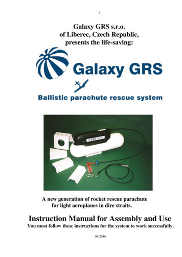
7When you use an emergency parachute system you may enter an unpredictable situation but thechances of saving your life are much higher than without it.Do not even think about testing your GRS system in enclosed spaces (hangar, room) to seewhether it works. The necessity to recharge the system (by returning it to the manufacturer) andthe danger to your safety and the safety of your surroundings, make such a test inappropriate anddangerous!2.6 Comparison–a parachute deployed by hand from a falling aircraft would take about8 seconds to fully inflate. At 140 km/h this translates to 300m or 1000ft. The GRS rescuesystem on the other hand needs only from 1.5 to 2.9 sec. This comparison alone presentssufficient reason for installing the system for the safety of pilot and aircraft.Part 3. Conditions of storage and operation3.1 Operation of the system GRS - the system is manufactured for an operational life of 30years under conditions of good maintenance and checks as given in the manual delivered withthe system. In the event that the system has not been fired after 6 years, the owner is obliged toreturn the system to the manufacturer for service. The product is dismantled, the canopy is airedand repacked, all components are checked and the rocket motor is replaced by a new one. (theoriginal is completely overhauled)3.2 Storage – if the customer is not able to mount it on the aircraft immediately, the six yearservice cycle still applies. The system must be stored in the transport cover so that it cannot betampered with or accidentally activated. The system must be stored in the steel transport basketand with the transport safety A from steel wire of 2 mm diameter and transport safety B, boltM5 and attach mouting (peg with little flag in handle).Do not expose the system to temperatures below -400C or above 600C.Optimal storage temperature is 14–240 C and 35–73 % humidity.Where the aircraft environment is likely to exceed these parameters for an extended time, theunit must be dismounted and stored in a climate controlled room.3.3 Do not expose the system to high temperatures, impacts, vibrations, mechnical tampering,contaminants, aggressive chemicals, or store it in an area of high humidity.Respect the system like a pyrotechnical device and never point it at a person.Do not allow anyone in the direction of firing. Treat it as you would a loaded gun.Part 4. Classification of product for transportation purposeThe Czech shipping and industrial register has issued a ruling classifying the GRS as dangerousgoods of the class 1- explosive, in accordance with the International Maritime Dangerous GoodsCode (IMDG CODE) under the designation UN no. 0453, classification code 1.4 G . Thisnumber is changed every year after successful re-test and paperwork.Part 5. Packing of product and marking of productThe GRS transportation box is marked with a label valid for the year of shipment. To ship theunit in a subsequent year, you must get a new label from Galaxy and affix it over the old.
8Illustration no 2: Typical safety devices for transporTransport saf1. Safety A- of steel wire diameter 2 mm ,B M5 bolt.2. Transport steel basket.3. Operational safety pin with little flag.4. Transport screws 2 x M5.You must get updated advice from the factory before shipping.Part 6. Installing the system6.1 Before installation the user must read and understand this manual. Failure to do this oroverlooking important information while installing or maintaining the system in accordancewith the instructions and advice in this manual could result in personal injury or death to you oryour passangers and damage to your aircraft. If you have any questions or are unsure of any partof this manual, get advice from an agent or the factory before proceeding.Galaxy wishes you to fully understand the proper use of the GRS for your safety and that ofyour passengers. Do not replace any part with a similar part you may have obtained elsewhere.The manual is explicit in the proper mounting procedures required for safe installation and inthe proper use of the system. Do not under any circumstances vary from the described methodsor components supplied without first getting approval from Galaxy.6.2 Where to mount the GRS: The weight of the system may shift the center of gravity of theaircraft in an undesirable or desirable way. Before fitting, new weight and balance calculationsmust be made and checked against the aircraft manual for safety.The GRS when fitted may aim in any direction, but any downward firing angle will sacrificeprecious height, raising the minimum safe deployment height. Regarding the direction of fire,Galaxy philosophy is different to other similar rescue systems. The GRS unit is equipped with avery strong rocket engine which quickly pulls the complete canopy to the limit of its suspensionropes and releases it for inflation in the minimum possible time. Thus, if the rocket is launchedvertically, the deployment height is effectively increased by 60ft.Since many low-altitude emergency scenarios would pitch the aircraft steep downwards, abackward upward launching angle is a good choice where aircraft configuration allows.Working with manufacturers, optimum mounting positions have been developed for manypopular aircraft. Mounting your GPS to factory specification greatly simplifies fitting, andreduces paperwork to have the installation accepted by the Civil Aviation Authority.Do not install the GRS where it will be subjected to shock or vibration, like onundercarriage or engine mounts. Do not mount it pointing down.Mount the system so that no fuel or humans will be in line behind the rocket exhaust, evenwhere normally protected by structure.
9The angle of fire must be well clear of the propeller arc .On pusher aircraft the drawn sling mustbe equipped with a steel cable, thick enough to not be severed by the propeller, and long enoughto prevent the drawn sling to contact the propeller. Direction of deployment must avoid areasthat might become obstructed by a failed wing. Mount the container firmly to a solid part of theairframe with well engineered hardware.Observe a clear gap of at least 30 mm around the perimeter of the deployment side of the unit toavoid the rocket or inner container contacting anything on departure.Of particular importance to installation inside an aircraft: (models IN or Soft)Be sure that the drawn sling, leading to the hang slings on the construction of aircraft, which isusually connected with a carbiner, will not impede on the course of the rocket or innercontainer. The slings must be diverted (e. g. with the help of PVC tapes) a minimum of 30 mmfrom the anticipated perimeter of the course of the container and rocket. It is forbidden to putany part of the hang slings on top of the container as well!The unextended length of the hang slings between anchor point and carbiner mounting must nothang loose. Do not roll them up, but double up as long as possible and fix to the constructionwith breakable fastenings like cable ties or adhesive tape.Each hang sling must encircle a stable anchor point or otherwise be prevented from slipping onits mounting tube. This allows the lengths of the slings to determine the aircraft pitch in descentunder canopy. It is forbidden to put any part of the hang slings on top of the container as well!The aircraft should always descend in a more or less horizontal position:a) A slightly nose-up descent will minimise the effect of arrival impact on the crew.b) On the other hand, a slightly nose-down descent might allow some aerodynamic control, givingthe pilot a chance to minimise airframe damage, but at a higher risk of crew injury.Illustration no. 3
106.3 Covered exit appertures.These specifications are crucial for the rocket to gain sufficient kinetic energy to breachthe cover and safely deploy the parachute.The rocket will break through a canvas fuselage covering on a perforated cross or tear away apatch affixed by a dry zip, but it will not break solid dacron or insufficiently perforatedperimeters. Perforations must be a maximum of 3 mm from each other with a minimumdiameter of 2 mm. Perforations may be covered with paint or adhesive foil.Do not perforate laminated parts – cut a hatch as allowed by the manufacturer and seal itwith foil. The force to detach the cover must not be more than 15kg. The hatch perimeter mustallow 30 mm or more clearance around unit projected area. In this case the minimum distanceof container cap from foil is 20 mm.Break-through cockpit glazing – Specifications must be sent to Galaxy for approval, and thecontainer cap to glazing clearance must be at least 100mm. Alternatively, a hatch can be cut outand sealed as with a laminated structure. The direction for safe firing is 90 to the glazing. Herewe specify GRS type IN with textile cap. Where the sling might be damaged by remainingglazing, use the steel connecting cable 40 KN fixed to the anchor point and the drawing sling ofthe parachute.Illustration no.4Note: Besides the perimeter perforation do not forget to do cross perforation where the rocketexits.The rocket exhaust tube must protrude at least 5mm through a fabric covered fuselage.Illustration no. 5During rocket firing high velocity particles are released. To protect against head or eyeinjury, the crew must be separated from an inside mounted GRS by a section wall, a seatrest or a custom fabric shield.
11Illustration no. 5bModification BModification ARocket engineThe rocket put freely to thetube including the nylon pegon the jet and fix the steeltapes by two rivetshooksAdhezivefolioInstallation of the exhausttube to the rocket engineRocket engineStronger hooksThe rocket put freely to the tubeincluding the nylon peg on thejetInside of fuselageWarning!Never tight it by a collar to therocket jetNote: This exhaust tube can be installed when the rocket is near to tank,crew.
126.4 Placement of activation handle.Mount the activation handle so that it is visible and accessible to both members of the crew.Consider that the possible distance to the launching handle is limited by tighten seat belts. It isforbidden to make loops with the bowden – the GRS system can not be activated when thebowden is looped! The smallest bend radius should be no less than 5 cm, lead the bowden asstreight as possible.The activation handle must not be close to other controls. There must be sufficient clearancearound the handle to allow easy grasping with a gloved hand. It should be placed so as to beclearly visible to the eyes of the crew, no extreme head rotation needed.For the safe activationthe pull of 5-7 cmof the activation handle is enough, but we recommend a free space of ca. 30cm for the free move of elbow. The cable in the bowden is pre-sprung in a loop which must bedrawn out completely to activate the system. The bowden must be routed and mounted such asto avoid sharp bends that might increase required pulling strain or even prohibit the system fromfiring. Cables must be neatly fixed to avoid tangling with moving parts or crew. Nuts must besecured against loosening. The bracket of the activation handle must be firmly mounted usingboth screw holes. If the bracket was to come adrift on pulling the handle, the system will not beactivated. For two M5 10.9 bolts use a tightening torque 8,5 Nm.6.5 Safeties.During transport the system is secured by transport safeties A and B (which are connected byred ribbon), safety steel basket and the peg with the warning flag on the launching handle.Before system installation you must unscrew the transport safety B. Keep the transportsafety A activated (needle in the front of the rocket). The red ribbon will inform you that thesafety A is still activated during the whole process of system installation. When the installationis completed the transport safety A must be snipped and completely removed with the redribbon. After this step the system is secured by the operating safety only - peg with the warningflag on the launching handle.When the system is mounted on aircraft as well as the launching handle, follow the instructionson the labels and sketches in the manual, all transport safeties must be removed and stored forreturn shipping to us for system revision. After another final check of the installation, cut andremove the red thread securingthe safety peg, and the system is operational.The safety peg must be removed only when the aircraft is ready for take-off, andre-inserted immediately upon completion of every flight. It is a good idea to make the safetypeg the last item on your pre-flight checklist and the first on your shut-down checklist after theaircraft has come to a stop. This will avoid the danger of clothing, straps or the like catching onthe release handle during aircrew boarding or disembarking or while air or ground crew arefiddling with equipment like safety belts and headsets.Where the aircraft is left unattended with the release handle reachable, the safety peg itself must
13be secured by a lock or split ring.Bolts M6G8 used in the container installation are treated with silicon cement before installationand fitted with nylock nuts. Other bolts are fastened with Loctite 243. This product is a complextechnical device and for its proper function, professional installation by a trained person isrequired for both initial installation and inspection.Illustration no. 6Do not remove beforeinstallation is completed.6.6. Choosing the right GRS system for your aircraft.Please refer to illustration no 18: Technical data chart.1) Choose the canopy size according to the maximum permitted take-off weight specified foryour aircraft. You may choose a unit with bigger than minimum size.2) Choose the maximum deployment speed, according to these criteria:a) For trikes or powered paraglider there are these possibilities:A system designed for deployment at speeds up to 160 Km/h is quite adequate provided thewing remains attached.It is possible as well to use reinforced canopy to allow up to190Km/h equipped with quick slider. These systems provide the lowest deployment heightat the cost of higher stress on openingA GRS 5 –6 canopy with slider will allow deployment at up to 320 Km/h, which is morethan expected terminal speed, but at the cost of a higher minimum deployment height.b) For fixed wing aircraft the system is chosen on wing loading. This is because a highwingload aircraft will accelerate quicker upon loss of lift or loss of a control surface. Forlightly loaded craft, generally made of tube and covered in Dacron, we recommend the newcanopy with quick slider, reinforced for up to 190 km/h. For sleek & clean craft with highwing loadings, mostly covered in ceconite or glass fibre, you should specify GRS 4 or 5 or 6with slider for up to 320 km/h deployment speed.3) Choose a type according to installation environment. Galaxy now produces 2 sizes of duralcontainers, 185 mm diameter, equipped with 3 basic mounts, 1(a/b), 2 or 3(a/b), modified asnecessary. Also produced are several sizes and types of SOFT packages which may be placedinto a box in the aircraft, or fixed to it by slings and loops.I. Type: OUT for exposed installation.An order designation example: for a trike up to 350kg maximum weight, would be:GRS 350/160 OUT (alternative, GRS 350/190 OUT or GRS 450/160 OUT)Then specify a holder and its placement (holder no. 1,2,3 (a/b)And equipment (length of cable and bowden) See illustrations no. 7,8,10II. Type: IN is packed in a container with a fabric cap, suitable for enclosed installations.This is recommended where the mounting position is securely dry.An order designation example: for a fixed wing aircraft of max weight 450 kg:
14GRS 450/260 IN (alternative: GRS 450/190 IN or GRS 525/240 IN)Then specify a holder and its placement (holder no 1,2,3 (a/b)also angle holder, and length of firing bowden.finally: slings, number, length and strength. See illustration no. 11.With types I and II the holders are fixed to the containers, thereby limiting the containermounting positions. The mounting position must thus be specified with the order.III. Type: IN“SOFT“ – is designed mostly for inside installation – its inner container is made offabric and equipped with slings for fixing into aircraft. By means of slings and buckles
Galaxy GRS s.r.o. is based in Liberec, Czech Republic. Our local agents have the information, and the ear of the factory specialists with the knowledge, to get you the answer to any question. If you are not satisfied with service or pricing, please contact the factory: Galaxy Holding s.r.o. Tř, 1. Máje 24 460 01 Liberec 3 Tel/Fax: 420 485 .