Transcription
Arctic EngineeringModule 8Slide scriptWelcome to this Module – an overview of cold regions utilities. This module will provide a general introduction to coldregions utilities design and construction, along with some issues associated with project planning and development. Moretechnical details are available in a new UAA course, CE A684 Arctic Utilities Design, offered each spring semester as aDistance Ed course.Page 1 of 62
Arctic EngineeringModule 8Slide scriptThis module serves as an introduction. You can read through the slides at your own pace. The emphasis is on ruralAlaska, but the same principles and procedures apply to resource development facilities or other locations which fallunder the definition of cold regions.Page 2 of 62
Arctic EngineeringModule 8Slide scriptEach of the cold region countries have unique approaches to design and constructing utilities, but our focus will be onAlaska. Although the majority of slides and pictures will be from rural Alaska, much can be applied to other non-ruralcommunities, or construction camps. This module is somewhat general, but serves to set the stage for many types ofutility projects. Details of utility design can be found in the American Society of Civil Engineers monograph, “Cold RegionsUtility Design”.Page 3 of 62
Arctic EngineeringModule 8Slide scriptThis is a partial listing of some of the issues that make utility design in cold regions, particularly Alaska, unique. Inparticular, the logistics of material and equipment transport, and the high cost of construction reinforce the need to payparticular attention to design and construction management.Page 4 of 62
Arctic EngineeringModule 8Slide scriptThis is a partial listing of some of the issues that make utility design in cold regions, particularly Alaska, unique. Inparticular, the logistics of material and equipment transport, and the high cost of construction reinforce the need to payparticular attention to design and construction management.Page 5 of 62
Arctic EngineeringModule 8Slide scriptThese are some of the fundamental objectives in the design and construction of cold regions utilities. They’re similar tothe more temperate locations. The third item above is particularly significant in rural Alaska, where the lack ofinfrastructure continues to have a direct impact on individual and public health.Page 6 of 62
Arctic EngineeringModule 8Slide scriptThe development of water and wastewater systems in the state, particularly in small rural communities, has developed atdifferent rates, and using different technologies. This module will give some background in the types of cold regionsutilities which have found successful application.Page 7 of 62
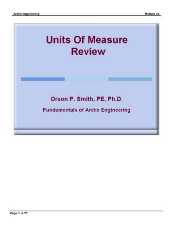
Arctic EngineeringModule 8Slide scriptThe majority of Alaska’s 600,000 people live in the larger population centers, like Anchorage, Juneau, Fairbanks, and thesurrounding subdivisions. There are about 300 communities, with about 100,000 people that live in isolated locationsscattered across the state. This graphic summarizes the condition of the approximately 300 communities in the state. Itshows the populations size, represented by the diameter of the circle, and the percent without fully running water andsewer in the houses. For the most part, the larger communities have had piped utilities for many years. With the exceptionof the farther north communities, conventional utility design has been used.Page 8 of 62
Arctic EngineeringModule 8Slide scriptFederal and state programs have been building utilities in Alaska since 1960, with over 1.5 billion expended to date. Anestimated additional 1.0 billion is needed to complete service. The communities vary in size from several dozen to 600 to1000 people, with an average of about 500 people. They developed differently over time – some of them historic, some ofthem recent. They exist in a variety of geographic conditions. Some are very linear, located along coastal or river systems,others are “clustered.” Many developed without consideration for water and sewer service.Page 9 of 62
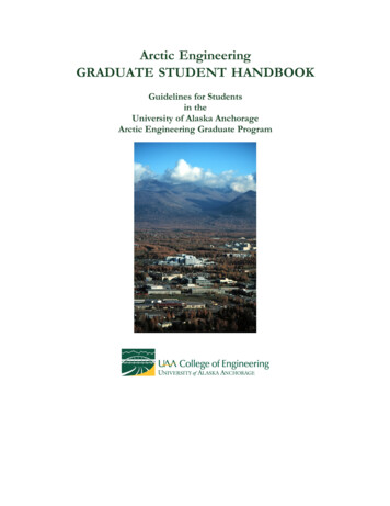
Arctic EngineeringModule 8Slide scriptThe main objective of providing water and removal of wastewater is health, with a number of secondary considerations,like convenience, comfort, economic growth and development. There is a minimum quantity of water that is needed for thefull health benefit of treated water to be realized. In addition, removal of human waste from contact and from the livingenvironment is also very critical. The graph on the left is from the Cold Regions Utilities Monograph, and is representativeof similar studies by the Public Health Service, World Health Organization (WHO), and Pan American Health Organization(PAHO).Page 10 of 62
Arctic EngineeringModule 8Slide scriptThe design engineer's role typically is focused on the first 4 items. The other 4 related to social-political factors, whichmake individual and community involvement in project planning very important if a project is to be successful.Page 11 of 62
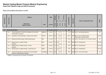
Arctic EngineeringModule 8Slide scriptBoth ground water and surface resources have been developed in cold regions. On a number basis, 80% of the watersystems in Alaska use groundwater sources, whereas on a population basis the majority of people use surface water.Lakes, ponds and rivers may be the only source of water in areas of deep permafrost, and may be preferred due to poorgroundwater quality. Numerous shallow ponds and lakes cover vast areas. Water quality may vary from pond to pond inthe same region. Some of the factors to consider for intake structures include protection from ice damage, flooding, andbank stability. Because of the high cost of permanent structures, many intakes are temporary (see photo left). Largerdemands usually require a permanent structure (photo right).Page 12 of 62
Arctic EngineeringModule 8Slide scriptBoth ground water and surface resources have been developed in cold regions. On a number basis, 80% of the watersystems in Alaska use groundwater sources, whereas on a population basis the majority of people use surface water.Lakes, ponds and rivers may be the only source of water in areas of deep permafrost, and may be preferred due to poorgroundwater quality. Numerous shallow ponds and lakes cover vast areas. Water quality may vary from pond to pond inthe same region. Some of the factors to consider for intake structures include protection from ice damage, flooding, andbank stability. Because of the high cost of permanent structures, many intakes are temporary (see photo left). Largerdemands usually require a permanent structure (photo right).Page 13 of 62
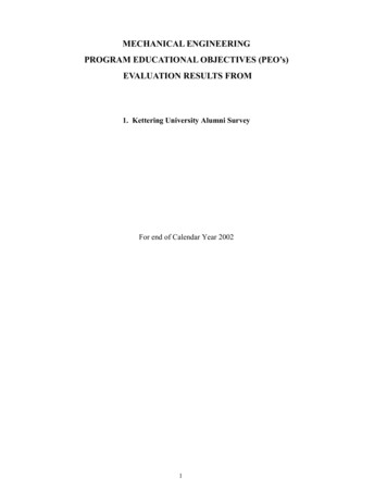
Arctic EngineeringModule 8Slide scriptIn areas where only seasonal frost occurs, the pipeline is buried below the frost line. In frozen ground, depths of 3-4 feetare common. The pipeline on the right has a glycol heat line to add heat to prevent the line from freezing.Page 14 of 62
Arctic EngineeringModule 8Slide scriptOver the years, different alternatives and levels of service have developed. This originally was planned as a phasedapproach, in which increments of improvement were built as funds from the federal and state government becameavailable, as the community government progressed, and as the individual’s ability to pay for service improved. The socialphilosophy in the US included the model that federal/state funds would provide capital construction funding, while the localgovernments would be responsible for operation, maintenance and continuing payments for upgrades and improvements.Page 15 of 62
Arctic EngineeringModule 8Slide scriptAt the lowest level of service, treated drinking water is provided at a central location such as a watering point, whereindividuals could come to haul water for consumption. A place was provided where wastewater (honey buckets) could bedisposed of. Water use was minimal (5 gallons per capita per day or less), as the effort and energy required to haul wateris high. Water reuse in the home, cross contamination, and contamination from open containers, many times spreaddisease. It did provide an improvement over hauling water from the slew or untreated source.Page 16 of 62
Arctic EngineeringModule 8Slide scriptIn those locations where the soil and site conditions limit conventional collection systems, honeybuckets are prevalent. A5-gallon bucket, with a plastic bag, and a toilet seat. Pinesol or lysol is added periodically to reduce odors.Page 17 of 62
Arctic EngineeringModule 8Slide scriptAn initial approach to community disposal was to provide wood bunkers where people could dispose of their buckets. Ofcourse, they filled up over time, and had to be relocated. High water table, and poor soils lead to both pollution and publichealth concerns, not to mention aesthetic considerations.Page 18 of 62
Arctic EngineeringModule 8Slide scriptAn alternative that was developed in the early 1980’s was the honeybucket bins – plastic, covered containers locatedthroughout the community. Waste was dumped into the HDPE bins. A ATV or snow machine would back up, and lift thebins. Contact with the waste was minimized.Page 19 of 62
Arctic EngineeringModule 8Slide scriptThe next service level developed was central washeterias. These industrial type buildings housed laundry facilities, toilets,showers, and saunas that were available for public use. During the summer months, a distributed watering point (asshown in the lower left hand photo), provided treated water closer to the home. Water use was greater (10-20 gallons percapita per day), and was an incremental improvement.Page 20 of 62
Arctic EngineeringModule 8Slide scriptIn the late 1960s, trucked vehicle haul of water was practiced in some locations. The high cost of delivery, equipmentupkeep, and the need to maintain roads, caused many to go into disuse. During the late 1980s and early 1990s, renewedemphasis on eliminating contact with water and wastewater lead to small vehicle haul systems, several examples areshown above. Water use was still meager, due to the cost of service. Building of gravel roads and boardwalks wasconsidered part of the project.Page 21 of 62
Arctic EngineeringModule 8Slide scriptLarger vehicle haul continues to be used at larger communities, or where roads are available and maintained. The pictureon the right shows an in-house holding tank at Galena, with small on-demand pressure pump below the tank. Thehousehold had hot and cold running water under pressure in the house. This method of service is common in theCanadian north.Page 22 of 62
Arctic EngineeringModule 8Slide scriptThe highest service level is piped utilities. Where larger quantities of water are required, pipes are the most economicalmethod of delivery, but also the most costly to construct, operate, and maintain. Large volumes of water also requiremethods of wastewater collection, treatment and disposal. The next few slides will cover piped utilities materials, methodsof water delivery, and associated appurtenances.Page 23 of 62
Arctic EngineeringModule 8Slide scriptThe most common material used for both water and wastewater is the arctic pipe. It has been in use for many years,using many different materials. It is a three part, manufactured material. The inner pipe is used for fluid transport. Up untilthe mid 1980’s, copper, ductile or PVC or other material was used as the inner pipe. After a series of tests done at UAAby the Public Health Service, both water and sewer were switched to high density polyethylene (HDPE), due to it’s abilityto withstand repeated freeze/thaw cycles without damage. Urethane foam is used for insulation, and the outer layer ofeither corrugated metal pipe (galvanized steel or aluminum), spray on coating, or HDPE used. The purpose of the outercoating is to protect the pipe, add structural strength, prevent moisture migration into the foam, and maintain straight piperuns. It is manufactured to specification, for various materials, material properties, dimensions, configurations. It’s usuallymanufactured in 20-ft lengths, but 40-feet lengths are available. Connection of joints is critical to maintain pipelineintegrity, as well as prevent moisture migration, and reduce heat loss.Page 24 of 62
Arctic EngineeringModule 8Slide scriptThere are 4-5 different suppliers, some in Alaska, Canada, and the lower 48. It can be bundled for shipment to the projectsite by air or barge. Because it is custom built, lead times are required.Page 25 of 62
Arctic EngineeringModule 8Slide scriptUtilidors can be designed for different configurations, with boardstock insulation installed. They’re designed for aboveground installation, as it is difficult to make water tight. Water and sewer along with heat and heat trace lines can beinstalled.Page 26 of 62
Arctic EngineeringSlide scriptThe utilidors can be “nested,” and shipped to the project site, where they can be field assembled.Page 27 of 62Module 8
Arctic EngineeringModule 8Slide scriptIn some projects, many different types of materials and carriers are used, depending on the needs and purposes of theparticular location. This slide shows a vacuum sewer system, along with circulating water lines in arctic pipe andaluminum utilidors in Savoonga on St. Lawrence Island.Page 28 of 62
Arctic EngineeringModule 8Slide scriptMany different modifications have been used, such as the integral glycol heat trace line shown in the upper photo. Arcticpipe can also be used as a carrier pipe (sometimes called a utiliduct).Page 29 of 62
Arctic EngineeringModule 8Slide scriptWhere soil conditions permit, buried utilities are preferred. Use of geo-textile materials, and board stock above the pipe tominimize depth of freeze, and below the pipe to reduce thawing of frozen ground are common. In many cases, due to thehigh moisture content of the soil, winter construction may be required.Page 30 of 62
Arctic EngineeringSlide scriptIn some locations, massive ice, thaw unstable soils, and logistics of construction, do not allow buried utilities.Page 31 of 62Module 8
Arctic EngineeringSlide scriptDrilled or driven piles for above ground installations have been used for many years.Page 32 of 62Module 8
Arctic EngineeringModule 8Slide scriptPiles can be expensive to install, and may require winter construction to get the equipment on to the frozen ground. Forwater lines, grade is not as critical as sewer mains. Mud sills are a low cost alternative. One of the issues of pipes on theground include the periodic movement due to freeze/thaw cycles. Spring breakup flooding require duckbill anchors tomaintain alignment.Page 33 of 62
Arctic EngineeringModule 8Slide scriptUnless properly designed, piles may settle or jack (as shown in the photo in the upper right). Helical piers or anchors havebeen used in the last 5 years to provide a stable ground support. UAA has an on-going research program into the use ofhelical piles in permafrost. The UAA class in Frozen Ground Engineering provides a module on helical pile design.Page 34 of 62
Arctic EngineeringModule 8Slide scriptOne of the major planning issues related to the fact that above ground utilities can create problems with human andvehicle movement. It can separate a community, create barriers, and reduce the aesthetic quality. During winter, snowaccumulation and barriers to snow machine transport occur.Page 35 of 62
Arctic EngineeringModule 8Slide scriptFive different types of water systems have been developed over the years, each with particular advantages anddisadvantages. All require the net addition of energy to prevent freezing.Page 36 of 62
Arctic EngineeringModule 8Slide scriptThe most common type of system in Alaska is the single main recirculating system or pitorifice system. It consists of aloop of arctic pipe or utilidor in which heated water is circulated in a loop. Heated water in the service line is induced by a“pitorifice” (see subsequent slides).Page 37 of 62
Arctic EngineeringModule 8Slide scriptPitorifices were developed in the 1950’s after research at Washington State University by the PHS Arctic Health Researchlab. Piped and circulating water systems installed in Fairbanks in the late 1950’s, and in the communities of Unalakleet,Holy Cross, Grayling, and many more locations. There are over 50 such systems now in use. Both an upstream anddownstream pitorifice are used. The constant flow of water induces flow into the service line.Page 38 of 62
Arctic EngineeringModule 8Slide scriptBoth single main direct bury arctic pipe, and above ground utilidors are used for circulating system. This slide shows amain-line service connection box for service to a house. Minimum flow velocities in the main line of about 2 feet persecond (0.60 meters per second) are required, and line lengths are limited to 100 feet, before circulation pumps arerequired. The right photo shows a small in-house circulation pump for a longer house service line.Page 39 of 62
Arctic EngineeringModule 8Slide scriptThe selection of system type, design and analysis is a combination of hydraulic, thermal, and economic considerations, aswell as other non-engineering issues.Page 40 of 62
Arctic EngineeringModule 8Slide scriptSome fairly sophisticated piping and controls are required for water distribution, beyond the treatment, pumping andpressure systems common on water systems. This photo shows one loop of a multiple loop circulating water system.Notice the meters, alarms, and methods of heat addition.Page 41 of 62
Arctic EngineeringSlide scriptThere are a number of unique features in water distribution systems as shown above.Page 42 of 62Module 8
Arctic EngineeringModule 8Slide scriptWater service lines usually require a supply and return line. Heat tape is typically provided at the connection to the housefor freeze prevention, and a longer heat tape for line thawing.Page 43 of 62
Arctic EngineeringModule 8Slide scriptThe connection to the house is critical. Access for turning service off, while maintain circulation is required, as is thetransition from a fixed, buried utility, to a structure that may periodically move under freeze/thaw soils conditions.Page 44 of 62
Arctic EngineeringModule 8Slide scriptFire protection and suppression is another critical issue in cold climates. Low humidity dries out building products, and thecontinuous use of heat such as wood burning stoves, oil burning heaters, etc. increase the risk of fire. Providing highvolumes of water through an arctic distribution system is difficult due to the system configuration, the method of operation,and the limited sizes of pipes to keep operation expenses low.Page 45 of 62
Arctic EngineeringModule 8Slide scriptIt is probable that all utilities may eventually freeze. System redundancy, increased reliability, multiple pumps andcomponents, and freeze “friendly” materials are all important, as is means of thawing. The above shows thaw ports forready access under winter conditions.Page 46 of 62
Arctic EngineeringModule 8Slide scriptWastewater disposal relies on natural processes for completion of the treatment process. Wetland treatment as beenused for many years in the form of tundra ponds and seasonal disposal to the tundra.Page 47 of 62
Arctic EngineeringModule 8Slide scriptWhich is the best option? That all depends on which of the above selection criteria proves most important. Many times,the treatment method and selection criteria are presented in a matrix, with points assigned to permit order ranking.Page 48 of 62
Arctic EngineeringModule 8Slide scriptNot surprising that the majority of treatment types in the state are lagoons and tundra ponds. A separate module part onlagoons will cover design and construction. The text has an excellent discussion of them.Page 49 of 62
Arctic EngineeringModule 8Slide scriptThere are many ways to
Arctic Engineering Module 8 Page 18 of 62 Slide script An initial approach to community disposal was to provide wood bunkers where people could di spose of their buckets. Of course, they filled up over time, and had to be relocated. High water table, and poor soils lead to both pollution and public