Transcription
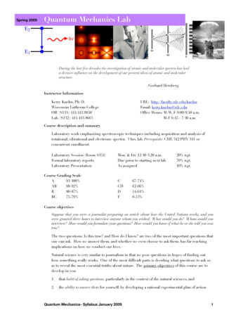
ELEC2501A – Lab 0LAB 0: Orientation to Remote Login and Multisim LiveDisclaimer: Any saved documents are not permanent on VLSI lab computersunless saved on the H: drive. Documents saved on drives other than H: will be erased.It is also suggested you save a backup on a networked platformsuch as OneDrive or Google DrivePurpose:This semester of ELEC 2501 is being delivered partially online, which includes the laboratory component. Asyou progress through the course you will be required to complete versions of the ELEC 2501 labs that havebeen modified in a way that they can be completed at your place of residence as long as you have a reliableinternet connection. This document is an introductory laboratory designed to get everyone familiar with the toolsyou will need throughout the term to complete the assigned lab component.This lab is not for credit; however, it is important to complete the exercises in this document before the end ofthe first week to ensure you have a base skill set to complete the core labs in an efficient and effective mannerstarting the second week. For more information about the expectations of each student regarding the labsplease refer to the course syllabus and ‘Student Expectations’ posted on Brightspace.You should complete Lab 0 at home during your scheduled lab time to become familiar with accessing theequipment remotely. Make sure to take screenshots your steps to confirm you have performed the lab whensubmitting to Brightspace.Resources Needed – these will be needed throughout the term(i)(ii)(iii)Device with Windows/Mac/etc. operating systemReliable internet connectionCarleton email address and passwordPart 1: Connecting to Carleton’s VPN (Virtual Private Network)A large portion of the laboratory component for this course will require you to have remote access to equipmentand devices on campus. To ensure the security of the university networks, all students registered in this coursewill be required to use Carleton’s VPN service for remote login purposes. To set this up go to this ess/Click on the instructions corresponding to your chosen operating system as shown in Figure 1.ELEC 2501 Lab 0Page 1 of 15
ELEC2501A – Lab 0Figure 1: Carleton Remote Access (VPN) WebsiteYou will be taken to a page providing instructions for you to set up your VPN based on your operating system.Once set up, you must connect to Carleton’s VPN (cuvpn.carleton.ca) before accessing the lab computers andrequired equipment.Figure 2: Carleton VPN Connection SetupYou will be prompted for your MyCarletonOne (Carleton Central) username and password to log into theVPN. Note that this is different than the login information used to access the lab server and computers. Anexample of logging into the VPN using Windows 10 can be seen below in Figure 3.ELEC 2501 Lab 0Page 2 of 15
ELEC2501A – Lab 0Figure 3: Cisco AnyConnect on Windows Computer Accessing Carleton VPNIf you have any issues setting up a VPN connection, please contact Information Technology Services (ITS) forassistance. Their contact information can be found in the link below.https://carleton.ca/its/contact/ELEC 2501 Lab 0Page 3 of 15
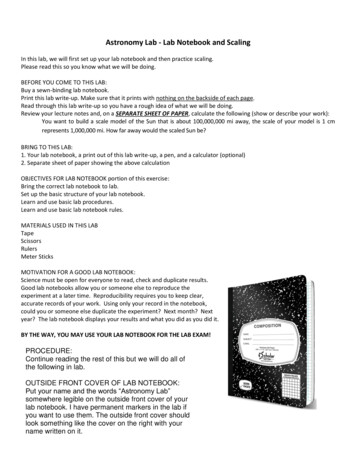
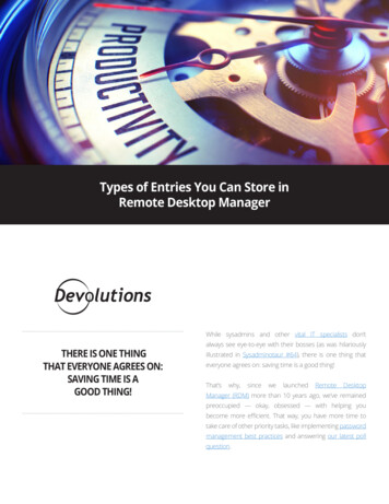
ELEC2501A – Lab 0Part 2: Remote Login into VLSI Lab ComputersOnce you are connected to Carleton’s VPN you can access the lab server and computers. Logging into thesecomputers also gives access to your H: drive, where you should be saving your files. When working on labcomputers, do not save files to locations other than your H: drive. This includes the Desktop, Documents,Downloads, and C: drive. These files not only slow down the computer but will also be periodically deleted.After getting into Carleton’s VPN, you can access the Lab Computers, or Lab Simulation Café Computer usinga remote desktop connection.Local ComputerDesktop From LocalComputerConnect toCarleton VPN.Remote LabComputer ListVLSI Lab ComputerDesktop From the listchoose aRemote DesktopLab Computerfor this lab. Connect to theOscilloscopeThroughBrowser.VLSI SimulationCafé Computer Perform aMultisimsimulation onthe Server.Figure 4: Remote Desktop Hierarchy DiagramTo login to the Remote Access List for the lab computers, reach the website attached and connect to one ofthe computers available. This should open the Remote Desktop Connection application if you are using aWindows computer, or connect to the appropriate equivalent remote desktop application on another operatingsystem*. An example of what the Remote Access List looks like on the website can be seen in Figure 5.Figure 5: Remote Lab Desktop Availability List* The appropriate equivalent for Mac would be Microsoft Remote Desktop applicationOnce you connect to an open computer and open the downloaded Remote Desktop Profile you will be greetedby a window like the one in Figure 6.ELEC 2501 Lab 0Page 4 of 15
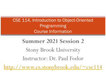
ELEC2501A – Lab 0Figure 6: Windows Remote Desktop Connection ProfileYour computer will not recognize the remote desktop, but you must still Connect.Connecting will lead you to needing to enter your credentials, for Username enter VLSI\{BrightspaceUsername}. For example, if your Brightspace username is ‘johndoe’, the Username would be ‘VLSI\johndoe’.This can be seen in Figure 7 below. You will be prompted for a password. This password is pW{StudentNumber}. So, if your student number is 123456789, then your password is ‘pW123456789’.Figure 7: Expanded Remote Desktop Connection WindowClick OK.This will bring you to the Remote Lab desktop. From here you can access the physical lab components throughapplications, cameras, and other remote desktop connections.Note that the remote desktop connection acts as a window, and can therefore be minimized, resized, andELEC 2501 Lab 0Page 5 of 15
ELEC2501A – Lab 0closed, closing the window will not log you out of the computer, but rather close the remote desktop connection.If closed, your remote access session will end, but it will leave you logged into the computer/server withoutclosing the programs you were using. This can lead to major issues for any users after you, including not beingable to control the equipment. Always Log off your Remote Desktop Connection after closing allapplications to allow other students to access the lab computer. Logging off will also end your remoteaccess session.Figure 8: Lab Computer Remote Desktop ScreenshotELEC 2501 Lab 0Page 6 of 15
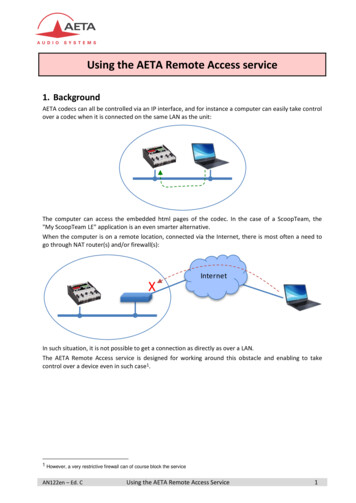
ELEC2501A – Lab 0Part 3: Remote Accessing Rohde & Schwarz RTB2002 OscilloscopeFor many of the labs you will be accessing the oscilloscope and function generator on campus. It will beimportant to familiarize yourself with this process so that you can access the equipment efficiently and in atimely fashion. This equipment can be seen in Figure 9. Before diving in to how to connect to the Rohde &Schwarz RTB2002 oscilloscope, it is important to understand what an oscilloscope is. An oscilloscope is ameasurement device that allows measurement and visualization of AC signals. These devices are verypowerful and commonly used throughout many of your future electronics courses.Figure 9: Rohde & Schwarz RTB2002 And Rigol DG 1022Z as seen through the Camera AppAfter you have successfully connected to Carleton’s VPN and are logged into a lab desktop computer, openthe oscilloscope link found on the desktop. When you open this application, you should be taken to the homepage of the Rohde & Schwarz Oscilloscope as shown in Figure 11. See the Oscilloscope icon below:Figure 10: Oscilloscope LinkELEC 2501 Lab 0Page 7 of 15
ELEC2501A – Lab 0Figure 11: Rohde & Schwarz RTB 2002 Remote Access Home PageOn the left-hand side, click the ‘Remote Front Panel’ link as circled in red.You will be taken to a virtual interface in your web browser that allows you to control the oscilloscope. It will looklike the screenshot shown in Figure 12.Figure 12: Oscilloscope Remote Control Front PanelYou have now successfully accessed the oscilloscope you will be using for the labs in this course. From thispage you will be able to control the buttons and knobs and see the waveform output as if you were sitting in frontof the physical oscilloscope.Lastly, make sure you close your browser window when you are done to allow other classmates a chanceto access the scope. Only one remote user can control a scope at a time. To extend this issue, if you do notclose your browser and do not properly log out of the remote desktop access, future users will not be able toaccess the oscilloscope long after you are done.ELEC 2501 Lab 0Page 8 of 15
ELEC2501A – Lab 0Part 3: Controlling the Rigol DG 1022Z Waveform GeneratorThe Rigol DG1022Z Waveform Function Generator (or function generator) can be used to create many differentAC signals such as sine waves and square waves. In this class the function generator will be used as an ACsignal generator for various circuits. Remote control of the Rigol DG1022Z can be done using the DG1022Z UIexecutable on the desktop. A picture of the app icon can be seen in Figure 13.Figure 13: Rigol Waveform Generator ExecutableOpening the executable will open a window as seen in Figure 14.Figure 14: Rigol Function Generator User Interface WindowThis user interface allows you to control the type of output signal provided (Sine, Square, Ramp, etc), the peakto-peak voltage of the signal (Ampl VPP), the frequency of the signal, and whether the signal is enabled (Output1 is green) and sent to the DG1022 (Through Send). To change the type of signal provided simply select thedesired signal with CH1/CH2. To change the voltage or frequency simply type in the desired value and hit Send.Lastly, to enable the output, click the Output1/2 you want to enable. When highlighted green, the output isenabled for the respective channel.Although you can control the output of the function generator for both channels independently, only Channel 1will be used in this lab. Should you have any issues completing a lab or with controlling a piece of labequipment, contact your lab TAs.ELEC 2501 Lab 0Page 9 of 15
ELEC2501A – Lab 0Part 4: Experimenting with The Function Generator and OscilloscopeThe function generator is currently connected to a simple RC filter. Channel 1 of the oscilloscope is measuringthe waveform being produced by the function generator whereas channel 2 of the oscilloscope is measuring theoutput of the filter.You should be able to view these waveforms as shown in Figure 9. If not, ensure the waveform generator signalis enabled and that you have turned on viewing of each channel on the oscilloscope. You can toggle eachchannel by selecting Ch1 and Ch2 to make them light up or turn off.Scale and Position ChannelsAdjust the signals from channel 1 and channel 2 so that both signals are visible without overlap, take a screenshotof this. Adjust the signals once again so both channels overlap and take another screenshot. You can learn aboutscaling and positioning here.Trigger SettingsExamine the video here. Use the trigger settings to gain a stable signal without shakiness on either channel 1or 2.Experimenting with EquipmentExperiment with the waveform generator by changing the waveform function and observing these changes onthe oscilloscope. Cycle through each of the waveform functions and view their shape on the oscilloscope.Next, adjust the waveform generator to give a sine wave with a 5 V amplitude and frequency of 1 kHz, as shownin Figure 13. Observe the output shown on the oscilloscope. Double the amplitude and frequency on thewaveform generator. Noticing that the oscilloscope is likely not showing the entire waveform anymore adjust thevertical settings to account for this. Do this as well for the horizontal settings to ensure only 2 – 3 periods areshowing.Finally, take a screenshot to upload on Brightspace including both the oscilloscope and the function generatorwindows. To take a screenshot you can use Window’s built in Snipping Tool. This screenshot should show bothwaveforms on the display, proper triggering, and proper scaling and positioning. It should also include yourstudent number as the frequency input for Channel 2 on the waveform generator window.If you are interested in the tools for using an oscilloscope, or other tools in this lab, check out the videos here.ELEC 2501 Lab 0Page 10 of 15
ELEC2501A – Lab 0Part 5: Getting Set Up with NI MultisimSeveral of the laboratories in this course will be completed through the simulation of electric circuits. For thesetasks you will use NI Multisim which is free to available on all ELEC2501 lab computers. You can access theVLSI Simulation Café Computer for Multisim simulations outside of lab times to complete parts of your lab,keep in mind there is never lab equipment attached to the server. During your lab hours you should workon your local machine, outside of your lab hours you should work on the VLSI Simulation CaféComputer.To access NI Multisim, you must first reach the Simulation Café Computer. This can be done by downloadingthe file VLSI Simulation Server.rdp and run it using the Remote Desktop Profile from here while connected tothe Carleton VPN, or by entering the server IP (134.117.38.204) and other information manually through theRemote Desktop Connection Application.To get familiar with the interface and software for future labs, you will set up a simple circuit. When logged inthe simulation server, open Multisim 14.2 from the desktop:Figure 15: NI Multisim IconThis will take you to a blank ‘virtual circuit board’ that allows you the freedom to build and simulate your owncircuits. This will look like the screenshot shown in Figure 17.Figure 16: Multisim Blank WorkspaceThe various toolbars at the top of the window provides what you will need when building and simulating yourcircuits.Start by naming your circuit. Go to File Save as , and save your file to your H: drive in This PC. Name thecircuit what you would like, as an example an appropriate name for this circuit would be‘ELEC2501 Lab0 Practice Circuit’. You should periodically save your work to avoid catastrophes.ELEC 2501 Lab 0Page 11 of 15
ELEC2501A – Lab 0Figure 17: File Navigation MenuBegin building your circuit by adding a voltage source. Click on the ‘Place Source’, or the ground icon on thetoolbar along on the top of the screen and choose ‘AC VOLTAGE’ from the Power Sources Group. Refer toFigure 19. Place the AC Voltage source in your workspace.Figure 18: Sources Selection MenuELEC 2501 Lab 0Page 12 of 15
ELEC2501A – Lab 0Next add a resistor to your circuit. Click on the ‘Place Basic’, or resistor icon on the toolbar and choose one fromthe ‘RESISTOR’ group. Place the resistor in your workspace, and rotate the resistor by selecting it and pressingCTR R.Figure 19: Passive Selection MenuYou should change the component name and values by double clicking on the component and entering in theirnew value and label, do this by entering 22k for 22kΩ for the resistor and for the AC Source change theamplitude and frequency of the source to 1Vrms and 1kHz using the same method. For the resistor, thiscan be seen below:Figure 20: Resistor Editing ScreenshotsUsing the same procedure as with the resistor, add a 0.01µF capacitor to your workspace, along with a groundsource from the Place Source shortcut. Keep in mind, for µ scale, use u in place of 10-6. Next, place wires toconnect the components together. This is done by hovering your mouse over a component node and a crosshairELEC 2501 Lab 0Page 13 of 15
ELEC2501A – Lab 0with a center dot will appear. Clicking on the node, you will begin to lay a wire which you can then use to connectdifferent nodes to one another. An example of this can be seen in Figure 22 below.Figure 21: Adding Wire to Workspace LayoutRepeat this procedure to connect the voltage source in series with the capacitor and resistor. The last componentto add will be the ground reference.The final component to include in this introductory circuit is a measurement probe that allows you to selectwaveforms to observe when running the simulation. To add a voltage probe, navigate the menus Place Probe Voltage, and place the probes according to the image below. These probes are where the simulation willsample voltage from. These voltage probes are referenced to the ground, so it’s important to have a referenceground.Figure 22: Circuit with ProbesELEC 2501 Lab 0Page 14 of 15
ELEC2501A – Lab 0You are now ready to simulate your circuit. The simulation that will be performed is a transient simulation. If yoursettings and sources have not been changed very much, this will mean at time 0, the voltage sources will poweron, and from time 0 to your final time the simulation will try to replicate the circuit on your worksheet.The simulation settings can be changed through the Analyses and simulation menu, which can be reached bynavigating from Simulation Analyses and simulation. Try to reach the Transient option, and enter a start timeof 0s, and a stop time of 5ms.Figure 23: Transient Simulation MenuThe final step is to run your simulation. Click the Run button to observe the time dependent measurement of thevoltage probe. Take a screenshot of the graph result with your student name, and your circuit with yourstudent name using the Snip Tool. You can add your name to the Grapher View window by navigating the menuGraph Add text, placing down the text box and entering your name.After that you have finished lab 0, although with Multisim open, you are able to run various circuits to your heartscontent. Try opening an example circuit from the Multisim Example library by navigating your workspace menuFile Open Samples, and choosing any circuit you might be interested in. Keep in mind, you must save thecircuit to your H: Drive to make any circuit changes permanent.ELEC 2501 Lab 0Page 15 of 15
Figure 7: Expanded Remote Desktop Connection Window Click OK. This will bring you to the Remote Lab desktop. From here you can access the physical lab components through applications, cameras, and other remote desktop connections. Note that the remote desktop connection acts as a window, and can therefore be minimized, resized, and