Transcription
Trident II TritaniumAcetabular System Surgical protocol
Trident II Tritanium surgical protocol2
Trident II Tritanium surgical protocolTrident II Tritaniumsurgical protocolTable of contentsStep 1:Pre-operative planning and X-ray evaluation. 7Step 2:Acetabular preparation. 7Step 3:Reaming. 8Step 4:Window Trial evaluation. 10Step 5:Trident II Shell implantation. 11Step 5A:Optional ancillary screw utilization. 13Step 6:Trial Insert reduction. 15Appendix A: Insert implantation. 16Appendix B: Modular Dual Mobility (MDM)Liner implantation. 18Step 7:Appendix C: Removal of the insert and shell. 19Head disassembly. 20Catalog information. 223
Trident II Tritanium surgical protocolIndications, contraindications & precautionsIndicationsContraindicationsWarnings and precautions Any active or suspected latentinfection in or about the hip joint. Any mental or neuromusculardisorder which would create anunacceptable risk of prosthesisinstability, prosthesis fixationfailure, or complications inpostoperative care.See package insert for warnings,precautions, adverse effects,information for patients and otheressential product information. Painful, disabling joint disease ofthe hip resulting from: degenerativearthritis, rheumatoid arthritis,post-traumatic arthritis or latestage avascular necrosis.Revision of previous unsuccessfulfemoral head replacement, cuparthroplasty or other procedure.Clinical management problemswhere arthrodesis or alternativereconstructive techniques areless likely to achieve satisfactoryresults. Where bone stock is of poorquality or is inadequate for otherreconstructive techniques asindicated by deficiencies of theacetabulum. When used with MDM Liners Treatment of nonunion, femoralneck and trochanteric fracturesof the proximal femur with headinvolvement that are unmanageableusing other techniques. Dislocation risks.Bone stock compromised by disease,infection or prior implantationwhich cannot provide adequatesupport and/or fixation to theprosthesis.Before using Trident II AcetabularSystem instrumentation, verify: Instruments have been properlydisassembled prior to cleaning andsterilization; Instruments have been properlyassembled post-sterilization; Instruments have maintaineddesign integrity; Proper size configurations areavailable.Skeletal immaturity.For Instructions for Cleaning,Sterilization, Inspection andMaintenance of Orthopaedic MedicalDevices, refer to LSTPI-B, QIN 4332,4333, 4382, 4385, 4429, 4430, 4431 andthe following Greatbatch Inc. IFUs:MAN-000020, MAN-000026, MAN0000, D3.3.1.31NT and D3.3.1.16.When used with ConstrainedLiners The Trident Constrained AcetabularInsert is indicated for use inprimary and revision patients athigh risk of hip dislocation dueto a history of prior dislocation,bone loss, joint or soft tissuelaxity, neuromuscular disease, orintraoperative instability.Trident II Acetabular Shells areindicated for cementless use onlyThis publication sets forth detailed recommended procedures for using Stryker Orthopaedics devices and instruments. It offers guidance thatyou should heed, but, as with any such technical guide, each surgeon must consider the particular needs of each patient and make appropriateadjustments when and as required.4
Trident II Tritanium surgical protocolIntroductionThis surgical protocol is a guide topreparing the acetabulum for TridentII Tritanium Shells utilizing TridentII System instrumentation.The Trident II Acetabular System is amodular component design assembledintra-operatively.Trident II Tritanium Shells are a truehemispherical shape and are designedto achieve an interference fit. Theshells are oversized by approximately0.5mm of the labeled size (e.g, 52mmshell 52.5mm in diameter).Shells are available in 2mmincrements ranging from 42mm–66mm in a solidback and clusterholeconfi guration. Multihole shells areavailable in 2mm increments rangingfrom 42mm-72mm.NoteThe Trident Alumina CeramicInserts must exclusively be usedwith Stryker’s Alumina Heads.Refer to Tables 1 and 2 for insert andshell compatibility and sizing options.The Trident II Acetabular Systemuses the Trident Locking Mechanismand is compatible with Trident X3 &Crossfi re polyethylene liners, MDM,Trident Alumina Ceramic lnserts, &Constrained inserts.Refer to the Trident ConstrainedInsert surgical protocol for constrainedinsert use.Table 1: Femoral head, X3 Liner and Shell compatibility chartShell size, liner alpha code, and head size (mm)Solidback &Clusterhole*42444648, 5052, 5456, 5860, 6264, 66Multihole**42444648, 5052, 5456, 5860, 6264, 66Alpha codeAnatomicfemoral .119.621.6*Clusterhole shell sizes 42mm-50mm have 3-holes, and 52mm-66mm have 5-holes.**Multihole shell sizes 42-46mm have 8 holes, 48-50mm have 9 holes, 52-54mm have 11 holes, and 56-72mmhave 13 holes.Trident II Tritanium ShellAlphacodeTrident IITritaniumShellsize (mm)Trident0 , 10 Inserts (mm)TridentEccentric0 , 10 Inserts (mm)TridentElevatedRimInserts (mm)Trident 0 ConstrainedInserts (mm)Trident 10 ConstrainedInserts (mm)A4222, 28**––––B4422, 28**, 32**28*–––C4622, 28, 32**2828––D48, 5022, 28, 32, 36**28, 322822–E52, 5422, 28, 32, 36, 40**28, 32, 3628, 32, 362222F56, 5822, 28, 32, 36, 40**, 44**28, 32, 3628, 32, 362822G60, 6222, 28, 32, 36, 40**, 44**28, 32, 3628, 32, 362828H64, 6622, 28, 32, 36, 40**, 44**28, 32, 3628, 32, 363228I68, 7022, 28, 32, 36, 40**, 44**28, 32, 3628, 32, 363228J7222, 28, 32, 36, 40**, 44**28, 32, 3628, 32, 363228*Available in 0 only** Available in X3 only and 0 only5
Trident II Tritanium surgical protocolTable 2: MDM Liner and insert compatibility with Trident II ShellsShell size (mm), liner alpha codeTrident II Tritanium Shell4648, 5052, 5456, 5860, 6264, 6668, 7072Alpha codeCDEFGHIJ36C38D42E46F48G52H54I58JPoly Insert OD (mm)3638424648525458Poly Insert ID (mm)22.222.2282828282828Nominal poly thickness (mm)6.77.76.88.89.811.812.814.8MDM CoCr LinerTrident II TritaniumSolidbackTrident II TritaniumClusterhole ShellTrident II TritaniumMultiholeMDM CoCr LinerX3 Polyethylene InsertTridentConstrained InsertAlumina CeramicFemoral HeadLFIT CoCrFemoral HeadBIOLOX deltaCeramic HeadAluminaCeramic Liner6
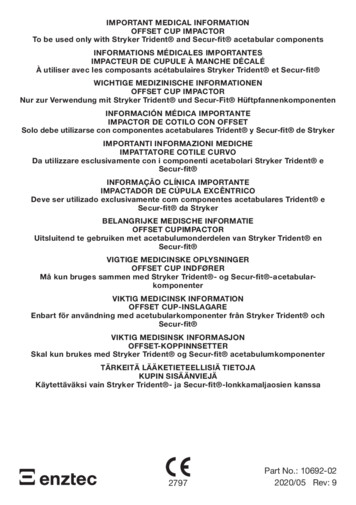
Trident II Tritanium surgical protocolStep 1Pre-operativeplanning andX-ray evaluationPre-operative planning and X-rayevaluation aid in the selection of theappropriate implant style and size forthe patient’s anatomy and hip pathology.Selecting potential implant styles andsizes can facilitate operating roompreparation and assure availabilityof an appropriate size implant. X-rayevaluation may also help detectanatomic anomalies that could preventthe intra-operative achievement of theestablished pre-operative goals.Step 2AcetabularpreparationThe acetabulum is prepared by using thesurgeon’s preferred technique to gainadequate exposure for reaming. Excisionof the labrum and osteophytes allowsfor proper visualization of the bonyanatomy and improves ease of reaming.Stryker’s femoral and wing retractors canbe utilized to gain acetabular exposure.(Figure 1)With the acetabulum exposed, bonydefects can be identified. If necessary,bone grafting options may be consideredprior to reaming.NoteCareful identification and removal ofosteophytes can help reduce thepossibility of bone-to-bone orcomponent-to-bone impingement.Figure 1.7
Trident II Tritanium surgical protocolStep 3ReamingHandles are available in straight and offset configurations toconnect to CuttingEdge Reamers (Figures 2a, 2b, 3). It isrecommended to begin reaming at least 4mm smaller than thetemplate size after removing medial osteophyte. Progressivereaming should proceed in 1mm to 2mm increments until thefinal size is achieved.The surgeon should consider acetabular bone quality whenpreparing for an interference fit with the acetabular shell.Trident II Tritanium Shells are oversized by approximately0.5mm of the labeled size (e.g, 52mm shell 52.5mm indiameter). The recommended technique for Trident IITritanium Shells is to ream line-to-line with the planned shellsize, however, a surgeon may choose to make intra-operativeadjustments based on the patient’s bone quality (for example, inpatients with osteoporotic bone, under-reaming by 1mm of thelabeled size may be considered). Start rotating the reamer priorto engaging bone to reduce initial torque upon contact.The profile of the reamer necessitates reaming to the fulldepth. The reamer should be driven to the point where the rimcontacts the acetabular wall at the peripheral lunate region.If bone stock allows, reaming should optimize bone contactagainst both the posterior and anterior walls.Care should be taken to prevent enlarging or distorting theprepared cavity by eccentric reaming. Ideally, final reamingprovides mechanical support for the acetabular shell directlyon viable host bone.Many surgeons prefer to target a zone of 40 10 of inclination and 15 10 of anteversiondepending on patient anatomy and biomechanicsNotes Changes in pelvic tilt and pelvic flexion caused by patient positioning on the table, as well as disease in thecontralateral hip, spine and pelvis, may impact a surgeon’s ability to attain the desired component placementfrom pre-operative planning. The amount of interference fit should be determined intra-operatively based upon the patient’s bone qualityand acetabular size. When osteoporotic bone is encountered, it is recommended to under-ream by 1mm of thelabeled shell size. When sclerotic bone is encountered, it may be difficult to fully seat the shell. In thissituation, it is recommended to ream line-to-line to reduce the potential for problems that may typically occurin dense bone.Potential challenges when implanting acetabular shells may include: acetabular fracture, incomplete seatingof the implant in the prepared cavity, or slight deformation of the titanium shell making the insert moredifficult to seat. Following reaming, the surgeon should ensure that soft tissues are clear and osteophytes are removed from theprepared site. The reamers perform best when sharp. Care should be taken to protect the reamer from unnecessary handling,as dull or damaged cutting teeth may cause improper reaming. Dull cutting teeth may deflect to cut softer boneand resist hard bone. This situation may result in an irregularly shaped or enlarged acetabular preparation.8
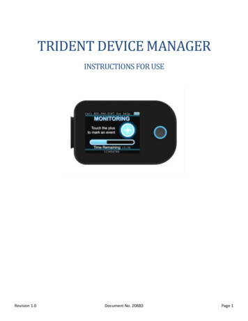
Trident II Tritanium surgical protocolFigure 2a.Straight Reamer Handle (2102-0410)Figure 2b.Offset Reamer Handle (T6320)Figure 3. (2102-04xx) CuttingEdge reamer basketCuttingEdge Reamer Handle instructionsFigure 4.Figure 5.The reamer is attached to the reamer handle bypushing down and applying a quarter-turn tolock in place.Removal of the reamer from the handle is performedby pulling back on the locking sleeve and rotating thereamer head a quarter-turn in a clockwise direction.9
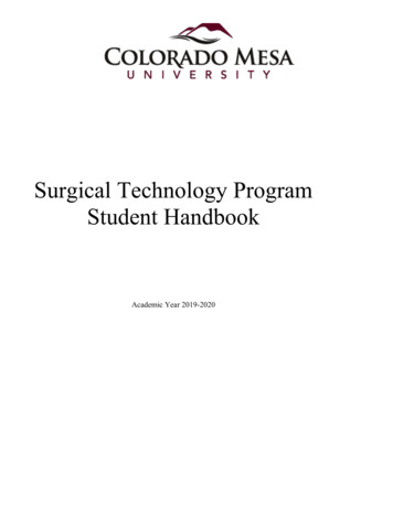
Trident II Tritanium surgical protocolStep 4Window trial evaluationSelect a Window Trial of equal diameter or 1mm smaller than the last acetabular reamer used. Attach the Window Trialonto the Shell Impactor to evaluate the fit within the reamed acetabulum (Figure 6). The trial is windowed forvisualization and assessment of depth, position, bone contact and congruency within the acetabulum. Impact gently intothe acetabulum to avoid damage to the surrounding bone or press-fit.Figure 6.InstructionsWindow TrialTo attach, insert the tip of the impactor flush with thesquare recess in the dome of the trial. Turn the knob clockwise until the trial is attached. For the straight impactor, itmay be required to apply light pressure on the knob inthe direction of the trial to initially engage the threads.Failure to completely thread the components together mayresult in damage to the threads upon impaction and lead todifficulty in detaching the components. Do not overtighten.NoteIt is recommended to use a Window Trial that isline-to-line or 1mm smaller than the last reamer.10
Trident II Tritanium surgical protocolStep 5Shell implantationInstrument instructionsAssess the acetabular bone and surrounding soft tissue toensure shell insertion will not be inhibited. Prior toimplantation, it is prudent to re-assess patient positioning inthe surgical field and adjust to the correct position if necessary.Shell impactorsInsert the impactor tip flush with the square recess in the shelldome (Figure 7). Turn the knob clockwise while applying aslight pressure towards the shell until it is attached. For theStraight Shell Impactor, it may be required to apply light pressure on the knob in the direction of the shell to initially engagethe threads.Select the appropriately sized Trident II Tritanium Shell asidentified on the product label. Attach the shell to theimpactor using the instructions in the table.An Alignment Guide can be attached to the Shell Impactor toaid in establishing abduction/inclination and anteversionangles (Figure 9). Many surgeons prefer to target a zone of40 10 of abduction and 15 10 of anteversion depending onpatient anatomy and biomechanics. The shell abduction angleof approximately 45 is determined by positioning theAlignment Guide perpendicular to the long axis of the patient(Figure 10). Shell anteversion is set at approximately 20 bymoving the Shell Impactor so that the left/right anteversionrod is parallel to the long axis of the patient (Figure 11).The screw hole pattern in the shell is intended to beoriented superiorly for ancillary screw fixation. Duringshell insertion, avoid damage to the roughened surface frominstruments such as retractors, and avoid dragging across softtissue to keep the shell free of debris.Impact the shell into the acetabulum using a mallet until astable press-fit is achieved. Remove the impactor by carefullyunthreading from the shell. The shell seating depth may bedetermined by viewing the acetabulum through the exposeddome hole. Should further seating be required, the impactorcan be reattached to the shell to facilitate secondary impaction.Figure 7.Failure to completely thread the components together may resultin damage to the threads upon impaction. Do not overtighten. Thegap on the knob indicates an inadequate connection and will beconcealed after appropriate tightening (Figure 8).Figure 8.An optional Hex Dome Hole Plug may only be inserted intothe shell using the Trident II Straight Driver (7005-0099) oroptional U-Joint Driver (7005-0100). Only these two drivershave a captive tip design to hold the Dome Hole Plug on,however excessive shaking or motion may cause the plug todetach. Evaluate the plug after insertion to confi rm it is fullythreaded into the shell to prevent impingement with the liner.AlignmentguidesFigure 9.Lateral 1440-1370orSupine 1440-1380To attach, slide theAlignment Guide ontothe flats of the impactorspindle and rotate it tothe desired location.Straight Shell Impactor: 7004-010011
Trident II Tritanium surgical protocolFigure 10.45 90 A/P viewFigure 11.20 Lateral viewNotes Avoid catching soft tissue debris onto the frictional shell surface during implantation. Shell positioning must be carefully considered when selecting certain inserts as hooded options are notavailable in all sizes to adjust joint stability. Proper positioning of the Trident II Acetabular Shell mayminimize potential impingement and promote stability and articulation between the insert and head.As with any acetabular system, excessive vertical orientation and/or anteversion of the shell should beavoided as this may lead to premature wear and/or noise of the components’ surfaces. While the alignment guides offer some assistance in shell placement, it is important to critically evaluateanatomic landmarks before shell implantation. These anatomic landmarks include the anterior and posteriorwalls of the acetabulum, the sciatic notch, the trans-acetabular ligament (TAL), the floor and/or acetabularfossa of the acetabulum.CautionThe alignment guide may yield inaccurate placement if the pelvis has moved from the original position duringintra-operative manipulation. Small changes in pelvic flexion will greatly affect anteversion. The alignmentguide is only one aid to assist with proper implant positioning. The surgeon must also rely on anatomiclandmarks to avoid improper positioning of components.12
Trident II Tritanium surgical protocolStep 5AOptional ancillary screw fixationIf the decision is made to use ancillary screw fi xation, then only 6.5mm Low Profile Hex Screws (7030-65XX) may be used.The cancellous bone screws are 6.5mm in diameter and available in a variety of lengths from 15-60mm (Table 3).The acetabular screws are designed to be inserted and removed with the Trident II screw instrumentation (Table 4).Single Use Drill Bits are also offered for bone preparation.Attach a 3.3 or 4.0mm Drill Bit to the Ball Joint Drill Shaft and connect to an appropriate power bone drill. After determiningthe site for screw placement, pass the appropriately sized Drill Bit through the Drill Guide of equivalent diameter size andinsert the guide flush to the shell screw hole (Figure 12). Use of the guide ensures proper alignment of the hole trajectory tothe screw hole and facilitates full seating of the screw head within the shell upon insertion. Drill to the desired depth andinsert the Depth Gauge to aid in selection of the appropriate screw size.To insert a screw using the Trident II Non-Captive U-Joint Driver (marked “Non-Captive”) (Figure 13), use the screw forcepsto hold the screw and guide into the implant.If using the Trident II Straight Driver, attach the screw to the driver tip. The straight driver tip has a captive design to hold thescrew on, however excessive shaking or motion may cause the screw to detach. Screw forceps may be used to hold the screwand guide into the implant.Following screw insertion into bone, confi rm the screw head is seated flush against the shell to prevent eventual improperseating of the acetabular insert.Table 3.Notes6.5mm Low Profile Hex Screws An optional Trident II U-Joint Driver with a captivetip (7005-0100) is available as an alternative to theTrident II Non-Captive U-Joint Driver. To use thisdriver, attach the screw to the driver tip. The tiphas a captive design to hold the screw on, howeverexcessive shaking or motion may cause the screw todetach. Screw forceps may be used for this mm7030-655055mm7030-655560mm7030-6560Figure 12. Trident II Acetabular Shells are not intended to bedrilled through. In dense bone, the use of 4.0mm Drill Bits mayfacilitate easier insertion of screws withoutsubstantial compromise of screw purchase. For drilling screw holes deeper than 40mm, it isrecommended to drill sequentially with a 25mm/40mm bit and then follow with a 60mm bit todeepen to desired depth.Caution Do not use a dull drill bit as it may generateexcessive stresses in the bone. Do not pass a drill, screw any other instrumentationbeyond the inner table of the pelvis.Drill GuideDrill BitMalposition of either the shell screw holeorientation or bone hole trajectory, or improper useof the screws may result in injury to theneurovascular structures in the vicinity. Once screws are inserted, confi rm screw heads donot protrude into the inside of shell and interferewith proper assembly of liner implant. Do not use a power drill to insert the screw asexcessive torque may result in damage to screw ordriver.Figure 13. Operating the Ball Joint Drill Shaft at anglesexceeding 45 for prolonged periods of time or withexcessive force can lead to damage to the flexiblejoint and drill bit.13
Trident II Tritanium surgical protocolScrew instrument instructionsBall Joint Drill ShaftTo attach, retract the sleeve and insert the bit so that thelasermarking on the bit is concealed within the shaft tip.Ratchet HandleTo attached driver, retract the sleeve and insert the driver sothat engraved line on the shaft is concealed within the sleeve.Figure 14.Figure 15.10mmDrill Bit lengthThe Drill Guide conceals 10mm of the Drill Bit length (Figure 16) example of 40mm Drill Bit).Depth GaugeLocate the end of the bone hole using the hook on the tip of thegauge. Clamp onto the gauge at the level of the screw hole andextract the gauge to use the markings to aid in appropriate screwsize selection.40mmFigure 16.Table 4.Trident II screw instrumentsCatalog no.Single-use instrumentsDescriptionCatalog no.DescriptionSingle Use Drill Bit 3.3mm x 15mmRatchet Driver Handle7005-01017005-3315SNon-Captive U-Joint Driver7005-01027005-3325SSingle Use Drill Bit 3.3mm x 25mmU-Joint Driver7005-01007005-3340SSingle Use Drill Bit 3.3mm x 40mmStraight Driver7005-00997005-3360SSingle Use Drill Bit 3.3mm x 60mmScrew Forceps7005-05007005-4015SSingle Use Drill Bit 4.0mm x 15mmDepth Gauge - Short7005-02007005-4025SSingle Use Drill Bit 4.0mm x 25mmDepth Gauge - Long7005-02017005-4040SSingle Use Drill Bit 4.0mm x 40mmBall Joint Drill Shaft7005-03007005-4060SSingle Use Drill Bit 4.0mm x 60mmDrill Guide 3.3mm7005-0433Drill Guide 4.0mm7005-0440Drill Bit 3.3mm X 25mm7005-3325Drill Bit 3.3mm X 40mm7005-3340Drill Bit 3.3mm X 60mm7005-3360Drill Bit 4.0mm X 25mm7005-4025Drill Bit 4.0mm X 40mm7005-4040Drill Bit 4.0mm X 60mm7005-406014
Trident II Tritanium surgical protocolStep 6Trial Insert reductionp 0º (2200-XXX) only A joint mechanics evaluation may be performed with implanttrials following femoral preparation and shell implantation.Insert a Trial Insert into the Trident II Shell (Figure 17a).An optional Trial Insert Hex Containment Screw for securingthe trial to the shell is available (Figure 17b). Only use aStraight Driver (7005-0099) or optional Trident II U-Joint(7005-0100) to insert the Hex Containment Screw. Only thesetwo drivers have a captive tip design to hold the HexContainment Screw on, however excessive shaking or motionmay cause the screw to detach.Do not overtighten as this may lead to liner trial damage.To facilitate insertion/removal of the Trial Insert, ScrewForceps may be placed into the two holes in the plastic face.After reducing the femoral and acetabular trials, the patientshould be taken through a complete range of motion. Trialsmatching the fi nal selected implant sizes should be used.Careful assessment of impingement at the extreme range ofmotion should be performed. A fi nal check of hip mechanicsshould be completed to include range of motion consistentwith the patient’s normal daily activities. 0º (2200-XXX) & 10º (2210-XXX) 0º (2200-XXX),10º (2210-XXX)& Elevated rim (2260-XXX)Alphacode22mm28mmA pB ppC pD pE p32mm36mm40mm44mmF ppG ppH ppI ppJ ppTrident eccentric trialsp 0º (2240-XXX) only 0º (2240-XXX) & 10º (2250-XXX)Alpha code28mmBpC D E F At this point joint laxity should also be assessed, taking intoconsideration the type of anesthetic used and its effects onsoft tissue. Additionally, an intra-operative X-ray may betaken at this point to assess leg length, offset, component sizeand position.NoteImpingement should be carefully assessed and avoidedduring range of motion. Impingement can result inincreased wear in metal-polyethylene systems, as wellas instability.32mm36mmG H I J RetainingRingHexScrewTrial Insert Hex Containment Screw Kit 7003-0000Figure 17a.Figure 17b.15
Trident II Tritanium surgical protocolAppendix AInsert implantationThe Trident Polyethylene Insert locks into the shell by meansof a circumferential ring that engages the mating groovewithin the shell. Rotational stability can be achieved whenthe anti-rotational barbs of the shell interlock with the insertscallops. Trident Alumina Ceramic Inserts gain fi xationwithin the shell by means of mating tapers. Rotationalstability between the components is achieved when the shell’santi-rotational barbs interlock with the insert scallops.NoteHaving a clear view of the rim of the acetabulum will alloweasier visualization of the shell slots and indexing barbs forproper positioning and seating of the liner.NoteUse caution handling ceramic components during assemblybecause of brittle nature of the ceramic material. Allcomponents are pre-sterilized and cannot be sterilizedafter opening.1. Ensure that the inside of the shell and periphery are cleanand free of soft tissue or any other debris which can causeeccentric positioning of the insert and improper seating inthe shell.2. Gently introduce the ceramic or polyethylene insertmaking sure that the insert flange scallops are alignedwith the slots at the rim of the shell. This orientation willallow the insert to rest on the four indexing barbs andwill ensure that the insert is parallel with the shell. Oncethe insert is seated at the initial position, slowly turn anddrop the insert into the final prelocked position.3. Select the appropriately sized Plastic Insert Impactor Tip andload onto Insert Positioner/Impactor Handle (Figure 18).4. Position Insert Positioner/Impactor Handle into innerdiameter of insert. Take care to align handle with the axisof shell. Strike handle with approximately four fi rm malletblows to fully seat the insert (Figure 19).Figure 19.Figure 18.16
Trident II Tritanium surgical protocolAppendix A (continued)Head assemblyPrior to head assembly to the implanted femoral stem, necklength selection may be re-evaluated using Stryker’s V40 orC-Taper head trial. Place the head trial onto the stem necktaper and reduce the hip to verify that the mechanics have notbeen altered due to shell seating.Remove the head trial and dry the implant trunnion with alaparatomy sponge or sterile towel.Select the appropriate corresponding V40 or C-Taper femoralhead size and place it onto the dry trunnion of the femoral stemwith a slight twist. Impact the head with moderate impactions inline with the neck using the Stem Head Impactor (1104-1000)(Figure 20). Care should be taken to prevent scratching of thefemoral head against the acetabular component rim during finalreduction.With the final selected femoral, head, and acetabular implantsin place, reduce the components and perform a final jointmechanics evaluation of the patient.Figure 20.Optional stepUniversal Adaptor SleevesPart numbersTaperStem materialcompatibility19-0XXXTC-TaperTMZF, Ti-6Al-4V, CoCr6519-T-XXXV40TMZF, Ti-6Al-4V,CoCr, Stainless SteelAfter completing the trialing process, assemble the UniversalAdapter Sleeve to the femoral stem manually. The UniversalAdapter Sleeve must be fully seated on the stem taper beforethe head is assembled. Intra-operatively assemble the BIOLOXdelta Universal Taper Ceramic Head onto the sleeved femoralstem and set with moderate impactions in line with the neckusing the Stem Head Impactor (1104-1000). Care must be takento avoid excessive impact forces when assembling the BIOLOXdelta Ceramic Head to the sleeved femoral component.Notes When selecting a BIOLOX delta Universal TaperCeramic Head for implantation, use of a UniversalAdapter Sleeve is necessary. In no instance should any attempt be made topreassemble the Universal Adapter Sleeve inside theBIOLOX delta Universal Ceramic Head.17
Trident II Tritanium surgical protocolAppendix BModular Dual MobilityNotesMDM Liner implantationEnsure that the inside of the shell is clean, dry and free ofsoft tissue or any other debris, which could prevent the linerfrom properly seating in the shell. As with any modular interface under load, there is apotential for fretting and/or corrosion. Properalignment and locking of the MDM Liner into theshell may help to minimize this risk.Gently introduce the MDM Liner making sure that the linerflange scallops are aligned with the slots in the rim of theshell. This orientation will allow the liner to rest on the fourindexing barbs and will ensure that the liner is parallelwith the shell. Next, slowly turn the liner until it drops intothe final pre-locking position. Correct rotational orientationwill result in the liner tabs aligned with the slots on theshell rim.Apply finger pressure around the rim of the liner first toengage the liner within the shell.Load a 36mm Plastic Insert Impactor Tip onto the InsertPositioner/Impactor Handle. It may be necessary to lightlytap on the rim of the liner with the Plastic Insert ImpactorTip, working around the rim in all four quadrants, to ensurethe liner is properly seated and concentric within the shell.The liner is properly seated when there is no further rockingor movement of the liner within the shell. This step shouldbe done prior to final impaction of the liner.Position the Postioner/Impactor handle into the innerdiameter of the liner. Take care to align the handle with theaxis of the shell. Strike the handle with several mallet blowsto fully seat the liner. MDM Liners lock within the shell bymeans of mating tapers.Verify the liner is properly aligned and fully seated into theacetabular shell. Check the taper lock by running a smallblunt instrument (or the Liner Removal Tool) around theperiphery of the shell/ liner interface. There should not beany space between the rim of the shell and the underside ofthe rim.Visually assess the inner articular surface of the MDM Linerto ensure it is not scratched or damaged prior to the trialinsert/head reduction.18 Having a clear view of the rimof the acetabulum will allow easier visualizati
For Instructions for Cleaning, Sterilization, Inspection and Maintenance of Orthopaedic Medical 4333, 4382, 4385, 4429, 4430, 4431 and the following Greatbatch Inc. IFUs: MAN-000020, MAN-000026, MAN- 0000, D3.3.1.31NT and D3.3.1.16. This publication sets forth detailed recommended procedures for using Stryker Orthopaedics devices and instruments.