Transcription
Practical Yield Line DesignAn introduction to the practical use of Yield Line Theory in the design ofeconomic reinforced concrete slabs, including examples of design of flatslabs, raft foundations and refurbishmentG. Kennedy MSc (Eng), CEng MICEC. H. Goodchild BSc, CEng, MCIOB, MIStructE
AcknowledgementsGerard Kennedy would like to acknowledge Trevor Powell, co-founder of Powell Tolner and Associates,for the encouragement and support given to him over the years in the application of Y.L.D.Charles Goodchild would like to acknowledge that this publication would not have been possiblewithout the enthusiasm and drive of Gerard Kennedy and other partners, notably John Sestak andstaff at Powell Tolner and Associates, and for their tenacity in insisting that the commercialpotential of Yield Line Design should be recognised and shared.We would both like to thank the many individuals who contributed to this publication; amongst them:Stuart AlexanderK BaskaranSharon HartTony JonesJohn MorrisonBob PoveyCam MiddletonDr Chris MorleyMartin SouthcottAlan ToveyGillian BondIssy HarveyPublished by The Concrete CentreRiverside House, 4 Meadows Business Park, Station Approach, Blackwater, Camberley, Surrey GU17 9ABTel: 44 (0)1276 606800 Fax: 44 (0)1276 606801TCC/03/3Published September 2004ISBN 1-904818-08-0Price Group L. The Concrete CentreThis publication was first made available on the website of the Reinforced Concrete Council.The RCC has now devolved and transferred to The Concrete Centre.All advice or information from The Concrete Centre is intended for those who will evaluate the significance and limitations ofits contents and take responsibility for its use and application. No liability (including that for negligence) for any loss resultingfrom such advise or information is accepted by The Concrete Centre or their subcontractors, suppliers or advisors. Readersshould note that The Concrete Centre publications are subject to revision from time to time and should therefore ensurethat they are in possession of the latest version.
Practical Yield Line DesignContentsNotation . . 1.02Introduction1.1 The essentials . . . .1.2 Frequently asked questions . . . 382.0The Work Method of analysis2.1 General . . . 222.2 The Work Method . 232.3 Orthotropic slabs . 383.0Standard formulae for slabs3.1 One-way spanning slabs . .3.2 Two-way spanning slabs .3.3 Two-way slabs - supports on 4 sides . . . .3.4 Two-way slabs - supports on 3 sides . . . .3.5 Two-way slabs - supports on 2 adjacent sides . . .3.6 Flat slabs (on a rectangular grid of columns) . . .456466748488How to tackle . . . . .4.1 Flat slabs: general . . . .4.2 Flat slabs supported by rectangular grids of columns . . .4.3 Flat slabs on irregular grids of columns . . . 4.4 Slabs with beams . 4.5 Transfer slabs . . 4.6 Raft foundations . . . . 4.7 Refurbishments . 93981201271351361434.05.0Case studies6.0Summary . . 155 . 1487.0References and further reading7.1 References. . . . 1567.2 Further reading. . . . 158Appendix . . . 1601
Practical Yield Line DesignNotationSymbolsThe symbols used in this publication have the following meaning:SymbolDescriptionUnitsAArea of column cross-sectionm2a, b, cPlan dimensions of slab supported on several sidesmDDissipation of internal energykNmEExpenditure of energy by external loadskNmgUltimate distributed dead loadkN/m2gkCharacteristic distributed dead loadkN/m2H1, H2 Holding down reaction at slab cornerkNh1, h2 Yield line pattern defining dimensionmi, i1, i2 .Ratio of negative support moment to positive midspan moment,i.e i1 m1’/mlLength of a yield line (projected onto a region’s axis of rotation)mLSpan (commonly edge to edge), distance,mmPositive moment, i.e the ultimate moment along the yield line(bottom fibres of slab in tension).kNm/mm’, m1’,m2’Negative moment, i.e the ultimate moment along the yield line(top fibres of slab in tension).kNm/mmrUltimate moment of resistance (based on the steel provided)kNm/mnUltimate distributed load p gkN/m2pUltimate distributed live loadkN/m2pa, pbUltimate line loadkN/mpkCharacteristic distributed live loadkN/m2q 1 , q2 Ultimate support reactionkN/mSUltimate column reaction from slab tributary areakNs1, s2Distance to point of contraflexure from supportmx1, x2Distance to section of max. positive moment from supportm δmaxDeflection, maximum deflection (usually taken as unity)mθAngle of rotationm/mAdjusted ultimate distributed load (adjusted for light line loadsthrough factors α and β).kN/m2Reduced sides dimensionsmnhar, brDrawing notationThe convention used in drawings and sketches is given belowSupportsFree edgeContinuous supportSimple supportColumn supportYield linesmPositive (sagging) yield line,kNm/mAxis of rotationm’Plastic hinge (in sectionalelevation or in plan)Negative (hogging) yield line,kNm/mLoadsLine load, kN/mP 2Point load, kN Centre of gravity of load kN
1.0 Introduction1.0 IntroductionThis publicationThe aim of this publication is to (re-) introduce practical designers to the use of Yield LineDesign. The intention is to give an overall appreciation of the method and comprehensivedesign guidance on its application to the design of some common structural elements. Itassumes that the user has sufficient experience to recognise possible failure patterns andsituations where further investigation is required.The basic principles of Yield Line theory are explained and its application as a versatilemethod for the design and assessment of reinforced concrete slabs is demonstrated. Theoryis followed by practical examples and the accompanying commentary gives insights into theyears of experience brought to bear by the main author, Gerard Kennedy.The publication is intended as a designer’s aid and not an academic paper. It commits topaper a practical approach to the use of Yield Line for the design of concrete slabs. Itgives guidance on how to tackle less simple problems, such as the design of flat slabs,rafts, refurbishment and slab-beam systems. Whilst the publication covers the design ofcommon elements, it is an introduction, not a comprehensive handbook: in moreexacting circumstances, designers are advised to consult more specialistliterature. The examples are practical ones that may be followed, but should not beextended too far without reference to more specialist literature.Yield Line Theory challenges designers to use judgement and not to rely solely on computeranalysis and design. Once grasped, Yield Line Theory is exceedingly easy to put intopractice and everyone in the procurement chain benefits. Simple design leads to simpledetails that are fast to detail and fast to fix. Current initiatives such as Egan [4] andpartnering, etc, should challenge designers to revisit and re-evaluate the technique.1.1 The essentials1.1.1 What is Yield Line Design?Yield Line Design is a well-founded method of designing reinforced concrete slabs, andsimilar types of elements. It uses Yield Line Theory to investigate failure mechanisms atthe ultimate limit state. The theory is based on the principle that:work done in yield lines rotating work done in loads movingTwo of the most popular methods of application are the ‘Work Method’ and the use ofstandard formulae. This publication explains these two methods and illustrates how theymay be used in the practical and economic design of reinforced concrete slabs such as flatslabs, raft foundations and refurbishments1.1.2 What are the advantages of Yield Line Design?Yield Line Design has the advantages of: Economy Simplicity and VersatilityYield Line Design leads to slabs that are quick and easy to design, and are quick and easyto construct. There is no need to resort to computer for analysis or design. The resultingslabs are thin and have very low amounts of reinforcement in very regular arrangements.The reinforcement is therefore easy to detail and easy to fix and the slabs are very quickto construct. Above all, Yield Line Design generates very economic concrete slabs,because it considers features at the ultimate limit state.3
Practical Yield Line DesignYield Line Design is a robust and proven design technique. It is a versatile tool thatchallenges designers to use judgement. Once grasped Yield Line Design is an exceedinglypowerful design tool.1.1.3 What is the catch?Yield Line Design demands familiarity with failure patterns, i.e. knowledge of how slabsmight fail. This calls for a certain amount of experience, engineering judgement andconfidence, none of which is easily gained. This publication is aimed at ‘experienced’ engineers,who will recognise potential failure patterns. At the same time it is hoped that the publicationwill impart experience to younger engineers and encourage them to appreciate modes offailure and this powerful method of design.Yield Line Design tends to be a hand method. This may be seen as both an advantage anddisadvantage. Each slab has to be judged on its merits and individually assessed. The methodallows complex slabs to be looked at in a simple way, and, in an age of computers, it gives anindependent method of analysis and verification. This is especially important for those who arebecoming disillusioned with the reliance placed on Finite Element Analysis. They see a need toimpart greater understanding and remind designers that reinforced concrete does notnecessarily behave in an elastic manner. Nonetheless it is hoped that the option of suitable andaccessible software for Yield Line Design will become available in the near future.Yield Line Design concerns itself with the ultimate limit state. It does not purport to deal withserviceability issues such as deflection per se. Nonetheless, deflection can be dealt with bysimple formulae based on the yield moment. This publication shows how compliance withspan-to-depth criteria may be achieved.Column moments cannot be derived directly. They must be derived using separate elastic subframe analyses as is the case when using continuous beam analysis (assuming knife edgesupport), or by analysing separate yield line failure patterns discussed in section 4.17.In the past Yield Line Design has been disadvantaged by half-truths and misrepresentations.Taking reasoned and pragmatic measures to overcome them easily dispels theoreticalproblems such as ‘upper bound theory therefore unsafe’. These measures are discussed in thispublication. This is perhaps the first time this practical approach has been set down in writing advocates of Yield Line Design have been designing in this way for years.1.1.4 Economy and simplicityIn slabs, Yield Line Design gives least weight reinforcement solutions coupled with leastcomplication. These points were illustrated on the in-situ building of the European ConcreteBuilding Project at Cardington [1] where, uniquely, many different methods of design andTable 1.1 Configurations of flexural reinforcement in the in-situ building at Cardington [1]FloornoFlexural reinforcement/floor*Bar marks/floor1Traditional loose bar - Elastic Design16.9752Traditional loose bar - Elastic Design17.1763Rationalised loose bar - Elastic Design15.3**544Blanket cover loose bar - ½ Yield Line design14.5*2223.2*33- ½ Elastic Design4Tonnes5One-way mats - Elastic Design19.9426Blanket cover two-way mats - FE Design25.5207Not part of the particular research project*Values given are for a whole floor.**1.6T additional reinforcement would have been required to meet normal deflection criteria
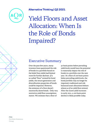
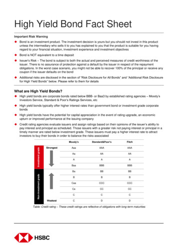
1.1 The essentialsdetailing were carried out, constructed and compared. Yield Line Design was used on the 4thfloor and required the least amount of reinforcement as shown in Table 1.1. This shows thatfor a complete floor, 14.5 tonnes of reinforcement would have been used using Yield LineTheory compared to 16.9 tonnes using more conventional elastic design methods.The Yield Line Design at Cardington also led to very few bar marks being required: onlythe heavy blanket cover solution required fewer.The economy of Yield Line Design is further illustrated in Figure 1.1, which shows the 4thfloor at Cardington [1] during construction. The steel fixers are laying out the T12@200 B(565 mm2/m) reinforcement for the yield line half of the slab adjacent to the T16 @ 175 B(1148 mm2/m) in the elastically designed half towards the top of the picture. Each half ofthe slab performed well.Figure 1.1 European Concrete Building Project at Cardington - 4th floor duringconstructionThe half in the foreground was designed using Yield Line Design. The otherelastically designed half was intended to be ‘highly rationalised’. However,the number of bar marks used in the Yield Line Design was less than eventhe most rationalised of the Elastic Designs. It is worth noting that thedeflections measured on the two halves under the same load were virtuallyidentical.With Yield Line Theory the designer is in full control of how the moments are distributedthroughout the slab. This leads to the opportunity to use simple reinforcement layouts –regular spacing of bars and fewer bar marks – that are easier for the designer, detailer,contractor and fixer. These arrangements are far more regular than with other methods ofanalysis such as Elastic or Finite Element Analysis.These bar arrangements are premeditated and lead to the following advantages: For the detailer, regular layouts mean minimum numbers of bar marks. Often stocklengths can be specified. Drawings are quicker to produce, easier to detail and easier to read on site. Regular arrangements of reinforcement mean quicker fixing. The principles of simple reinforcement layouts are well suited to prefabrication ofsteel into welded mats and also to contractor detailing There is less chance of errors occurring Checking is easier.5
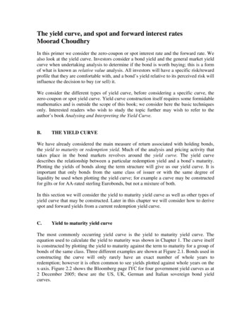
Practical Yield Line Design1.1.5 The opportunityThe management consultants who undertook research at Cardington [1] concluded:“Yield Line Design appears to provide a great opportunity for more competitive concretebuilding structures .”1.1.6 VersatilityOnce understood, Yield Line Design is quick and easy to apply. It may be used on alltypes of slab and loading configurations that would otherwise be very difficult to analysewithout sophisticated computer programmes. It can deal with openings, holes, irregularshapes and with any support configuration. The slabs may be solid, voided, ribbed orcoffered, and supported on beams, columns or walls.The following are typical areas of application: An irregularly supported flat slab as shown in Figure 1.2, may, as illustrated byFigure 1.3 (and Section 4.3), be analysed by considering yield line patterns in theform of folded plates or worst-case quadrilaterals.Figure 1.2 An irregular flat slab .Figure 1.3 .may be analysed using Yield Line Design – by considering quadrilaterals 6Yield Line Theory can be used very effectively in refurbishment work. It is used inthe assessment of existing slabs and can be especially useful where the supportsystem is amended and/or new holes have to be incorporated. (New holes are dealtwith by adjusting the length of postulated Yield Lines.) Yield Line Theory can be
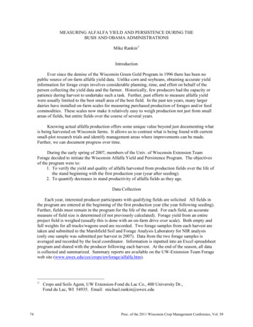
1.1 The essentialsused to estimate the ultimate load capacity of such slabs and so optimise and/orminimise structural works on site. The theory can be used to analyse slabs with beams: composite T and L beams maybe incorporated into a combined collapse mechanism. Yield Line Theory is usedeffectively in the design and assessment of slabs in bridges. Yield Line Theory can also be applied to slabs resting on soil, i.e. industrialground floor slabs, foundation rafts etc. The piled raft foundation illustrated inFigure 1.4 was analysed and designed using Yield Line Theory - simply and by hand(see Example 4F).REGIONCREGIONPattern 2bPattern 2aREGIONBDPattern 2cREGIONAFigure 1.4 A piled raft – easily dealt with using Yield Line Theory and Design7
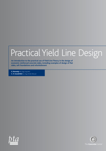
Practical Yield Line Design1.2 Frequently asked questionsYield Line Design is easy to grasp but there are several fundamental principles that needto be understood. Yield Line Design is a plastic method: it is different from ‘normal’ elasticmethods, and to help with the transition in the thought processes, definitions,explanations, main rules, limitations, etc have been gathered together here in this section1.2.1 What is a yield line?A yield line is a crack in a reinforced concrete slab across which the reinforcing bars haveyielded and along which plastic rotation occurs.1.2.2 What is Yield Line Theory?Yield Line Theory is an ultimate load analysis. It establishes either the moments in anelement (e.g. a loaded slab) at the point of failure or the load at which an element willfail. It may be applied to many types of slab, both with and without beams.Consider the case of a square slab simply supported on four sides as illustrated by Figure1.5. This slab is subjected to a uniformly distributed load, which gradually increases untilcollapse occurs.Initially, at service load, the response of the slab is elastic with the maximum steel stressand deflection occurring at the centre of the slab. At this stage, it is possible that somehairline cracking will occur on the soffit where the flexural tensile capacity of the concretehas been exceeded at midspan.Increasing the load hastens the formation of these hairline cracks, Increasing the loadfurther will increase the size of the cracks further and induce yielding of thereinforcement, initiating the formation of large cracks emanating from the point ofmaximum deflection.On increasing the load yet further, these cracks migrate to the free edges of the slab atwhich time all the tensile reinforcement passing through a yield line yields.Square slab simply supportedHair cracksLarge cracks emanatingfrom point of maximumdeflectionCracks shown are on slab soffitFigure 1.5 Onset of yielding of bottom reinforcement at point of maximum deflectionin a simply supported two-way slab8
1.2 Frequently asked questionsAt this ultimate limit state, the slab fails. As illustrated by Figure 1.6, the slab is dividedinto rigid plane regions A, B, C and D. Yield lines form the boundaries between the rigidregions, and these regions, in effect, rotate about the yield lines. The regions also pivotabout their axes of rotation, which usually lie along lines of support, causing supportedloads to move. It is at this juncture that the work dissipated by the hinges in the yieldlines rotating is equated to work expended by loads on the regions moving. This is YieldLine Theory.Axes of rotation alongsupports to rigidregions A,B,C & DADBYield lines formingyield line patternCFor a more detailed appraisal of thesituation at corners see Section 1.2.11Figure 1.6 The formation of a mechanism in a simply supported two-way slab with thebottom steel having yielded along the yield linesUnder this theory, elastic deformations are ignored; all the deformations are assumed tobe concentrated in the yield lines and, for convenience, the maximum deformation isgiven the value of unity.1.2.3 What is a yield line pattern?When a slab is loaded to failure, yield lines form in the most highly stressed areas andthese develop into continuous plastic hinges. As described above, these plastic hingesdevelop into a mechanism forming a yield line pattern.Yield lines divide the slab up into individual regions, which pivot about their axes ofrotation. Yield lines and axes of rotation conform to rules given in Table 1.2, which helpwith the identification of valid patterns and the Yield Line solution.Table 1.2 Rules for yield line patterns Axes of rotation generally lie along lines of support and pass alongside anycolumns. Yield lines are straight. Yield lines between adjacent rigid regions must pass through the point ofintersection of the axes of rotation of those regions. Yield lines must end at a slab boundary. Continuous supports repel and simple supports attract positive or sagging yieldlines.9
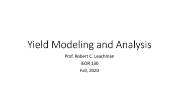
Practical Yield Line Design1.2.4 What is a Yield Line solution?In theory, there may be several possible valid yield line patterns that could apply to aparticular configuration of a slab and loading. However, there is one yield line pattern thatgives the highest moments or least load at failure. This is known as the yield line solution.The designer has several ways of determining the critical pattern and ensuring safedesign: From first principles, e.g. by using The Work Method Using formulae for standard situations.It will be noted that valid yield line patterns give results that are either correct ortheoretically unsafe. These ‘upper bound solutions’ can deter some designers but, asdiscussed later, this theoretical awkwardness is easily overcome by testing differentpatterns and by making suitable allowances (see 10% rule later).1.2.5 How do you select relevant yield line patterns?A yield line pattern is derived mainly from the position of the axes of rotation, (i.e. thelines of support) and by ensuring that the yield lines themselves are straight, go throughthe intersection of axes of rotation and end at the slab boundary, i.e. conform to the rulesin Table 1.2. Some simple examples are shown in Figure 1.7. Considering a slab to be apiece of pastry laid over supports may help designers to visualise appropriate yield linepatterns.The aim of investigating yield line patterns is to find the one pattern that gives the criticalmoment (the highest moment or the least load capacity). However, an exhaustive searchis rarely necessary and selecting a few simple and obvious patterns is generally sufficientas their solutions are within a few percent of the perfectly correct solution. Section 2.1.12illustrates that absolute dimensional accuracy is unnecessary for engineering purposes.ColumnAxes ofrotationFigure 1.7 Simple Yield Line patterns1.2.6 What is a fan mechanism?Slabs subjected to heavy concentrated loads may fail by a so-called fan mechanism, withpositive Yield Lines radiating from the load and a negative circular Yield Line centredunder the point load. This mechanism is shown in Figure 1.8. It is rare for this form offailure to be critical but nonetheless a check is advised where large concentrated loads arepresent or for instance in flat slabs where the slab is supported on columns.10
1.2 Frequently asked questionsm'm positive (sagging) moment, kNm/mm’ negative (hogging) moment, kNm/mmPoint loadrFigure 1.8 Fan collapse pattern for a heavy concentrated load onto a reinforced slabThe mechanism for a slab supported by a column is the same shape butwith the positive and negative yield lines reversed.1.2.7 What is the Work Method?The Work Method (or virtual Work Method) of analysis is the most popular (and mosteasy) way of applying Yield Line theory from first principles. Indeed, many experiencedusers of Yield Line theory of design choose to use the Work method because it is so veryeasy. The fundamental principle is that work done internally and externally must balance.In other words, at failure, the expenditure of external energy induced by the load on theslab must be equal to the internal energy dissipated within the yield lines. In other words:External energyexpended by loads moving Internal energydissipated by rotations about yield linesExpended DissipatedE DΣ (Ν x δ) for all regions Σ (m x l x θ) for all regionswhereN load(s) acting within a particular region [kN]δ the vertical displacement of the load(s) N on each region expressed as afraction of unity [m]m the moment in or moment of resistance of the slab per metre run [kNm/m]l the length of yield line or its projected length onto the axis of rotation for thatregion [m]θ the rotation of the region about its axis of rotation [m/m]By way of illustration, consider the slab shown in Figure 1.6. Figure 1.9 shows anaxonometric view of this two-way simply supported slab that has failed due to a uniformlydistributed load. Note that: The triangular regions A, B, C and D have all rotated about their lines of support. The loads on the regions have moved vertically and rotation has taken place aboutthe yield lines and supports. The uniformly distributed load on each of these regions will have moved on average1/3 of the maximum deflection.The rotation of the regions about the yield lines can be resolved into rotation about theprincipal axes of rotation, and thereby measured with respect to the location and size ofthe maximum deflection.11
Practical Yield Line DesignRotation θΑRotation θΒADBCPoint of maximumdeflection atcentre of slabPoint of maximum deflectionat centre of slabFigure 1.9 Deformed shape at failureThis, fundamentally, is the ‘Work Method’. Any slab can be analysed by using the principleof E D. Some judgement is required to visualise and check likely failure patterns butabsolute accuracy is rarely necessary and allowances are made to cover inaccuracies.Once a yield line pattern has been selected for investigation, it is only necessary to specifythe deflection as being unity at one point (the point of maximum deflection) from whichall other deflections and rotations can be found.The Work Method is covered in more detail in Chapter 2.1.2.8 FormulaeRather than go through the Work Method, some practitioners prefer the even quickermethod of using standard formulae for standard types of slab. The formulae arepredominantly based on the work method and they are presented in more detail inChapter 3.As an example, the formula for one-way spanning slabs supporting uniformly distributedloads is as follows [2,6]:m 2(nL21 i1 1 i2)2per unit widthwherem ultimate sagging moment along the yield line [kNm/m]m’ ultimate support moment along the yield line [kNm/m]n ultimate load [kN/m2]L span [m]i 1 , i2 ratios of support moments to mid-span moments. (The values of i are chosenby the designer: i1 m’1/m, i2 m’2/m)Where slabs are continuous, the designer has the freedom to choose the ratio of hoggingto sagging moments to suit any particular situation. For instance, the designer maychoose to make the bottom span steel equal to the top support steel (i.e. make saggingmoment capacity equal support moment capacity.)Failure patterns for one-way spanning slabs are easily visualised and the standardformulae enable the designer to quickly determine the span moment based on any ratio ofhogging moments he or she chooses to stipulate (within a sensible range dictated bycodes of practice). Formulae are also available for the curtailment of top reinforcement.12
1.2 Frequently asked questionsFormulae for two-way spanning slabs supported on two, three or four sides are alsoavailable for use. These are a little more complicated due to the two-way nature of theproblem and the fact that slabs do not always have the same reinforcement in bothdirections. The nature of the failure patterns is relatively easy to visualise and again thedesigner has the freedom to choose fixity ratios.The formulae are presented and discussed in Chapter 3.1.2.9 Is Yield Line Theory allowable under design codes of practice?Yes.Any design process is governed by the recommendations of a specific code of practice. Inthe UK, BS 8110 [7] clause 3.5.2.1 says ‘Alternatively, Johansen’s Yield Line method .may be used . for solid slabs’. The proviso is that to provide against serviceabilityrequirements, the ratio of support and span moments should be similar to those obtainedby elastic theory. This sub-clause is referred to in clauses 3.6.2 and 3.7.1.2 making theapproach also acceptable for ribbed slabs and flat slabs.According to Eurocode 2 [3], Yield Line Design is a perfectly valid method of design.Section 5.6 of Eurocode 2 states that plastic methods of analysis shall only be used tocheck the ultimate limit state. Ductility is critical and sufficient rotation capacity may beassumed provided x/d 0.25 for C50/60.A Eurocode 2 goes on to say that the methodmay be extended to flat slabs, ribbed, hollow or waffle slabs and that corner tie downforces and torsion at free edges need to be accounted for.Section 5.11.1.1 of EC2 includes Yield Line as a valid method of analysis for flat slabs. It isrecommended that a variety of possible mechanisms are examined and the ratios of themoments at support to the moment in the spans should lie between 0.5 and 2.1.2.10 Yield Line is an upper bound theoryYield line theory gives upper bound solutions - results that are either correct ortheoretically unsafe, see Table 1.3. However, once the possible failure patterns that canform have been recognised, it is difficult to get the yield line analysis critically wrongTable 1.3 Upper and lower bound ultimate load theoriesUltimate load theories for slabs fall into two categories: upper bound (unsafe or correct) orlower bound (safe or correct).Plastic analysis is either based on upper bound (kinematic) methods, or onlower bound (static) methods.Upper bound (kinematic) methods include: plastic or yield hinges method for beams, frames and one-way slabs;Yield Line Theory for slabs.Lower bound (static) methods include: the strip method for slabs,the strut and tie approach for deep beams, corbels, anchorages, walls andplates loaded in their plane.AThis relates to an ultimate moment, M, 110 kNm in
l Length of a yield line (projected onto a region's axis of rotation) m L Span (commonly edge to edge), distance, m m Positive moment, i.e the ultimate moment along the yield line (bottom fibres of slab in tension). kNm/m m', m 1', m 2' Negative moment, i.e the ultimate moment along the yield line (top fibres of slab in tension).