Transcription
Enviro-Septic & Simple-Septic LeachingSystems Design and Installation ManualMaine State Attachment
Enviro-Septic & Simple-Septic Leaching Systems Designand Installation ManualMaine State AttachmentPurposeThe purpose of this attachment is to provide information specific to the State ofMaine for use in the design and installation of septic leaching systems usingthe Presby Environmental, Inc., group of products.CertificationrequiredThe State of Maine requires all designers and installers of Multi-Level systems to be certified. Certification is obtained by attending the “EnviroSeptic Designer and Installer Certification Course” presented by PresbyEnvironmental, Inc.PresbyEnvironmental,Inc., standardsAll leaching systems using Presby Environmental, Inc., products must bedesigned and installed in compliance with the procedures and specificationsdescribed in The Enviro-Septic & Simple-Septic Leaching Systems Designand Installation Manual.This attachment is to be used in conjunction with the Maine Subsurface WasteWater Disposal Rules and other State or local regulations regarding septicsystems.State standardstake precedentWhile the Presby Environmental, Inc., standards form the basis for designingand installing Enviro-Septic products, the information in this State attachmenttakes precedence in the event of conflicts.In thisattachmentThis attachment contains State specific information on the following subjects.SubjectDesign flowHigh flowLoading limitsLow flowRaised systems fill requirementsSand fill and clean fill requirementsTrench systems spacingMaine Single Level Quick Reference GuideMaine Multi-Level Quick Reference GuideSlope Design ChartTechnicalsupportPage22222223611Presby Environmental, Inc., provides technical support to all individuals usingour products. For questions about our products or the information contained inthis manual, please contact us at 1-800-473-5298.1
State Specific InformationDesign flowDesign flow is defined in Chapter 5 of the Maine Subsurface WasteWater Disposal Rules.High flowHigh flow is a volume greater than design flow of 900 GPD.Loading limitsEach line of a distribution box system and each section of acombination system has a maximum limit design flow of 500 GPD.Low flowLow flow is a volume design flow of 900 GPD or less.Raised systemsfill extensionsRaised, level, or sloping systems which slope 10% or less require 3’extensions on each side (including system sand and sand fill) beforetapering.Sloping systems which slope greater than 10% must require 3’extensions on three sides and 5’ on the down slope side before tapering.Tapering is to be 4:1 (maximum 2:1 with variance).A dense soil blanket is required around the fill perimeter of raisedsystems.Sand fill andclean fillrequirementsSand fillWith the exception of the 6” of system sand surrounding the EnviroSeptic pipe, sand fill is defined in the Maine Subsurface Waste WaterDisposal Rules, Section 804.2Clean fill (Backfill)Clean fill is defined as clean, permeable fill material.Trench systemspacingTrench systems require a minimum of 4’ center-to-center spacing.2
MaineSingle Level Quick Reference GuidePurposeThe unique Enviro-Septic design provides an infinite number of systemconfigurations that vary in length, width, slope, and shape. The purpose of thisguide is to help designers compare layouts for any site quickly and easily.We recommend designers become familiar with the “Enviro-Septic Design &Installation Manual” before using this Quick Reference Guide.ReductionsReductions in the linear footages used in this quick reference guide require arequire variance variance.Distancesadhere to StaterulesThe minimum separation distances and setbacks used in this guide (includingthe vertical separation distance to the seasonal ground water table or restrictivehorizon) adhere to The Maine Subsurface Waste Water Disposal Rules and aremeasured from the nearest outer edge of Enviro-Septic pipe.Note: If Enviro-Septic pipe is installed below original grade, (in-ground) theminimum separation distance to the seasonal ground water table orrestrictive horizon shall be increased by 6”.ProcedureComplete these tasks to size a single level Enviro-Septic leaching system.Task 1: Determine the linear feet of Enviro-Septic pipe required.Use the soil profile and the number of bedrooms or the commercial GPD inTable A below to determine the linear feet of Enviro-Septic pipe required.Table A: Linear ber of Bedrooms456 Add'l mercialPer 100 GPD82666652Example: A three-bedroom home with a soil profile of 5requires 140 feet of pipe.Note: Each bedroom has a design flow of 90 GPD.Continued3
Single Level Quick Reference Guide, ContinuedTask 2: Determine the percentage of slope on the proposed system.Note: The maximum slope for a single level system is 25%. Maine requires a variancefor system slopes over 20%. The site slope may be greater if fill is used to keepthe system slope within the maximum.Do you know the percentage of slope on the proposed system?If yes, go to Task 3.If no, follow this procedure to determine the percentage of system slope.Step123456ActionIdentify the highest elevation of the proposed location.Identify the lowest elevation of the proposed location.Subtract the lowest elevation from the highest elevation elevation change.Measure the horizontal distance between the two elevations horizontallength.Divide the elevation change by the horizontal length percentage of site slope.Choose a percentage of slope to be used for the system.7Note: The system slope does not need to be the same as the site slope.Go to Task 3.Task 3: Determine the minimum center-to-center pipe spacing.Use the soil profile and the percentage of system slope in Table B below to determinethe required minimum center-to-center pipe spacing.Table B: Pipe SpacingPercentage ofSystem Slope5&64Soil : A slope of ten percent or less with a soil profile of 5requires pipe spacing of 1.5’.Continued4
Single Level Quick Reference Guide, ContinuedTask 4: Determine system length and width.IF.system length ismost criticalTHEN use Table C below to.find the system length in the left columnfollow that row across to a number equal to or greater than therequired linear feet of Enviro-Septic follow that column down through the number of lines row and acrossleft to the required center-to-center spacing. find the pipe spacing in the bottom left hand column and follow thatrow across to the desired width follow that column up through the number of lines row and up to therequired linear feet of Enviro-Septic follow that row left to determine the system length. system width ismost criticalTable C: Length and 95100# of 754.004.254.504.755.00Linear Feet of Enviro-Septic 067.5071.00System Width/Ft (Outermost surface of pipe)5
MaineMulti-Level Quick Reference GuidePurposeThe purpose of this guide is to help designers determine system layouts for anysite quickly and easily. We recommend designers become familiar with the“Enviro-Septic Design & Installation Manual” before using this QuickReference Guide.RestrictionSimple-Septic pipe may not be used in Multi-Level systems.Distancesadhere to StaterulesThe minimum separation distances and setbacks used in this guide (includingthe vertical separation distance to the seasonal ground water table or restrictivehorizon) adhere to The Maine Subsurface Waste Water Disposal Rules and aremeasured from the nearest outer edge of Enviro-Septic pipe.Note: If Enviro-Septic pipe is installed below original grade, (in-ground) theminimum separation distance to the seasonal ground water table orrestrictive horizon shall be increased by 6”.VariancesrequiredMulti-Level systems are currently approved for two levels. Systems overtwo levels require variances.Exceptions to any Maine Subsurface Waste Water Disposal Rules used in thisquick reference guide require variances.ProcedureComplete these tasks.Task 1: Determine the linear feet of Enviro-Septic pipe required.Use the soil profile and the number of bedrooms or the commercial GPD inTable A below to determine the linear feet of Enviro-Septic pipe required.Table A: Linear FootageSoilProfile2452131103103Non-Commercial and ResidentialNumber of Bedrooms3456 Add'l 1915819823840CommercialPer 100 GPD73575744Example: A six-bedroom home with a soil profile of 6requires 238 feet of pipe.Note: Each bedroom has a design flow of 90 GPD.Continued6
Multi-Level Quick Reference Guide, ContinuedContinue these tasks.Procedure(continued)Task 2: Determine the percentage of slope on the proposed system.Note: The maximum slope for a Multi-Level system is 25%. Maine requires avariance for system slopes over 20%. The site slope may be greater if fill isused to keep the system slope within the maximum.Do you know the percentage of slope on the proposed system?If yes, go to Task 3.If no, follow this procedure to determine the percentage of system slope.Step123456ActionIdentify the highest elevation of the proposed location.Identify the lowest elevation of the proposed location.Subtract the lowest elevation from the highest elevation elevation change.Measure the horizontal distance between the two elevations horizontallength.Divide the elevation change by the horizontal length percentage of site slope.Choose a percentage of slope to be used for the system.7Note: The system slope does not need to be the same as the site slope.Go to Task 3.Task 3: Determine the minimum center-to-center pipe spacing.Use the soil profile and the percentage of system slope in Table B below to determinethe required minimum center-to-center pipe spacing.Table B: Pipe SpacingPercentage ofSystem Slope6Soil .5’2.75’Example: A slope of ten percent or less witha soil profile of 6 requires pipespacing of 1.5’.Continued7
Multi-Level Quick Reference Guide, ContinuedTask 4: Determine system length and width.IF.system length is mostcriticalsystem width is mostcriticalTHEN use Table C below to. find the system length in the left column follow that row across to a number equal to or greater than the requiredlinear feet of Enviro-Septic follow that column down through the number of lines row and across left tothe required center-to-center spacing. find the pipe spacing in the bottom left hand column and follow that rowacross to the desired width follow that column up through the number of lines row and up to therequired linear feet of Enviro-Septic follow that row left to determine the system length.Center-to-center pipe spacing in feetLength of lines in feetTable C: Multi-Level Length and 6.0080100120100 125150120 150180140 175210160 200240180 225270200 250300220 275330240 300360260 325390280 350420300 375450320 400480340 425510360 450540380 475570400 5006004563.25 4.004.753.63 4.505.384.00 5.006.004.38 5.506.634.75 6.007.255.13 6.507.885.50 7.008.505.88 7.509.136.25 8.009.756.63 8.50 10.387.00 9.00 11.007.38 9.50 11.637.75 10.00 12.258.13 10.50 12.888.50 11.00 85093590099095010451000 110010117.758.508.889.7510.00 11.0011.13 12.2512.25 13.5013.38 14.7514.50 16.0015.63 17.2516.75 18.5017.88 19.7519.00 21.0020.13 22.2521.25 23.5022.38 24.7523.50 820.2521.6323.0024.3825.7527.1328.50System Width/Ft (Outermost surface of pipe)Table continues on next .2536.00
Length of lines in ble continues on next page.Center-to-center pipe spacing in 6.5050.0053.5057.0060.5064.0067.5071.009System Width/Ft (Outermost surface of 2.5035.1337.7540.3843.0045.6348.2550.8853.50Table C: Multi-Level Length and 50
Length of lines in feetCenter-to-center pipe spacing in 7586.5091.2596.0010System Width/Ft (Outermost surface of 445464730.25 31.00 31.75 32.50 33.25 34.00 34.75 35.5035.13 36.00 36.88 37.75 38.63 39.50 40.38 41.2540.00 41.00 42.00 43.00 44.00 45.00 46.00 47.0044.88 46.00 47.13 48.25 49.38 50.50 51.63 52.7549.75 51.00 52.25 53.50 54.75 56.00 57.25 58.5054.63 56.00 57.38 58.75 60.13 61.50 62.88 64.2559.50 61.00 62.50 64.00 65.50 67.00 68.50 70.0064.38 66.00 67.63 69.25 70.88 72.50 74.13 75.7569.25 71.00 72.75 74.50 76.25 78.00 79.75 81.5074.13 76.00 77.88 79.75 81.63 83.50 85.38 87.2579.00 81.00 83.00 85.00 87.00 89.00 91.00 93.0083.88 86.00 88.13 90.25 92.38 94.50 96.63 98.7588.75 91.00 93.25 95.50 97.75 100.00 102.25 104.5093.63 96.00 98.38 100.75 103.13 105.50 107.88 110.2598.50 101.00 103.50 106.00 108.50 111.00 113.50 116.00Table C: Multi-Level Length and 874.5080.6386.7592.8899.00105.13111.25117.38123.50
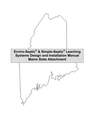
PIPE SPACING CENTER-TO-CENTERPIPE SPACING CENTER-TO-CENTER9/16 0.0451/24.50'4.25'3/83/85/16 0.0285/16 0.0251/41/43/16 0.0183/16 0.0153.25'3.00'2.75'2.50'2.25'2.00'1.75'1.50'4 3/163 3/42.50'2.25'2 1/24 5/82.75'1.50'5 1/163.00'3 3/85 7/163.25'2 15/165 7/83.50'1.75'6 5/163.75'2.00'6 3/44.00'7 9/164.50'7 1/884.75'4.25'8 00.0337/16 0.0353.50'0.0401/27/16 0.0384.00'3.75'0.0439/16 0.0500.0550.0600.0650.0700.0750.0800.0858 1/82 11/163 1/83 5/84 1/164 1/24 15/165 3/85 3/46 5/166 3/47 3/167 5630.6000.6380.6750.7130.75015%8 9/1693/87/161/29/165/811/163/43/413/167/815/1611 1/16 0.0901 1/81 3/16 750.0833 3/83 13/164 5/164 13/165 1/45 3/46 1/46 3/47 3/167 11/168 3/168 5/89 1500.1600.1700.1800.1900.2007/81 1/161 3/161 3/81 1/21 5/81 13/161 15/162 1/82 1/42 3/82 9/162 11/162 00.4400.4800.5200.5600.6000.6400.6800.7200.7601 1/161 1/41 7/161 5/81 13/1622 3/162 5/162 1/22 11/162 7/83 1/163 1/43 7/163 2250.2400.2550.2700.2850.3001 1/41 1/21 11/161 7/82 1/82 5/162 1/22 3/42 15/163 1/83 3/83 9/163 3/444 .2630.2800.2980.3150.3330.3507%4 9/161 7/161 11/161 15/162 3/162 3/82 5/82 7/83 1/83 3/83 5/83 13/164 1/164 .3000.3200.3400.3600.3800.4008%4 13/16SYSTEM SLOPE6%1 5/81 7/82 3/162 7/162 11/1633 1/43 1/23 3/44 1/164 .3380.3600.3830.4050.4280.4509%4 9/164 7/85 1/85 .6380.6800.7230.7650.8083 3/44 5/164 7/85 3/85 15/166 1/277 9/168 1/88 5/89 3/169 3/410 1/411 6750.7200.7650.81044 9/165 1/85 11/166 1/46 13/167 7/1688 9/169 1/89 11/1610 1/41211 3/81.0000.9501212 5/80.7130.3330.3800.4280.4750.5230.5700.6180.6654 3/164 13/165 3/866 5/87 3/167 13/168 3/899 5/80.7500.3500.4000.4500.5000.5500.6000.6500.7009 7/165 1/165 11/166 5/166 15/167 9/168 3/168 13/160.7880.4200.4730.5250.5780.6300.6830.7359 7/85 1/45 15/166 5/87 1/47 15/168 9/169 1/41114 80.3850.4130.4400.4681.093 13 11/16 1.14022 5/162 5/833 5/163 5/83 15/164 5/164 5/84 15/165 1/45 5/80.4950.5230.55011%5 15/166 1/46 5/80.93511 3/40.9780.8250.4400.4950.5500.6050.6600.7150.77010 3/85 1/26 3/166 7/87 9/168 1/499 11/160.9601.0200.4600.5180.5750.6330.6900.7485 3/46 1/27 3/167 15/168 5/89 3/80.4800.5400.6000.6600.7200.7800.805 10 1/16 0.8400.863 10 13/16 0.90011 1/212 1/40.990 12 7/16 1.035 12 15/16 1.08013 1/80.800 10 1/16 0.840 10 9/16 0.880 11 1/16 0.92011 1/411 7/80.998 12 9/16 1.0450.808 10 3/16 0.850 10 11/16 0.8930.76022%1.050 13 3/16 1.100 13 13/16 1.15021%0.855 10 13/16 0.900 11 5/16 0.9450.855 10 13/16 0.90320%DIFFERENCE IN ELEVATION BETWEEN LINES OF ENVIRO-SEPTIC PIPE IN FEET (Fractions and Decimals)3 9/164 1/164 9/165 1/85 5/86 1/86 5/87 1/87 5/88 3/168 11/169 3/169 3500.3750.4000.4250.4500.47523%1 13/162 1/82 3/82 11/1633 5/163 5/83 7/84 3/164 1/24 13/165 1/85 3/80.50010%5 11/166DIFFERENCE IN ELEVATION BETWEEN LINES OF ENVIRO-SEPTIC PIPE IN FEET (Fractions and Decimals)3/413/1615/161 1/161 3/161 5/161 7/161 9/161 11/161 13/161 15/162 1/162 3/162 1/42 3/84%0.800 10 3/16 0.850 10 13/16 0.90016%9 5/89/165/83/413/167/811 1/16 0.0901 3/16 0.0981 1/41 3/81 7/16 0.1201 1/21 5/81 11/16 0.1431 13/16 0.1503%SLOPE DESIGN CHART6 13/1666 3/47 1/28 1/499 3/410 1/211 1/41212 3/413 1/214 0.8130.8750.9381.0001.0631.1251.1881.25025%2 3/162 1/22 7/83 1/43 5/83 15/164 5/164 11/165 1/165 3/85 3/46 1/86 1/20.60012%7 3/1613%2 5/162 3/43 1/83 1/23 7/84 5/164 11/165 1/165 7/165 7/86 1/46 5/877 7/167 13/16
Notes
Notes
The information in this attachment is subject to change without notice. Your suggestions andcomments are welcome. Please contact us atPresby Environmental, Inc.Route 117, PO Box 617Sugar Hill, NH 03585Phone: 1-800-473-5298 Fax: (603) 823-8114Website: www.presbyenvironmental.comEnviro-Septic U.S. Patent Nos. 6,461,078; 5,954,451; 6,290,429 with other patents pending. Canadian Patent Nos.2185087; 2187126 with other patents pending. Simple-Septic U.S. Patent No. 5,606,786. Presby Maze U.S. PatentNo. 5,429,752.Enviro-Septic , Simple-Septic , and Presby Maze are registered trademarks of Presby Environmental Inc. MultiLevelTM , is a trademark of Presby Environmental, Inc. 2003 Presby Environmental, Inc. All rights reserved. Publication date: April 2003.
All leaching systems using Presby Environmental, Inc., products must be designed and installed in compliance with the procedures and specifications described in The Enviro-Septic & Simple-Septic Leaching Systems Design and Installation Manual. This attachment is to be used in conjunction with the Maine Subsurface Waste