Transcription
The information in this manual is subject to change without notice. We make a continual effort to improveour Manuals in order to ensure they are as complete, accurate and helpful as possible. Please confirmthat this is the most recent and up-to-date version of this Manual by contacting us at (800) 473-5298 orvisiting our website, www.presbyenvironmental.comYour questions, suggestions and comments are welcome. Please contact us at:Presby Environmental, Inc.143 Airport RoadWhitefield, NH 03598Phone: 1-800-473-5298 Fax: (603) 837-9864Website: www.PresbyEnvironmental.comJan. 2013 MSMIMPORTANT NOTICE: This Manual is intended ONLY for use in designing and installingPresby Environmental’s Advanced Enviro-Septic Wastewater Treatment System.The use of this Manual with any other product is prohibited.The processes and design criteria contained herein are based solely onour experience with and testing of Advanced Enviro-Septic .Substitution of any other large diameter gravelless pipe will result in compromised treatment ofwastewater and other adverse effects.This Manual sets forth the Manufacturer’s recommendations and requirements;designers and installers are responsible for determining and complying with applicablestate and/or local regulations.Advanced Enviro-Septic U.S. Patent Nos. 6,461,078; 5,954,451; 5,606,786; 6,899,359;6,792,977 and 7,270,532 with other patents pending.Canadian Patent Nos. 2,300,535; 2,185,087; 2,187,126 with other patents pending.Multi-Level Advanced Enviro-Septic U.S. Patent No. 6,290,429 with other patents pending.Enviro-Septic is a registered trademark of Presby Environmental Inc.Advanced Enviro-Septic is a registered trademark of Presby Environmental, Inc.
Table of ContentsPagesSection A, Introduction1-4Section B, Components5-7Section C, System Sizing, AES Pipe Requirements & Design Example8-9Section D, System Configurations10-15Section E, Design Criteria for Virginia16-21Section F, Pumped System Requirements22Section G, Venting Requirements23-26Section H, Site Selection27Section I, System Sand & Fill Material Specifications28Section J, Preparing for Installation29-30Section K, Installation & Construction Procedures31-33Section L, Final Grading34-35Section M, Operation & Maintenance36Section N, Rejuvenation & Expansion of AES Systems37Section O, Sampling Device Installation & Use38-42Extra Details 1, Unique Site Solutions for any Soil Type43Extra Details 2, Unique Site Solutions for Distribution of Effluent afterSecondary or Advanced Treatment Presby Environmental, Jan. 2013. All Rights Reserved44-45
Advanced Enviro-Septic Treatment SystemVirginia Design and Installation ManualSection A, IntroductionWhat isAdvancedEnviroSeptic ?Advanced Enviro-Septic (“AES”) is an innovative onsite wastewater treatmentsystem that is passive, non-mechanical and does not use pressure distribution. Theprimary component is a large diameter perforated, multi-layer fabric-wrapped pipethat is installed in a bed of specified System Sand. The Advanced Enviro-Septic System is designed to purify wastewater that has received primary treatment in aseptic tank and to disperse the treated wastewater into the underlying soils. Thesystem is extremely versatile and can be designed in a variety of shapes and sizes,making it adaptable to virtually any residential or commercial application. Theamount of pipe required and the size of the System Sand bed adjust in relation to theamount of daily design flow, the soil’s characteristics and site constraints, ensuringeffective treatment and adequate absorption into underlying soils.How DoesAdvancedEnviro-Septic work?By utilizing simple yet effective natural processes, the Advanced Enviro-Septic Treatment System treats septic tank effluent in a manner that prevents suspendedsolids from sealing the underlying soil, increases system aeration, and provides agreater bacterial area (“biomat”) than conventional septic systems.Why isAdvancedEnviro-Septic Better?The Advanced Enviro-Septic Treatment System retains solids in its pipe andprovides multiple bacterial surfaces to treat effluent prior to its release into the soil.The continual cycling of effluent (the rising and falling of liquid inside the pipe)enhances bacterial activity. No other passive wastewater treatment system designoffers this functionality. Our systems excel because they are more efficient, lastlonger, and have a minimal environmental impact.SystemAdvantages Provides superior treatmentThoroughly tested to prove it worksPreserves the natural terrainCost-effective to construct and operateCompletely passive, requires no mechanical devices or electricityDesign versatility to adapt to virtually any site, any flow, any applicationQuicker and easier to installEnhanced function and longevityRequires no special maintenanceSuperior track record of reliabilityMade using recycled plastic1
Introduction, continuedPurposeThe purpose of this Manual is to provide general information regarding the designcriteria, installation procedures and use and care instructions for the AdvancedEnviro-Septic Treatment System.The Advanced Enviro-Septic System is extremely versatile and, as a result, thisManual cannot possibly set forth every conceivable system configuration. Weencourage you to contact our Technical Advisors, who will be happy to address anyquestions or concerns unique to your project or assist you in designing a system forspecial applications.PresbyEnvironmentalStandardsAll systems using the Advanced Enviro-Septic Treatment System must be designedand installed in compliance with the procedures and specifications described in thisManual. Exceptions to any requirements in this Manual require PresbyEnvironmental, Inc. (PEI) approval.In the event of contradictions between this Manual and Virginia and/or local rules, PEIConflictsshould be contacted for technical assistance.BetweenVirginia Rules &this ManualCertificationRequiredPEI requires all designers and installers to be certified. Certification is obtained bycompleting the “Advanced Enviro-Septic Certification Course” presented by PEI orits sanctioned representative. We offer a variety of certification training options,including online presentations, live training sessions and DVDs. Please visit ourwebsite, www.PresbyEnvironmental.com.Special note: PEI highly recommends that all individuals involved in the approval,permitting or inspection process also complete a certification course.TechnicalSupportPEI provides technical support free of charge to all individuals using our products orinvolved in the permitting process. For any questions about our products or theinformation contained in this Manual, please contact us at (800) 473-5298, send anemail to info@presbyeco.com or visit our website, www.PresbyEnvironmental.com.DisclaimerThe technical support staff at Presby Environmental, Inc. is committed to providingcomprehensive product information and support via telephone, website and email atno cost to our customers. The assistance we are able to provide in this way is basedon limited information and therefore should be considered general in nature.Accordingly, Presby Environmental, Inc. disclaims any liability whatsoever inconnection with providing technical support.2
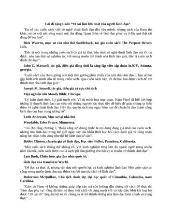
ADVANCED ENVIRO-SEPTICWASTEWATER TREATMENT SYSTEMTMWITHBIO-ACCELERATORTMTEN STEPS OF WASTEWATER TREATMENT: ADVANCED ENVIRO-SEPTICTMTREATS EFFLUENT MORE EFFICIENTLY TO PROVIDE LONGER SYSTEM LIFEAND TO PROTECT THE ENVIRONMENT.SEWN SEAMAIR SPACE10SCUM21SKIMMERS3EFFLUENT2SLUDGE8 9CROSS SECTION(NOT TO SCALE)7GEO-TEXTILEFABRIC6COARSE FORATED PLASTIC PIPEWITH EXTERIOR RIDGESSTAGE 1:WARM EFFLUENT ENTERS THE PIPE AND IS COOLED TO GROUNDWarm effluent enters the pipe and is cooled to ground OLEDLIQUIDEFFLUENT.SuspendedsolidsSEPARATEseparate FROMfrom theliquideffluent.STAGE 3:SKIMMERS FURTHER CAPTURE GREASE AND SUSPENDED SOLIDS FROM THESkimmers further capture grease and suspended solids from the existingEXITING EFFLUENT.Stage 3effluent.STAGE 4:PIPERIDGES ALLOW THE EFFLUENT TO FLOW UNINTERRUPTED AROUND THEPipe ridges allowthe effluentflowaround the circumferenceCIRCUMFERENCEOF THEPIPE ANDtoAIDIN uninterruptedCOOLING.Stage4STAGE 5:BIO-ACCELERATOR of the pipe and aidGEO-TEXTILEin cooling. FABRIC FILTERS ADDITIONAL SOLIDS FROMTHE EFFLUENT, ENHANCES AND ACCELERATES TREATMENT, FACILITATESBio-Accelerator geo-textile fabric filters additional solids from the effluent,QUICK START-UP AFTER PERIODS OF NON-USE, PROVIDES ADDITIONALenhancesandacceleratesfacilitates quickstart-up after periods ofSURFACEAREAFORBACTERIALtreatment,GROWTH, PROMOTESEVEN DISTRIBUTION,Stage 5non-use,providesadditionalsurface ANDareaTHEfor RECEIVINGbacterial growth,promotesevenANDFURTHERPROTECTSOUTER LAYERSSURFACESSOTHEYREMAIN PERMEABLE.distribution,and further protects outer layers and the receiving surfaces soSTAGE 6:A MAT OF COARSE RANDOM FIBERS SEPARATES MORE SUSPENDED SOLIDSthey remain permeable.FROM THE EFFLUENT.A mat of coarse random fibers separates more suspended solids from theSTAGEStage6 7: EFFLUENT PASSES INTO THE GEO-TEXTILE FABRIC AND GROWS A PROTECTEDeffluent. SURFACE.BACTERIALSTAGE 8:SANDWICKSLIQUIDintoFROMGEO-TEXTILEFABRICAND ENABLESAIR TOEffluentpassestheTHEgeo-textilefabricand growsa protectivebacterialStage 7TRANSFER TO THE BACTERIAL SURFACE.surface.STAGE 9:THE FABRIC AND FIBERS PROVIDE A LARGE BACTERIAL SURFACE TO BREAKSandSOLIDS.wicks liquid from the geo-textile fabric and enables air to transfer to theDOWNStage 8STAGE 10: ANAMPLE AIRSUPPLY AND FLUCTUATING LIQUID LEVELS INCREASEbacterialsurface.BACTERIALEFFICIENCY.Stage 9The fabric and fibers provide a large bacterial surface to break down solids.Stage 1STAGEStage2 2:Stage 10An ample air supply and fluctuating liquid levels increase bacterial efficiency.3
4
Section BAdvanced Enviro-Septic System ComponentsAdvancedEnviro-Septic pipe Plastic pipe made with a significant percentage of recycledmaterialEach unit is approximately 10 ft. long (can be cut easily to any length)Ridged and perforated with skimmer tabs on interiorBio-Accelerator layer aligned along bottom of pipe exteriorCovered with a mat of randomly-oriented plastic fibersSurrounded by a non-woven geo-textile fabric stitched in placeExterior diameter of 12 in.Each unit (10 ft.) has a liquid holding capacity of approx. 48 gallonsFlexible enough to bend up to 90 Offset adapterAn offset adapter is a plastic fitting with a 12 in. diameter and a hole designed toaccept a 4 in. inlet pipe, raised connection, or vent pipe. The hole is to be in thetwelve o’clock position.Note: The hole in the offset adapter will accommodate Schedule 20 to 40 PVC.Double offsetadapterA double offset adapter is a plastic fitting with a 12 in. diameter and two holesdesigned to accept a 4 in. inlet pipe, raised connection, vent or vent manifold,and/or bottom drain piping, depending upon the particular requirements of thedesign configuration.The two 4 in. holes are to be aligned in the 12 o’clock and 6 o’clock positions.The holes are positioned 1 in. from the outside edge of the double offset adaptorand 2 in. from each other.Note: The holes in the double offset adapter will accommodate Schedule 20 to 40PVC.CouplingA coupling is a plastic fitting used to create a connection between two pieces ofAdvanced Enviro-Septic pipe. The coupling features a snap-together lockingdevice and ridges that are designed to fit over the ridges of the Advanced EnviroSeptic pipe, creating a quick and easy way to join pipe sections together easilyand securely.5
Advanced Enviro-Septic System Components, continuedDistribution Box A Distribution Box, also called a “D-box,” is a device used to distribute effluentcoming from the septic tank in a system. D-boxes are also sometimes used forvelocity reduction (see p. 22). D-boxes come in various sizes and with a varyingnumber of outlets. Concrete D-boxes are preferred, some are made of plastic.Flow equalizers (see below) are installed in the D-box openings to equalizedistribution; they help ensure equal distribution in the event that the D-box settles orotherwise becomes out of level. Unused openings in D-boxes are to be covered,plugged or mortared.Flow EqualizersA flow equalizer is an adjustable plastic insert installed in the outlet holes of adistribution box to equalize effluent distribution to each outlet whenever flow isdivided.Septic Tank System SandThe Advanced Enviro-Septic System is designed to treat effluent that hasreceived “primary treatment” in a standard septic tank.Effluent filters are not recommended by Presby Environmental, Inc. due totheir tendency to clog, which cuts off the oxygen supply that is essential to thefunctioning of the Advanced Enviro-Septic System.If you are required to use an effluent filter in a gravity fed system due to stateor local requirements, the effluent filter selected must allow the free passage ofair to ensure the proper functioning of the system.The System Sand that surrounds the Advanced Enviro-Septic pipes is an essentialcomponent of the system. It is critical that the correct type and amount of SystemSand is used when constructing the system. System Sand must be coarse to verycoarse, clean, granular sand, free of organic matter. It must adhere to all of thefollowing percentage and quality restrictions: No stones over ¾ in. in diameterPercentage Restrictions (by total weight):35% maximum retained by a #10 sieve40-90% retained by a #35 sieveFines Quality Restrictions: A maximum of 5% of total sand may passthrough a #200 sieveASTM C-33 or other DOT sands may be acceptable for use as System Sandproviding that no more than 5% can pass a #200 sieve.System Sand is placed a minimum of 6 in. in all directions from the Advanced EnviroSeptic pipes (6” below pipes, 6” between rows, above pipes and around outerperimeter).6
Advanced Enviro-Septic System Components, continuedComponentHandling &Storage Keep mud, grease, oil, etc. away from all components.Avoid dragging pipe through wet or muddy areas.Store pipe on high and dry areas to prevent surface water and soil fromentering the pipes or contaminating the fabric prior to installation.The outer fabric of the Advanced Enviro-Septic pipe is ultra-violet stabilized;however, this protection breaks down after a period of time in direct sunlight.To prevent damage to the fabric, cover the pipe with an opaque tarp.7
Section CSystem Sizing, AES Pipe Requirements & Design ExampleTABLE A - Minimum Bed/Pad Area Needed (sq. ft.)PercTL-2 Loading Rate*3 Bedroom4 Bedroom5 BedroomPer Add’l. 96821200.19236831583947789AES pipe req’d. (units / ft.)21 / 210 ft.28 / 280 ft.35 / 350 ft.7 / 70 ft.The shaded areas in this table indicate parameters in which System Sand bed area will need to beIncreased in order to accommodate minimum amount AES pipe.Presby Strongly recommends that systems are designed as long and skinny as possible. Systems withPerc rates 60-120 MPI. should have a System Sand Bed a minimum of a 4:1 ratio.* Hydraulic Loading Rate has been reduced to accommodate requirements of section 12 VAC 5-61380(10) of the Regulations for Alternative Onsite Sewage SystemsTABLE B – System and Site Slope LimitationsPerc RateMaximumMaximum(minutes per inch)System SlopeSite Slope15 mpi or less25%33%16-30 mpi15%20%31-60 mpi10%15%61-120 mpiLevel (0%)(Page 43 for detail)10%8
System Sizing, AES Pipe Requirements & Design Example, continuedCalculating theAmount of AESpipe required Residential systems require a minimum of 70 ft. of AES per bedroom.(Number of bedrooms x 70 minimum AES pipe in feet.) Commercial system pipe requirements are calculated at 1 ft. of AES pipe per2 gallons per day of design flow: Commercial Daily Design Flow 2 minimum AES pipe required (in ft.).RequirementsAssume NormalDomesticStrengthEffluentSystem Sand Bed Sizing and minimum AES pipe requirements presented here weredeveloped assuming normal, domestic strength effluent which has received primarytreatment in a septic tank.DesignExampleDesign a four-bedroom residential AES System in soils with a perc rate of 30 mpi:When designing a system that will treat unusual or high strength wastes, usingadditional AES pipe is recommended. Please consult our Technical Staff at (800)473-5298 for guidance. System Sand bed area from Table A, p. 8 522 sq. ft. (minimum)Minimum AES pipe from Table A, p.8 4 bedrooms x 70 ft. 280 ft.AES Pipe Layout Examples (a few of the many possible configurations): 4 rows of pipe 70 ft. long or 7 rows of pipe 40 ft. long(uses minimum amount of pipe, 280 ft.)5 rows of pipe 60 ft. long or 6 rows of pipe 50 ft. long(row lengths rounded up to 10 ft. increments for ease of installation,uses 300 ft. of pipe)System Sand Bed Dimension Example: Assume 4 rows of pipe, 70 ft. long, System Sand bed area of 522 sq.ft.Bed length: 70 ft. row length 1 ft.* System Sand 71 ft. (* 6 in. min.,5 ft.max. System Sand required beyond the end of each row)Bed width: 522 sq. ft. 71 ft. length 7.36 ft. width (rounded up)Confirm Bed Width above will accommodate number of rows: Minimum System Sand bed width for 4 rows using 1.5 ft. center-to-centerspacing is 6.5 ft. Calculations above resulted in 7.36 ft. width, which is sufficient for 4 rows ofpipe centered in sand bed.Confirm System Sand Bed Area is sufficient: 71 ft. length x 7.36 ft. width 522 sq. ft.9
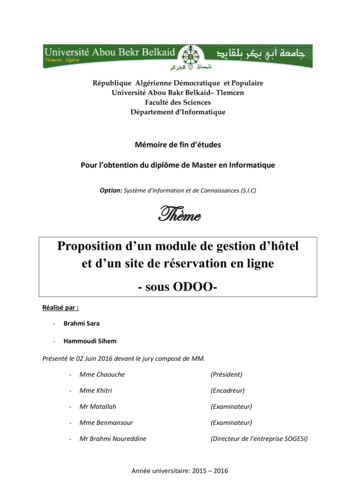
Section DSystem ConfigurationsThis section presents the various single-level design configurations of the AdvancedEnviro-Septic System. The system configuration to be used is determined by:Introduction Characteristics of the naturally-occurring soils: Percolation Rate (“perc rate,”expressed in Minutes per Inch “mpi”).The daily design flowOther characteristics specific to the particular site The following Advanced Enviro-Septic System configurations are presented in thisSection:SystemConfigurations D-box configuration (p. 10 )Multiple Bed configurations (pp. 11-12)Unique Site Solutions for any soil type (p. 13)Also in this Section: All rows in a D-box configuration must be the same length and utilize flowequalizers to ensure effluent is distributed equally to each row in the system.Use a vent manifold to ensure adequate air flow through each row (refer toillustration for D-Box Distribution Configuration below).Row lengths less than 30 ft. using this configuration are limited to use in soilswith perc rates1-60 mpi.D-Box Distribution Configuration (Level Bed)(Sloping Bed)VENT ATTACHED TO MANIFOLDD-BOX WITH FLOW EQUALIZERSD-BOX WITH FLOW EQUALIZERS6" OF SYSTEM SAND AROUNDPERIMETER OF AES PIPES6" TYP.SYSTEM SANDEXTENSIONS (IF REQ'D)6" TYP.ROW 1ROW 2ROW 3ROW 4ROW 5ROW 6ROW 3ROW 4ROW 5ROW 6SYSTEM SAND EXTENSION1.5' MIN. TYP.2.5' MIN.ROW 2VENT MANIFOLDROW 1SYSTEM SAND EXT. TYP.1.5' MIN. TYP.6" TYP.VENT MANIFOLDD-BoxDistributionConfiguration(a.k.a. “Parallel”or “Finger”configuration)Side Slope tapering and Sloping Sites/Systems (p. 14)Orientation of the pipes on the System Sand bed (p. 15)6' TYP.10VENT ATTACHED TO MANIFOLD6' MIN.
Multiple Bed DistributionIntroductionMultiple Bed distribution may be used to accommodate site constraints or to handlelarge daily design flows. It incorporates: Two or more beds Each bed receives an equal amount of effluent from a D-box with equalizers.When to useMultiple BedDistribution Flow EqualizersRequiredAll D-boxes used to divide effluent flow require flow equalizers in their outlets. Eachflow equalizer is limited to a maximum of 20 gpm in both gravity and pumped systems.BedRequirements Daily design flow is greater than 600 gpdandPerc rate is 61-120 mpiEach bed must have the same minimum total feet of pipe.Each bed must have at least two rows.The minimum linear feet of pipe per bed is determined by dividing the totallinear feet required in the Advanced Enviro-Septic System by the number ofbeds.Beds may be of different dimensions, provided that rows are not more than 100ft. long. Longer, more narrow beds work best.Recommended minimum row length is 30 ft.Rows within a bed may vary in length to accommodate site constraints. Whenrows with different lengths are used, the AES pipe must be loaded at the sameGPD/linear foot rate throughout the system.Multiple BedOrientationMultiple beds may be oriented along the contour of the site or along the slope of thesite. End-to-end configurations are preferred; however, side-to-side configurationsmay be allowed with sufficient separation distance (see Bed Separation Distances,below).Bed SeparationDistancesMinimum bed separation distances: 5 ft. separation for end-to-end system beds (measured pipe to pipe) if elevationdifference is 1 ft. or less. 10 ft. separation for end-to-end system beds (measured pipe to pipe) ifelevation difference is greater than 1 ft. but less than or equal to 3 ft. 20 ft. separation for end-to-end beds if elevation difference is greater than 3 ft. 20 ft. separation for side-to-side beds regardless of elevation difference.Minimum Bed SeparationElevationRequired BedDifferentialSeparation12 in. or less5 ft.12 in. – 36 in.10 ft. 36 in.20 ft.Side-to-Side20 ft.MEASUREPIPE TO PIPEBED #1BED #2ELEVATIONDIFFERENCE11
Multiple Bed Distribution, continuedMultiple Bed Distribution – equal linear footage of Advanced Enviro-Septic pipe in each bedBED #1BED #2VENT ATTACHED TOVENT MANIFOLD TYP.D-BOX WITH FLOWEQUALIZERSVENTMANIFOLDINLETROW 1ROW 4ROW 2ROW 5ROW 3ROW 6AS REQ'D2.5' MIN. SYSTEM SANDEXTENSION DOWNHILLFOR SLOPES OVER 5%6" OF SYSTEMAROUND PERIMETEROF ALL ROWS TYP.100' PIPE LG'TH MAX. TYP.Note: This Multiple Bed configuration may be used in all soil types. See previous page for minimum bedseparation distances.Bed separation for Side-to-Side layoutMANIFOLDED SPLITTER BOX20'SLOPED'BOX WITH FLOWEQUALIZERS TYP.VENT TYP.12
Unique Site Solutions for any soil typeIntroductionThe configurations described in this Section may be used to accommodate siteconstraints. These configurations may be used in any soil type (perc rates 1-120mpi).AnglesAngled configurations generally have one or more specific bends, but the rows shouldfollow the contour of the site. Rows are angled by bending pipes or through the use ofoffset adapters. The following layouts may be used in any soil type.Note: A 10 ft. length of Advanced Enviro-Septic pipe may be bent up to 90 .SYSTEM CURVED ABOUT RADIUSOSIONINLETSYSTEMSAND5%RAM DIIN USR5'OV ENS I ONTEBUILDING OROBSTACLEBUILDING OROBSTACLESYSTEMSANDVENTVENTCurved configurations work well around structures, setbacks, and slopes. Multiplecurves can be used if dictated by the contour of the site.RADIUS6" MINIMUM OF SYSTEM SANDAROUND PERIMETER OF PIPEVENTSINLETEX IG DR I VEWAYST I NRADIUCurvesEXTENSIONNEXINLETPEXESANDSYSTEM SANDESLNDTSLOPESAEX I S13T I NG DR I VEWAYN OVER 5%IOSYSTEMSYSTEM SAND E X TESEMNSYST
Side Slope Tapering and Sloping SystemsConfigurationnot requiringside slopetaperingIf all parts of the system, including cover material, are at or below original grade, thesystem will not require side slope tapering.Configurationrequiring sideslope tapering System Slopeand Site SlopeIf any part of the system (including soil cover) is above original grade, thesystem will require side slope tapering as illustrated below.Side slope tapering is used to blend the system into the terrain, making it bothless susceptible to erosion and less noticeable.Side slope tapering is to be a minimum of 2:1 slope; in a sloping system, sideslope tapering on the down-slope side is to be a minimum of 3:1 slope.Refer to Section I, System Sand and Fill Material Specifications, p. 28 for moreinformation about the specifications for the soil material to be used to constructside slopes.Also refer to Section L, Final Grading, pp. 34-35The percentage of slope in all illustrations refers to the slope of the Advanced EnviroSeptic System, not the existing terrain. The slope of the Advanced Enviro-Septic System and the existing terrain are not required to be equal. Refer to Table B, p. 8 formaximum system and site slopes for various soil types.14
Orientation of the Pipes on the System Sand BedSystemsSloping 5% orLessIn a system sloping 5% or less, the Advanced Enviro-Septic rows are centered onthe System Sand bed as shown in the illustrations on p. 10.SystemsSlopingMore than 5%In a system sloping greater than 5%, the Advanced Enviro-Septic rows arepositioned with 6 in. of System Sand on the up-slope side with the remaining SystemSand extending beyond the pipe on the down-slope side. In systems sloping greaterthan 5%, there must be a minimum of 3 ft. of System Sand beyond the last downslope row of pipe. Any part of the System Sand bed that is more than 6 in. awayfrom the Advanced Enviro-Septic pipe, called “System Sand Extension” needs tobe a minimum of 6 in. deep, as shown in the illustration below.Section view of grouped upslope orientation for a system sloping over 5%:Multiple slopesin one bedMultiple slopes within a single Advanced Enviro-Septic System are easilyaccommodated. If any portion of the system slopes greater than 5%, pipes aregrouped on the up-slope side of the System Sand bed, and there must be at least 3 ft.of System Sand beyond the last Advanced Enviro-Septic pipe row on the downslope side. This configuration is limited to use in soils with perc rates of 1 – 60 mpi.15
Section EDesign Criteria for Virginia Center-toCenter Spacingof Rows Center-to-center spacing of Advanced Enviro-Septic rows is a minimum of1.5 ft. for Advanced Enviro-Septic Systems.Center-to-center spacing is measured from the center of one pipe to thecenter of the pipe in the next row.Center-to-center spacing of 1.5 ft. results in the minimum of 6 in. of SystemSand between each row of Advanced Enviro-Septic pipe.Daily DesignFlowCalculationsCommercialCommercial systems will use 1 ft. of AES pipe for every 2 gpd of daily design flow:Daily design flow (gal/day) 2 Minimum AES pipe (ft.)Daily DesignFlowCalculationsResidentialResidential daily design flows are calculated based on 150 gallons per day (“gpd”)per bedroom.D-Box Manifold Note: All designs for commercial systems are required to be prepared by aProfessional Engineer in Virginia.A D-box manifold is utilized to equalize flow.Flow equalizers should be used on all D-box outlets.Unused D-box outlets must be covered, plugged or mortared.This configuration is especially useful when designing for large daily designflows. See “Velocity Reduction,” this Section, p. 21.Distribution box manifold is used to divide flow evenly to separate beds or sections:TO BED #1D-BOXINLETUNUSEDOUTLETSD-BOXUSE OUTLETSAS NEEDEDD-BOX4" Ø PVCTYPICALTO BED #2Note: Utilizing every other outlet will provide room for required piping and allow foreasier installation. Install flow equalizers on all used outlets.16
Design Criteria for Virginia, continuedEnd-to-EndPreferred OverSide-to-sideIf site conditions permit, end-to-end system bed configurations are preferable toside-to-side system bed configurations. See illustrations on p. 12.Filters GarbageDisposals All septic tanks must be equipped with baffles or tees to reduce the amount ofsolids exiting the tank and entering the Advanced Enviro-Septic System.Effluent filters are not recommended by Presby Environmental, Inc. due totheir tendency to clog, which cuts off the oxygen supply that is essential to thefunctioning of the Advanced Enviro-Septic System.If you are required to use an effluent filter in a gravity fed system due to stateor local requirements, the effluent filter selected must allow the free passage ofair to ensure the proper functioning of the system.If a garbage disposal is utilized, we recommend that the required liquidcapacity of the septic tank be increased by 50%.Multiple compartment septic tanks or multiple tanks are preferred.If a garbage disposal is used, the septic tank will likely require more frequentpumping (see Operation & Maintenance, Section M, p. 36).HorizontalSeparationDistancesMinimum horizontal separation distances (also called “set-backs”) must comply withstate and/or local requirements. Horizontal separation distances are measured fromthe outermost edge of the System Sand bed.InterceptorDrainsInterceptor Drains, if used, must be upslope of the AES System and a minimum of 10ft. away from all AES pipes. AES pipe is excellent for use in constructing interceptordrains.Maximum RowLengthsTo maintain efficient cycling within the AES pipe, the maximum row length is 100 ft.The longest, narrowest system design practical for the site is recommended tofacilitate infiltration.MinimumNumber ofRowsAll beds must have at least 2 parallel rows.17
Design Criteria for Virginia, continuedOrientation ofPipes onSystem SandBedFor Advanced Enviro-Septic Systems sloping less than or equal to 5%, the SystemSand extends horizontally a minimum of 6 in. beyond the outer perimeter of theAdvanced Enviro-Septic pipes, with the pipes centered on the System Sand bed.For systems sloping from over 5% up to 25%, the Advanced Enviro-Septic rows arepositioned (grouped) 6 in. from the up-slope edge of the System Sand bed. Aminimum of 3 ft. of System Sand is required beyond the last down-slope row. Anypart of the System Sand bed more than 6 in. away from the Advanced EnviroSeptic pipe (called “System Sand Extension”) is a minimum of 6 in. deep.Refer to Table B, p. 8 for slope limitationsSee illustrations on p. 10Pipe Length(Minimum)RequiredPumped S
By utilizing simple yet effective natural processes, the Advanced Enviro-Septic Treatment System treats septic tank effluent in a manner that prevents suspended solids from sealing the underlying soil, increases system aeration, and provides a greater bacterial area ("biomat") than conventional septic systems. Why is Advanced Enviro-Septic