Transcription
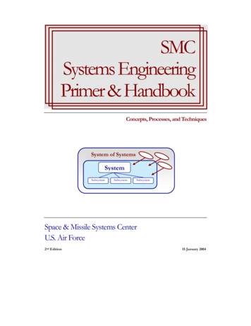
SMCSystems EngineeringPrimer & HandbookConcepts, Processes, and TechniquesSystem of SystemsSystemSubsystemSubsystemSubsystemSpace & Missile Systems CenterU.S. Air Force2nd Edition15 January 2004
SMC Systems EngineeringSMC Systems EngineeringConcepts, Processes, and Techniquesi
iiSMC Systems Engineering
SMC Systems EngineeringiiiTable of ContentsForeword. xiPreface . xiiAcknowledgments . xiiiChapter 1 SMC Systems Engineering Primer. 1What is a System?. 1Military Systems . 1Types of System Elements . 1What is a Space System? . 2What’s different about a Space System?. 2The Space Environment . 2Unattended Operation . 3The Ultimate High Ground. 3What is a Family of Systems or a System of Systems? . 4What is a System Acquisition Program? (How does a military system come to be?). 4Department of Defense (DoD) Process for Acquiring a System . 5What is a System Capability Need (or Requirement)?. 6What is a Technical Requirement or Constraint?. 7The System Environment . 8What are Interfaces?. 8What is Architecture or a System Architecture?. 9Architectural Standards . 10CJCS Definition . 10Open-Standards Systems Architecture Approach . 10Why OSSA. 11What is Forward Compatibility? . 12The C4ISR Architecture Framework. 12Architecture–A Recap . 12What is Systems Engineering?. 13What is the Systems Engineering Process?. 16Requirements Analysis and Concept Refinement . 16Further Concept and System Development and Design . 22Completion of Development and the Product Configuration Baseline . 27What is the Relationship of Systems Engineering to Program Management? . 31How We Got to Where We Are? . 33Why is Systems Engineering Useful? . 35Chapter 2 How Does the Systems Engineering Process Work? . 37The Capability Needs Process. 37Functional Area Analysis . 38Functional Needs Analysis. 38Functional Solution Analysis . 38
ivSMC Systems EngineeringJCIDS Process and Document Descriptions. 39JCIDS Document Descriptions . 39The Systems Engineering Process . 41Requirements Analysis . 43Missions and Environments Analysis . 44Functional Requirements Identification . 45Performance Requirements and Design Constraints Definition and Refinement. 45Functional Analysis and Allocation . 45Decomposition . 46Allocation. 47Functional Architecture. 47Interfaces . 48Synthesis . 48Architecture Transformation . 50C4ISR Architecture Framework. 51Alternate System Concepts and Elements Definition. 51Physical Interfaces Definition . 52Alternate Product and Process Definition . 52Work Breakdown Structure (WBS). 53System Analysis and Control. 54Trade Studies and Analyses . 55A Few Words About Time. 57Chapter 3 Life Cycle Phases of a Major System . 59Pre-KDP-A (Concept Refinement) . 60Phase A–Study Phase (Technology Development). 61Phase B–Design Phase (System Development & Demonstration) . 63Phase C–-Build, Test Launch (Production & Deployment, Operations & Support). 64Phase C1–Build, Test (Production) . 64Phase C2–Launch (Deployment). 66Phase C3– Operations & Support. 66Phase C4–Disposal. 66Systems Engineering–Software Development . 69Systems Software Development. 70Evolution of Software Development Standards . 70Software Acquisition Strategy Considerations. 71Software Development Lifecycle . 72Chapter 4 What is Systems Engineering Management? . 77What is Management?. 78Relationship of Systems Engineering Management to Overall Program Cost, Schedule andRisk . 79Planning and Organizing. 80Systems Engineering Process Selection . 81
SMC Systems EngineeringvIntegrated Master Plan (IMP) Narrative/Systems Engineering Management Plan (SEMP). 81The Work Breakdown Structure. 82Staffing and Direction. 82Monitoring and Control . 83Earned Value Management (EVMS). 83Reviews and Audits. 84Metrics and Measurement Assessments . 85Technical Performance Measurements (TPM). 85Systems Analysis–the Trade Study Process . 87Cost Estimating . 88Risk Management . 89Example Approach to Implementing Risk Management. 91Risk Management Summary . 92Interface Management . 93Interface Control Plan Outline. 93Change Management/Configuration Management . 94Configuration Identification . 95CM Monitoring and Control. 95Configuration Status Accounting . 95Configuration Audits. 96Data Management . 96Operational Safety, Suitability, and Effectiveness (OSS&E) . 96Chapter 5 What are the System Engineer’s Tools?. 99Overview of Engineering Tools Usage by Acquisition Phase . 99Modeling & Simulation (M&S) Tools. 99Defense Modeling & Simulation Office (DMSO) . 100High Level Architecture (HLA) . 100HLA Federate Compliance Testing. 100Concept or System Architecture Tools . 101Analytical Tools. 102Architecture Analysis . 102Requirements & Design Analysis Tools . 104Requirements Change Management Tools. 121System Analysis and Control Tools . 122Process Capability Models . 122Program/Project Management Tools. 124Tools Summary. 125Chapter 6 What are the Companion Disciplines to Systems Engineering? . 127Design . 127Research & Technologies . 128Manufacturing & Producibility. 129
viSMC Systems EngineeringReliability & Maintainability . 129Reliability. 129Maintainability . 131Mass Properties. 132Environments & Survivability . 132Environmental, Health and Safety . 133Human Engineering–Personnel Subsystems. 134Training. 134Quality Assurance. 135Integrated Logistics Support . 136Chapter 7 Validation and Verification . 139Validation and Verification Methods. 140Testing . 141Test and Evaluation . 142Design for Testing . 143Integrating Test and Evaluation . 143Reducing Integration and Test Time. 143Chapter 8 Summary . 145INCOSE. 146So Many Interfaces, So Little Time . 146Appendix A–Glossary . 149Appendix B–Acronyms . 167Appendix C–Templates and Examples . 173Appendix C1–A Sample SEMP Outline . 174Appendix C2– “Tailored” WBS for a Launch & Satellite System . 176WBS Definitions . 177Appendix C4–Risk Identification Trigger List . 197Systems Engineering and Technical Risk Questions. 197Cost Risk Questions . 197Schedule Risk Questions . 198Program Management Risk Questions . 198Software Risk Questions . 199Manufacturing/Producibility Risk Questions . 199Systems Integration . 200Appendix C5–Techniques of Functional Analysis. 201Functional Analysis Processes . 201Appendix C6–Example of System Allocation and Assessment Process. 209Appendix C7–TPM Examples Using the Hierarchy Methodology. 213TPM Hierarchy Example. 213Appendix C8–Example Trade Study Outline . 216Appendix C9–Technology Readiness Levels . 218Appendix C10–States & Modes. 219
SMC Systems EngineeringviiAppendix C11–C4ISR Architecture Framework . 222Appendix C12–Example of Threat Evaluation & CAIV Study . 224Appendix C13–Summary Checklist for an OSS&E Plan . 227General . 227Stakeholders . 227OSS&E Key Elements. 227Certifications . 228Inspections and Maintenance . 228Operations and Maintenance . 229Technology Demonstration . 229Schedule . 229Budget . 229Reviews and Certificates . 229Maintenance of the OSS&E Baseline. 230Appendix C14–Example Requirements Allocation Sheet . 232Appendix C15–Requirements Evaluation and Acceptability Criteria. 233Appendix D–References and Bibliography . 235Systems Engineering Methodology . 235Joint Application Design. 236Pugh Controlled Convergence . 236NXN Chart. 236Optimization . 236Taguchi Methods . 236Department of Defense Instructions and Guidance. 236Appendix E–Customer Review & Feedback Form. 239Index . 241
viiiSMC Systems EngineeringList of FiguresFigure 1. The personal computer system . 1Figure 2. A Family of Systems–sensor to intelligence fusion center to shooter to weapon. 4Figure 3. Key steps in the JCIDS process. 7Figure 4. Engineering process to develop a system . 15Figure 5. Simplified systems engineering process. 17Figure 6. Cost effectiveness curve . 21Figure 7. Systems engineering process for design . 23Figure 8. A top level functional flow block diagram showing a simple, generic relationshipamong the eight primary life cycle functions . 24Figure 9. A simple satellite system physical hierarchy (product tree) . 25Figure 10. Overall systems engineering process. 28Figure 11. JCIDS top-down capability need identification process. 38Figure 12. JCIDS process and acquisition decisions . 39Figure 13. The systems engineering process . 42Figure 14. Requirement analysis–converting customer needs into system requirements . 44Figure 15. Functional analysis & allocations–create lower level requirements to aid synthesisof solutions . 46Figure 16. Notional functional architecture–integration of space systems functions withexisting space assets . 49Figure 17. Synthesis–developing detailed solutions . 50Figure 18. A sample WBS of a launch system . 54Figure 19. System analysis & control . 55Figure 20. The defense acquisition management framework . 59Figure 21. NSS acquisition phases. 60Figure 22. Waterfall method. 72Figure 23. Spiral development lifecycle model . 73Figure 24. Typical relationship of capabilities and other program inputs to cost, schedule,and risk . 80Figure 25. Metrics development and reporting process . 85Figure 26. Performance measures tracked over time . 86Figure 27. Trade studies to resolve architectures, requirements, and functional & designsolutions . 88Figure 28. A risk assessment approach. 92Figure 29. OSS&E assurance process. 97Figure 30. The DoD modeling & simulation community . 100Figure 31. Cross correlation Charts–products features checklists . 105Figure 32. Self-interaction charts–showing which factors affect others . 106Figure 33. Standard NXN (4X4) chart. 106Figure 34. NxN showing graphical interelationships. 107Figure 35. Utility curves–providing insight into criteria sensitivity . 110Figure 36. QFD representation–house of quality. 112
SMC Systems EngineeringixFigure 37. A full house of quality–added rooms for greater QFD definition. 113Figure 38. House of quality–new rooms. 114Figure 39. Concept evaluation and comparison matrix . 114Figure 40. PSM bubble chart . 117Figure 41. Robust design may be better than optimum . 118Figure 42. Balanced Experiments can Reduce Experimentation Costs and Schedule . 119Figure 43. CMMITM model components. 124Figure 44. Sample functional flow block diagram (FFBD)–typical symbols used in FFBDs . 204Figure 45. Sample functional flow diagram–showing interrelation of various levels. 207Figure 46. Timeline sheets–show sequence of operational and concurrent action . 208Figure 47. Reliability functions calculated for each major element of satellite. 210Figure 48. Probability of loss of one or both satellites due to random failure .
familiar to SMC. It also provides information on recommended systems engineering practices and pitfalls to avoid. Many references are provided for the reader to consult for more in-depth knowledge. This handbook describes systems engineering as it could be applied to the development of major space and launch systems.
