Transcription
xxZZZMSO2000B, DPO2000B, MSO2000 and DPO2000Series OscilloscopesProgrammer Manual*P077073800*077-0738-00
xxZZZMSO2000B, DPO2000B, MSO2000 and DPO2000Series OscilloscopesProgrammer ManualRevision Awww.tektronix.com077-0738-00
Copyright Tektronix. All rights reserved. Licensed software products are owned by Tektronix or its subsidiariesor suppliers, and are protected by national copyright laws and international treaty provisions.Tektronix products are covered by U.S. and foreign patents, issued and pending. Information in this publicationsupersedes that in all previously published material. Specifications and price change privileges reserved.TEKTRONIX and TEK are registered trademarks of Tektronix, Inc.Contacting TektronixTektronix, Inc.14150 SW Karl Braun DriveP.O. Box 500Beaverton, OR 97077USAFor product information, sales, service, and technical support:In North America, call 1-800-833-9200.Worldwide, visit www.tektronix.com to find contacts in your area.
Table of ContentsGetting Started .Setting Up Remote Communications Hardware .Connecting via Ethernet.Connecting via USB .Connecting via GPIB .Setting Up Remote Communications Software .Using TekVISA .Using Tektronix e*Scope Software .Documentation .Command Syntax.Command and Query Structure .Clearing the oscilloscope .Command Entry.Constructed Mnemonics .Argument Types.Command Groups .Acquisition Command Group .Alias Command Group.Bus Command Group .Calibration and Diagnostic Command Group .Cursor Command Group .Display Command Group.Ethernet Command Group .File System Command Group .FilterVu Command Group .Hard Copy Command Group .Horizontal Command Group .Mark Command Group.Math Command Group.Measurement Command Group .Miscellaneous Command Group .PictBridge Command Group .Save and Recall Command Group .Search Command Group .Status and Error Command Group .Trigger Command Group .Vertical Command Group.Waveform Transfer Command Group .Zoom Command Group .MSO2000B, DPO2000B, MSO2000 and DPO2000 Series Oscilloscopes Programmer -232-252-262-292-302-312-332-372-382-472-502-57i
Table of ContentsCommands Listed in Alphabetical Order .Status and Events .Registers .Queues .Event Handling Sequence.Synchronization Methods .Messages.Appendix A: Character Set .Appendix B: Waveform Data in MSO/DPO2000B and MSO/DPO2000 Series Instruments.Appendix C: Reserved Words .Appendix D: Application Module-enabled Commands .Appendix E: Search and Trigger Command Sequence Examples.Example 1: Single Threshold Edge Search .Example 2: Single Threshold Edge Trigger .Example 3: Dual Threshold Runt Search .Example 4: Single Threshold Logic Search on Three -1E-1E-1E-1E-2E-2MSO2000B, DPO2000B, MSO2000 and DPO2000 Series Oscilloscopes Programmer Manual
Getting StartedThis manual explains the use of commands for remotely controlling youroscilloscope. With this information, you can write computer programs toperform functions, such as setting the front-panel controls, taking measurements,performing statistical calculations, and exporting data for use in other programs.This manual describes commands for the following models:Table 1-1:ModelBandwidthNumberof AnalogChannelsMSO2024B,MSO2024200 MHz41 GS/s1 M pts.5,000MSO2022B200 MHz21 GS/s1 M pts.5,000MSO2014B,MSO2014100 MHz41 GS/s1 M pts.5,000MSO2012B,MSO2012100 MHz21 GS/s1 M pts.5,000MSO2004B70 MHz41 GS/s1 M pts.5,000MSO2002B70 MHz21 GS/s1 M pts.5,000DPO2024B,DPO2024200 MHz41 GS/s1 M pts.5,000DPO2022B200 MHz21 GS/s1 M pts.5,000DPO2014B,DPO2014100 MHz41 GS/s1 M pts.5,000DPO2012B,DPO2012100 MHz21 GS/s1 M pts.5,000DPO2004B70 MHz41 GS/s1 M pts.5,000DPO2002B70 MHz21 GS/s1 M pts.5,000New in the ProgrammerManualSample RateRecord Length,all ch.Wfm. CaptureRateThe following major changes were made to this version of the programmermanual (077-0738-00):Added 6 new oscilloscope models:MSO2002B – 70 MHz, 2 channelMSO2004B – 70 MHz, 4 channelMSO2022B – 200 MHz, 2 channelDPO2002B – 70 MHz, 2 channelDPO2004B – 70 MHz, 4 channelMSO2000B, DPO2000B, MSO2000 and DPO2000 Series Oscilloscopes Programmer Manual1-1
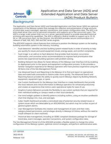
Getting StartedDPO2022B – 200 MHz, 2 channelSetting Up Remote Communications HardwareYou can remotely communicate between your oscilloscope and PC via Ethernet,USB, or GPIB cables.NOTE. In order to communicate via an Ethernet cable, you need to install anoptional DPO2CONN Connectivity Module into the back of the instrument. Thismodule includes both Ethernet and VGA video monitor ports.Connecting via EthernetIf your PC is connected to a local area network, you can use an Ethernet cable toconnect your oscilloscope to the same network, and then use software to remotelycontrol the oscilloscope via the PC. First, you’ll need to acquire an optionalDPO2CONN Connectivity Module, which provides Ethernet and video out portsfor your oscilloscope (search on www.tektronix.com). Then, simply plug one endof the Ethernet cable into the Ethernet port (RJ-45 connector), and the other endinto your network connection.NOTE. You can connect an MSO/DPO2000B oscilloscope only to a 10/100Base-T local area network.1-2MSO2000B, DPO2000B, MSO2000 and DPO2000 Series Oscilloscopes Programmer Manual
Getting StartedTo view or change the Ethernet settings on your oscilloscope, do the following:1. On the front panel, push Utility.2. Push Utility Page.3. Select I/O with the Multipurpose knob.4. Push Ethernet Network Settings.5. If you are on a DHCP Ethernet network and using a through cable, on theside menu set DHCP/BOOTP to On.6. If you are using a cross-over cable, set DHCP/BOOTP to Off, and set ahard-coded TCPIP address.Connecting via USBYou can connect your oscilloscope directly to a PC by using a high-speed USBcable, and then use software to remotely control the oscilloscope via the PC.Simply plug one end of the cable into the USB 2.0 high-speed device port onthe rear panel of your oscilloscope, and the other end into a USB port on yourcomputer.This port requires that the cable connected from the port to the host computermeets the USB 2.0 specification for high speed connections. Typically, suchcables should be 3 feet or shorter in length, but this is determined by the quality ofthe cable and, with higher quality cables, this length can be extended. (It is alsodependent upon the drive capability of the host USB port to which the instrumentis connected.) The use of high quality short cables is recommended to avoid USBconnection problems.Once the USB cable is connected, the system automatically configures itself. Toverify that the USB is enabled:1. On the front panel, push Utility.2. Push Utility Page.3. Select I/O with the Multipurpose knob.4. Push USB, and verify that USB is enabled.5. If USB is not enabled, push Enabled on the side menu.After connection, the host, with appropriate software, can list the oscilloscope as aUSB device with the following parameters: (See Table 1-2.)MSO2000B, DPO2000B, MSO2000 and DPO2000 Series Oscilloscopes Programmer Manual1-3
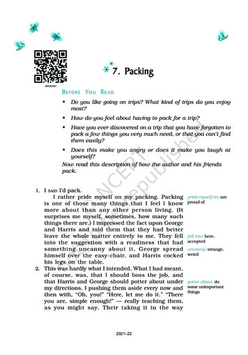
Getting StartedTable 1-2: USB Device ParametersParameterConnecting via GPIBValueManufacturer ID0x0699 (decimal 1689)Product ID0x399 DPO2002B0x39A MSO2002B0x39B DPO2004B0x39C MSO2004B0x39D DPO2012B0x39E MSO2012B0x39F DPO2014B0x3A0 MSO2014B0x3A1 DPO2022B0x3A2 MSO2022B0x3A3 DPO2024B0x3A4 MSO2024B0x0372 DPO20120x0373 DPO20140x0374 DPO20240x0376 MSO20120x0377 MSO20140x0378 MSO2024Serial numberSerial numberManufacturer description“Tektronix”Interface description“USBTMC-USB488”(decimal 921)(decimal 922)(decimal 923)(decimal 924)(decimal 925)(decimal 926)(decimal 927)(decimal 928)(decimal 929)(decimal 930)(decimal 931)(decimal 932)The oscilloscope has a USB 2.0 high-speed device port to control the oscilloscopethrough USBTMC or GPIB with a TEK-USB-488 Adapter. The USBTMCprotocol allows USB devices to communicate using IEEE488 style messages.This lets you run your GPIB software applications on USB hardware.To use GPIB, start by connecting an appropriate USB cable to the USB 2.0high-speed device port on the rear panel of your oscilloscope. Connect the otherend to the TEK-USB-488 Adapter host port. Then connect a GPIB cable from theTEK-USB-488 Adapter to your PC.Supply power to the Adapter in either of these two ways:1-4MSO2000B, DPO2000B, MSO2000 and DPO2000 Series Oscilloscopes Programmer Manual
Getting Started1. Use the optional 5 VDC power adapter connected to the 5 VDC power inputon the Adapter.2. Use an appropriate USB cable connected to a powered USB host port on yourPC and the Device port on the TEK-USB-488 Adapter.Before setting up the oscilloscope for remote communication using the electronic(physical) GPIB interface, you should familiarize yourself with the followingGPIB requirements:A unique device address must be assigned to each device on the bus. No twodevices can share the same device address.No more than 15 devices can be connected to any one line.Only one device should be connected for every 6 feet (2 meters) of cable used.No more than 65 feet (20 meters) of cable should be used to connect devicesto a bus.At least two-thirds of the devices on the network should be powered on whileusing the network.Connect the devices on the network in a star or linear configuration. Do notuse loop or parallel configurations.To function correctly, your oscilloscope must have a unique device address. Thedefault setting for the GPIB configuration is GPIB Address 1.To change the GPIB address settings, do the following:1. On the front panel, push Utility.2. Push Utility Page.3. Select I/O with the Multipurpose knob.4. Push GPIB.5. Enter the GPIB address on the side menu, using the multipurpose knob. Thiswill set the GPIB address on an attached TEK-USB-488 AdapterThe oscilloscope is now set up for bidirectional communication with your PC.Setting Up Remote Communications SoftwareConnect your oscilloscope directly to a computer to let the PC analyze your data,collect screen images, or to control the oscilloscope using a program of your owncreation. You can connect using TekVISA drivers, or connect directly from anycomputer’s web browser using Tektronix e*Scope Web-enabled tools.MSO2000B, DPO2000B, MSO2000 and DPO2000 Series Oscilloscopes Programmer Manual1-5
Getting StartedNOTE. The CD that your oscilloscope shipped with contains additional tools forefficient connectivity between your oscilloscope and your computer. These includetoolbars that speed connectivity with Microsoft Excel and Word.Using TekVISATekVISA lets you use your MS-Windows computer to acquire data from youroscilloscope for use in an analysis package that runs on your PC, such as MicrosoftExcel, National Instruments LabVIEW, Tektronix OpenChoice Desktop software,or your own custom software. You can use a common communications connection,such as USB, Ethernet, or GPIB, to connect the computer to the oscilloscope.The TekVISA drivers are automatically installed by installing the OpenChoiceDesktop software that came with your instrument’s CD. You can also downloadthe OpenChoice Desktop software from www.tektronix.com\downloads.NOTE. TekVISA cannot run if any other version of VISA drivers is installed.To set up communications between your oscilloscope and a computer runningTekVISA drivers:1-6MSO2000B, DPO2000B, MSO2000 and DPO2000 Series Oscilloscopes Programmer Manual
Getting Started1. Install the Tektronix OpenChoice Desktop software package, either from theCD that came with your instrument or from the Tektronix website. This willautomatically install the TekVISA drivers.2. Connect the oscilloscope to your computer with the appropriate USB, Ethernetor GPIB cable. Cycle the power on the oscilloscope.3. Push Utility.4. Push Utility Page.5. Turn multipurpose knob a and select I/O.6. If you are using USB, the system sets itself up automatically for you, if USB isenabled. Check USB on the lower menu to be sure that USB is enabled. If it isnot enabled, push USB. Then push Connect to Computer on the side menu.7. To use Ethernet, push Ethernet Network Settings on the lower menu. Usethe side menu buttons to adjust your network settings, as needed. For moreinformation, see the e*Scope setup information below.8. If you are using GPIB, push GPIB. Enter the GPIB address on the side menu,using multipurpose knob a. This will set the GPIB address on an attachedTEK-USB-488 Adapter.9. Run the application software on your computer.Using Tektronix e*ScopeSoftwareYour oscilloscope contains a pre-installed remote control software package byTektronix called e*Scope. You can use this to “talk” to a networked PC’s webbrowser so that you can view and control the oscilloscope wherever it is on yournetwork.First, you’ll need to acquire an optional DPO2CONN Connectivity Module,which provides Ethernet and video out ports for your oscilloscope (search onwww.tektronix.com).MSO2000B, DPO2000B, MSO2000 and DPO2000 Series Oscilloscopes Programmer Manual1-7
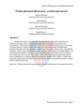
Getting StartedTo set up e*Scope communications between your oscilloscope and a networkedcomputer:1. With the DPO2CONN Connectivity Module installed, connect an Ethernetcable from the back of the oscilloscope to the same network as your computer.2. Power up your oscilloscope and test the network connection:a. Push the Utility button, and then push Utility Page on the bottom menu.b. Turn multipurpose knob a to select I/O, and then push Ethernet NetworkSettings on the bottom menu.c. Push Test Connection on the side menu. The button should say OK.3. Next, find your oscilloscope’s IP address:a. Push Change Instrument Settings on the side menu to display thenetwork parameters configured on your oscilloscope.b. Note down the Instrument IP address.1-8MSO2000B, DPO2000B, MSO2000 and DPO2000 Series Oscilloscopes Programmer Manual
Getting Started4. On the menu bar of your PC’s web browser, type in the oscilloscope’sInstrument IP address and press Enter.5. You should now see the e*Scope screen on your PC and an image of youroscilloscope’s display. You may use the menu items at the top to control youroscilloscope from your PC’s browser.DocumentationThe following documents are available for download on the Manuals FinderWeb site at www.tektronix.com:MSO/DPO2000B Series User Manual. Information about installing andoperating the oscilloscope.MSO/DPO2000B Series Technical Reference. Oscilloscope specifications anda performance verification procedure.TekVISA Programmer Manual. Description of TekVISA, the Tektroniximplementation of the VISA Application Programming Interface (API). TekVISAis industry-compliant software for writing interoperable oscilloscope drivers in avariety of Application Development Environments (ADEs).MSO2000B, DPO2000B, MSO2000 and DPO2000 Series Oscilloscopes Programmer Manual1-9
Getting Started1-10MSO2000B, DPO2000B, MSO2000 and DPO2000 Series Oscilloscopes Programmer Manual
Command SyntaxYou can control the operations and functions of the oscilloscope through theEthernet port or the USB 2.0 device port using commands and queries. Therelated topics listed below describe the syntax of these commands and queries.The topics also describe the conventions that the oscilloscope uses to processthem. See the Command Groups topic in the table of contents for a listing of thecommands by command group, or use the index to locate a specific command.Backus-Naur FormNotationThis documentation describes the commands and queries using Backus-NaurForm (BNF) notation. Refer to the following table for the symbols that are used.Table 2-1: Symbols for Backus-Naur FormSymbol Meaning Is defined as Exclusive ORDefined element{}Group; one element is required[]. .Optional; can be omitted()CommentPrevious element(s) may be repeatedCommand and Query StructureCommands consist of set commands and query commands (usually calledcommands and queries). Commands modify oscilloscope settings or tell theoscilloscope to perform a specific action. Queries cause the oscilloscope to returndata and status information.Most commands have both a set form and a query form. The query form of thecommand differs from the set form by its question mark at the end. For example,the set command ACQuire:MODe has a query form ACQuire:MODe?. Not allcommands have both a set and a query form. Some commands have set only andsome have query only.MessagesA command message is a command or query name followed by any informationthe oscilloscope needs to execute the command or query. Command messagesmay contain five element types, defined in the following table.MSO2000B, DPO2000B, MSO2000 and DPO2000 Series Oscilloscopes Programmer Manual2-1
Command SyntaxTable 2-2: Command Message ElementsCommandsSymbolMeaning Header This is the basic command name. If the header ends with a questionmark, the command is a query. The header may begin with a colon(:) character. If the command is concatenated with other commands,the beginning colon is required. Never use the beginning colon withcommand headers beginning with a star (*). Mnemonic This is a header subfunction. Some command headers have only onemnemonic. If a command header has multiple mnemonics, a colon (:)character always separates them from each other. Argument This is a quantity, quality, restriction, or limit associated with the header.Some commands have no arguments while others have multiplearguments. A space separates arguments from the header. A comma separates arguments from each other. Comma A single comma is used between arguments of multiple-argumentcommands. Optionally, there may be white space characters beforeand after the comma. Space A white space character is used between a command header and therelated argument. Optionally, a white space may consist of multiplewhite space characters.Commands cause the oscilloscope to perform a specific function or change one ofthe settings. Commands have the structure:[:] Header [ Space Argument [ Comma Argument ].]A command header consists of one or more mnemonics arranged in a hierarchicalor tree structure. The first mnemonic is the base or root of the tree and eachsubsequent mnemonic is a level or branch off the previous one. Commands at ahigher level in the tree may affect those at a lower level. The leading colon (:)always returns you to the base of the command tree.2-2MSO2000B, DPO2000B, MSO2000 and DPO2000 Series Oscilloscopes Programmer Manual
Command SyntaxQueriesQueries cause the oscilloscope to return status or setting information. Querieshave the structure:[:] Header [:] Header [ Space Argument [ Coma Argument ].]You can specify a query command at any level within the command tree unlessotherwise noted. These branch queries return information about all the mnemonicsbelow the specified branch or level.HeadersUse the HEADer command to control whether the oscilloscope returns headers aspart of the query response. If header is on, the query response returns commandheaders, then formats itself as a valid set command. When header is off, theresponse includes only the values. This may make it easier to parse and extract theinformation from the response. The table below shows the difference in responses.Table 2-3: Comparison of Header Off and Header On ResponsesQueryHeader OffHeader OnTIME?14:30:00:TIME “14:30:00”ACQuire:NUMAVg?100:ACQUIRE:NUMAVG 100MSO2000B, DPO2000B, MSO2000 and DPO2000 Series Oscilloscopes Programmer Manual2-3
Command SyntaxClearing the oscilloscopeYou can clear the Output Queue and reset the oscilloscope to accept a newcommand or query by using the selected Device Clear (DCL) function.Command EntryThe following rules apply when entering commands:You can enter commands in upper or lower case.You can precede any command with white space characters. White spacecharacters include any combination of the ASCII control characters 00 through09 and 0B through 20 hexadecimal (0 through 9 and 11 through 32 decimal).The oscilloscope ignores commands consisting of any combination of whitespace characters and line feeds.AbbreviatingYou can abbreviate many oscilloscope commands. Each command in thisdocumentation shows the minimum acceptable abbreviations in capitals. Forexample, you can enter the command ACQuire:NUMAvg simply as ACQ:NUMAor acq:numa.Abbreviation rules may change over time as new oscilloscope models areintroduced. Thus, for the most robust code, use the full spelling.If you use the HEADer command to have command headers included as partof query responses, you can further control whether the returned headers areabbreviated or are full-length with the VERBose command.Concatenating2-4You can concatenate any combination of set commands and queries using asemicolon (;). The oscilloscope executes concatenated commands in the orderreceived.MSO2000B, DPO2000B, MSO2000 and DPO2000 Series Oscilloscopes Programmer Manual
Command SyntaxWhen concatenating commands and queries, you must follow these rules:1. Separate completely different headers by a semicolon and by the beginningcolon on all commands except the first one. For example, the commandsTRIGger:MODe NORMal and ACQuire:NUMAVg 8, can be concatenatedinto the following single command:TRIGger:MODe NORMal;:ACQuire:NUMAVg 82. If concatenated commands have headers that differ by only the last mnemonic,you can abbreviate the second command and eliminate the beginning colon.For example, you can concatenate the commands ACQuire:MODe AVErageand ACQuire:NUMAVg 8 into a single command:ACQuire:MODe AVErage; NUMAVg 8The longer version works equally well:ACQuire:MODe AVErage;:ACQuire:NUMAVg 83. Never precede a star (*) command with a colon:ACQuire:STATE 1;*OPCAny commands that follow will be processed as if the star command wasnot there so the commands, ACQuire:MODe ENVelope;*OPC;NUMAVg 8will set the acquisition mode to envelope and set the number of acquisitionsfor averaging to 8.4. When you concatenate queries, the responses to all the queries areconcatenated into a single response message.5. Set commands and queries may be concatenated in the same message. Forexample,ACQuire:MODe SAMple;NUMAVg?;STATE?is a valid message that sets the acquisition mode to sample. The message thenqueries the number of acquisitions for averaging and the acquisition state.Concatenated commands and queries are executed in the order received.Here are some invalid concatenations:HORizontal:SCAle 400E-9;ACQuire:NUMAVg 8 (no colon beforeACQuire)DISPlay:GRAticule FULL;:*TRG (colon before a star (*) command)MATH:HORizontal:SCAle 1.0e-1;HORizontal:POSition 5.0el(levels of the mnemonics are different; either remove the second use ofHORizontal: or place :MATH in front of HORizontal:POSition)TerminatingThis documentation uses EOM (End of Message) to represent a messageterminator.MSO2000B, DPO2000B, MSO2000 and DPO2000 Series Oscilloscopes Programmer Manual2-5
Command SyntaxTable 2-4: End of Message TerminatorSymbolMeaning EOM Message terminatorThe end-of-message terminator must be the END message (EOI assertedconcurrently with the last data byte). The last data byte may be an ASCII linefeed (LF) character.This oscilloscope does not support ASCII LF only message termination. Theoscilloscope always terminates outgoing messages with LF and EOI.Constructed MnemonicsSome header mnemonics specify one of a range of mnemonics. For example, achannel mnemonic can be CH1, CH2, CH3, or CH4. You use these mnemonicsin the command just as you do any other mnemonic. For example, there is aCH1:POSition command, and there is also a CH2:POSition command. In thecommand descriptions, this list of choices is abbreviated as CH x .Cursor PositionMnemonicsWhen cursors are displayed, commands may specify which cursor of the pair touse.Table 2-5: Channel MnemonicsSymbolMeaningCH x A channel specifier; x is 1 through 4.Table 2-6: Cursor MnemonicsMath Specifier MnemonicsSymbolMeaningCURSOR x A cursor selector; x is either 1 or 2.POSITION x A cursor selector; x is either 1 or 2.HPOS x A cursor selector; x is either 1 or 2.Commands can specify the mathematical waveform to use as a mnemonic inthe header.Table 2-7: Math Specifier Mnemonics2-6SymbolMeaningMath x A math waveform specifier; x is 1.MSO2000B, DPO2000B, MSO2000 and DPO2000 Series Oscilloscopes Programmer Manual
Command SyntaxMeasurement SpecifierMnemonicsCommands can specify which measurement to set or query as a mnemonic in theheader. Up to four automated measurements may be displayed.Table 2-8: Measurement Specifier MnemonicsSymbolMeaningMEAS x A measurement specifier; x is 1 through 4.Channel MnemonicsCommands specify the channel to use as a mnemonic in the header.Reference WaveformMnemonicsCommands can specify the reference waveform to use as a mnemonic in theheader.Table 2-9: Reference Waveform MnemonicsSymbolMeaningREF x A reference waveform specifier; x 1 or 2. The MSO/DPO2000B andMSO/DPO2000 series provides only two REF waveforms regardless ofwhether the instrument is a 2 or 4 channel model.Argument TypesNumericMany oscilloscope commands require numeric arguments. The syntax showsthe format that the oscilloscope returns in response to a query. This is also thepreferred format when sending the command to the oscilloscope though any ofthe formats will be accepted. This documentation represents these arguments asdescribed below.Table 2-10: Numeric ArgumentsSymbolMeaning NR1 Signed integer value NR2 Floating point value without an exponent NR3 Floating point value with an exponent bin Digital data in binary formatMost numeric arguments will be automatically forced to a valid setting, by eitherrounding or truncating,, when an invalid number is input, unless otherwise notedin the command description.Quoted StringSome commands accept or return data in the form of a quoted string, which issim
TekVISA cannot run if any other version of VISA drivers is installed. To set up communications between your oscilloscope and a computer running TekVISA drivers: 1-6 MSO2000B, DPO2000B, MSO2000 and DPO2000 Series Oscilloscopes Programmer Manual. Getting Started 1.