Transcription
Remote Sensing, GIS and GPSChapter 3:Remote Sensing,GIS and GPS35
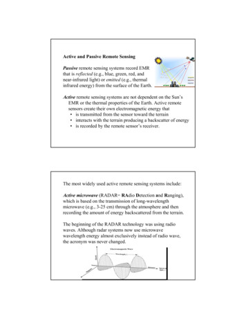
Remote Sensing, GIS and GPSChapter 3:This chapter briefly discusses the basics of various techniques, viz. the remote sensing,the digital image processing, visual Interpretation and delineation using GeographicalInformation System (GIS) domain3.1: Remote Sensing:“Remote sensing is defined as the science and art of obtaining information about anobject, area, or phenomenon through the analyses of data acquired by the sensor that isnot in direct contact with the target of investigation” (Schultz and Engman, 2000; Ritchieand Rango, 1996). This can be done by the use of either recording or real-time sensingdevice(s) mounted on aircraft, spacecraft, satellite, buoy, or ship. During last forty years,space travel has been giving humanity new opportunities, not only to peer into the depthsof the cosmos, but also to look at the length and breadth of our own world. Remotesensing enables us to acquire information about a phenomenon, object or surface while ata distance from it. More than just a source of pleasing pictures, these sophisticatedtechniques now allow scientists to understand the Earth in ways we never beforedreamed. From 1960 onwards, since the beginning of spaceflight, an ever growing bodyof information is being gathered using space-based remote sensing. Agriculture,meteorology, oceanography, ecology, cartography, botany, geomorphology and geologyare just a few of the disciplines which have been transformed by this technology. Some ofthe most important environmental issues of our time are only becoming understoodbecause of vast networks of remote sensing devices and data analysis systems. Inpractice, remote sensing is the stand-off collection through the use of a variety of devicesfor gathering information on a given object or area. The remote sensing is basically amulti-disciplinary science which includes a combination of various disciplines such as36
Remote Sensing, GIS and GPSoptics, spectroscopy, photography, computers, electronics and telecommunication, etc.All these technologies are integrated to act as one complete system in itself, known asRemote Sensing. In the decades to come, remote sensing will be a key tool for makingcritical decisions affecting the Earth and its resources.In a remote sensing system number of components work as links and each one isimportant for successful operation. They are listed below (figure 3.1).¾ Emission of electromagnetic radiation, or EMR¾ Transmission of energy from the source to the surface of the earth, interactionwith the atmosphere as well as absorption and scattering¾ Interaction of EMR with the earth’s surface: absorption, reflection and emission¾ Transmission of energy from the surface to the remote sensor¾ Sensor/detector data output¾ Data transmission, processing and analysisFigure 3.1: Different stages in Remote sensing and data acquisition(Source: http://www.ansp.org/museum/kye/tech environment/2001 remote sensing.php)37
Remote Sensing, GIS and GPS3.1.1: Basic components of Remote Sensing:The sun is the major source of energy, radiation and illumination. At any given momentour sun is bombarding the earth with a variety of wavelengths of EMR, including visiblelight, infrared, radio and microwaves. Detection and discrimination of surface featuresmeans detecting and recording of radiant energy reflected or emitted by surface (Joseph,2004; Lillesand and Kiefer, 1987; 2000). Different features return different amount andkind of energy in different bands of the electromagnetic spectrum, incident upon it. Thisunique property depends on the property of material (structural, chemical and physical),surface roughness, angle of incidence, intensity and wavelength of radiant energy (Elachi,1987). Everything in nature has its own unique distribution of reflected, emitted andabsorbed radiation. These spectral characteristics, if ingeniously exploited, can be used todistinguish one thing from another or to obtain information about shape, size and otherphysical and chemical properties. Because the emission and reflection of many differenttypes of EMR can be detected by instruments, they can also be used for remote sensing.Thus, to understand remote sensing, it is important to first understand the basics of EMR.3.1.1.1: Electromagnetic Radiation :Electromagnetic radiation is one of the fundamental forms of energy in the universe.EMR is a dynamic form of energy that propagates as wave motion at a velocity of light,i.e. C 3X10¹⁰ m/s. Electromagnetic energy radiates in accordance with the basic wavetheory. This theory describes the EM energy as traveling in a harmonic sinusoidal fashionat the velocity of light.Here, c vλ .3.1where, v is frequency, λ is wavelength and c is velocityAlthough many characteristics of EM energy are easily described by wave theory,38
Remote Sensing, GIS and GPSFigure 3.2: An electromagnetic wave. Includes electric wave(E) and magneticwave(M) at right angles, both perpendicular to the direction of propogation.(Source: index e.php)another theory known as particle theory offers insight into how electromagnetic energyinteracts with matter (figure 3.2). It suggests that EMR is composed of many discreteunits called photons/quanta. The energy of quantum is:Q h c/λ . .3.2where Q is the energy of quantum, h is plank’s constant39
Remote Sensing, GIS and GPSHence, from equation 3.1Q h cv.3.33.1.1.2: Electromagnetic SpectrumElectromagnetic energy is the energy source required to transmit information from thetarget to the sensor. It is a crucial medium that is described as an electromagneticspectrum. Many of the basic forms of energy in the universe are related as part of theelectromagnetic spectrum. On this spectrum, many forms exist that describe energy in aspecific region of the electromagnetic spectrum. These are visible light, radiowaves,microwaves, infra-red, uv rays, x-rays and gamma rays (figure 3.3).Fig 3.3: Electromagnetic spectrum(Source: http://hcgl.eng.ohio-state.edu/ ceg603/handouts/IntroRemoteSensing.pdf)40
Remote Sensing, GIS and GPSThis spectrum is an overview of the continuum of electromagnetic energy from extremelyshort wavelengths (cosmic gamma rays) to extremely long wavelengths (radio andtelevision waves). Note that as the wavelengths of energy decrease, the frequencyincreases. These divisions are not absolute and definite; overlapping may occur (table3.1).Table 3.1: Major regions of the electromagnetic spectrumRegion NameWavelengthComments 0.03 nanometersEntirely absorbed by the Earth's atmosphereand not available for remote sensing.X-ray0.03 to 30nanometersEntirely absorbed by the Earth's atmosphereand not available for remote sensing.Ultraviolet0.03 to 0.4micrometersWavelengths from 0.03 to 0.3 micrometersabsorbed by ozone in the Earth's atmosphere.PhotographicUltraviolet0.3 to 0.4micrometersAvailable for remote sensing the Earth. Can beimaged with photographic film.Visible0.4 to 0.7micrometersAvailable for remote sensing the Earth. Can beimaged with photographic film.Reflected Infrared0.7 to 3.0micrometersAvailable for remote sensing the Earth. NearInfrared 0.7 to 0.9 micrometers. Can be imagedwith photographic film.Thermal Infrared3.0 to 14micrometersMicrowave or Radar0.1 to 100centimetersGamma RayRadio 100 centimetersAvailable for remote sensing the Earth. Thiswavelength cannot be captured withphotographic film. Instead, sensors are used toimage this wavelength band.Longer wavelengths of this band can passthrough clouds, fog, and rain. Images using thisband can be made with sensors that activelyemit microwaves.Not normally used for remote sensing theEarth.(Source: tml)41
Remote Sensing, GIS and GPS3.1.1.3: Electromagnetic radiation quantities¾ Radiant energy (Q) is the energy carried by EMR. Radiant energy causes thedetector element of the sensor to respond to EMR in some appropriate manner.Unit of Radiant Energy Q is Joule.¾ Radiant Flux (Φ) (Phi) is the time rate of the flow of radiant energy. Unit ofRadiant flux is Joule/Second or Watt (W).¾ Irradiance (E) is the Radiant flux intercepted by a plane surface per unit area ofthe surface. It arrives at the surface from all directions within a hemisphere overthe surface. Unit of Irradiance E is W/m2 or Wm-2 (Watt per square meter).¾ Radiance (L) is defined as the radiant flux per unit solid angle leaving anextended source in a given direction per unit projected area of the source in thatdirection. The concept of radiance is intended to correspond to the concept ofbrightness. The projected area in a direction which makes an angle θ (Theta) withthe normal to the surface of area A is A cosθ. Unit for Radiance is Wm-2sr-1.¾ Spectral Reflectance (ρ(λ)) is the ratio of reflected energy to incident energy as afunction of wavelength.¾ Spectral Signature are the values of the spectral reflectance of objects averagedover different, well defined wavelength intervals comprise the spectral signatureof the objects or features by which they can be distinguished.42
Remote Sensing, GIS and GPS3.1.1.4: Interaction of EMR with atmosphere and earth surfaceThe sun is the source of radiation and electromagnetic radiation (EMR) from the sun thatis reflected by the earth and detected by the satellite or aircraft-borne sensor must passthrough the atmosphere twice, once on its journey from the sun to the earth and once afterbeing reflected by the surface of the earth back to the sensor. Interactions of the directsolar radiation and reflected radiation from the target with the atmospheric constituentsinterfere with the process of remote sensing and are called as “Atmospheric Effects”.The atmospheric constituents scatter and absorb the radiation, modify the radiationreflected from the target by attenuating it. Both scattering and absorption vary in theireffect from one part of the spectrum to the other. The solar energy is subjected tomodifications by several physical process as it passes the atmosphere, viz. scattering,absorption and refraction.¾ Atmospheric Scattering: Scattering is the redirection of EMR by particlessuspended in the atmosphere or by larger molecules of atmospheric gases or watervapor. The amount of scattering depends upon the size and abundance ofparticles, the wavelength of radiation and depth of the atmosphere through whichthe energy is traveling which varies both in time and over season thus scatteringwill be uneven spatially and will vary from time to time. Scattering reduces imagecontrast and changes spectral signature of ground objects as seen by the sensor.¾ Atmospheric Absorption: The gas molecules present in the atmosphere stronglyabsorb the EMR passing through the atmosphere in certain spectral bands. Mainlythree gases are responsible for most of the absorption of solar radiation, viz.ozone, carbon dioxide and water vapor. Absorption relatively reduces the amountof light that reaches our eye making the scene look relatively duller.¾ Atmospheric Windows: The atmosphere selectively transmits energy of certainwavelengths. The spectral bands for which the atmosphere is relatively43
Remote Sensing, GIS and GPStransparent are known as “Atmospheric Windows”. In the visible parttransmission is mainly effected by ozone absorption and by molecular scattering(figure 3.4).¾ Refraction: The phenomenon of refraction that is bending of light at the contactbetween two media also occurs in the atmosphere as the light passes through theatmospheric layers of varied clarity, humidity and temperature.Fig 3.4: Spectral characteristics of energy sources, atmospheric effects and sensingsystems wavelength scale are logarithmic.(Source: www.ucalgary.ca/GEOG/virtual/remoteintro.html)44
Remote Sensing, GIS and GPSRadiation from the sun, when incident upon the earth’s surface, is either reflected by thesurface, transmitted into the surface or absorbed and emitted by the surface. The EMR,on the interaction, experiences a number of changes in magnitude, direction, wavelength,polarization and phase. These changes are detected by the remote sensor and enable theinterpreter to obtain useful information about the object of interest. The remotely senseddata contain both spatial information (size, shape and orientation) and spectralinformation (tone, colour and spectral signature). The spectral band from 0.3 μm to 3 μmis known as the reflective region. In this band, the radiation sensed by the sensor is thatdue to the sun, reflected by the earth’s surface.¾ Reflection: Of all the interactions in the reflective region, surface reflections arethe most useful and revealing in remote sensing applications. Reflection occurswhen a ray of light is redirected as it strikes a non-transparent surface. Thereflection intensity depends on the surface refractive index, absorption coefficientand the angles of incidence and reflection.¾ Transmission: Transmission of radiation occurs when radiation passes through asubstance without significant attenuation. For a given thickness, or depth of asubstance, the ability of a medium to transmit energy is measured as transmittance(τ). τ transmitted radiation/incident radiation3.1.1.5: Data detection and output:The most important component of a remote sensing is the sensor/detector which, recordsthe variation of radiant energy reflected or emitted by objects or surface material.Different types of sensors are sensitive to different parts of the electromagnetic spectrum.The function of recording system is to convert the energy detected by sensor into a formwhich can be perceived. This is done by dividing the incoming energy by beam splittersand filters into different wavelength bands and then converting energy in each45
Remote Sensing, GIS and GPSwavelength band into electrical signal. The electrical signal is processed to giveradiometric data for each band, which is recorded in digital format.3.1.2: Remote Sensing Systems:The common remote sensing systems are of two types, Imaging (image forming) andNon-Imaging (nonimage forming). Image-forming systems are again of two types,framing type and scanning type. In scanning type, the information is acquiredsequentially from the surface in bits of picture elements or pixels, point by point and lineby line, which may be arranged after acquisition into a frame format.Remote sensing can be either passive or active. ACTIVE systems have their own sourceof energy such as RADAR, whereas the PASSIVE systems depend upon external sourceof illumination such as sun for remote sensing.3.1.2.1: Platforms and Sensors:The information flows from an object to a sensor in the form of radiation transmittedthrough the atmosphere. For a sensor to collect and record energy reflected or emittedfrom a target or surface, its must reside on a stable platform away from the target orsurface being observed. Based on its altitude above earth surface, platforms can beclassified as ground-borne, air-borne and space-borne.Space-borne platforms are in space, moving in their orbits around the earth. It is throughthese space-borne platforms, we get enormous amount of remote sensing data. Dependingon their altitude and orbit these platforms may be divided in two categories:¾ Geostationary satellites: An equatorial west to east satellite orbiting the earth atan altitude at which it makes one revolution in 24 hours, synchronous with theearth’s rotation, hence it gives continuous coverage over the same area day and46
Remote Sensing, GIS and GPSnight. These are mainly used for communication and meteorological applications,for e.g. the INSAT satellites.¾ Polar orbiting or Sun-synchronous satellites: A satellite with inclined northsouth orbit track westward at a rate such that it covers each area of the world at aconstant time of the day called the local sun time as the satellite moves from northto south. This ensures the similar illumination conditions while acquiring imageover a particular area over a series of days (figure 3.5). On the descending passfrom north to south the satellite travels on the sun lit side of the earth, while onascending pass from south to north it travels on the shadowed side of the earth.Through these satellites the entire globe is covered on regular basis and givesrepetitive coverage on periodic basis. All remote sensing resources satellites maybe grouped in this category for e.g. IRS series.Fig 3.5: Sunsynchronous satellites orbiting covery/Hurr ED Center/Satellites andSensors/Polar Orbits/Polar Orbits.html)47
Remote Sensing, GIS and GPSSensor is the device that gathers energy (EMR or others), converts it into a signal andpresents it in a form suitable for obtaining information about the target underinvestigation. Sensors used for remote sensing can be broadly classified as thoseoperating in Optical Infrared (OIR) region and those operating in microwave region. OIRand microwave sensors can further be subdivided into passive and active depending onthe source of energy.¾ Active sensors use their own source of energy to illuminate earth surface and apart of it is reflected and received to gather information.¾ Passive sensors do not have their own source of energy but instead receive solarelectromagnetic energy reflected from surface or energy emitted from surfaceitself hence it can not be used at night time, except thermal sensors. Energy that isnaturally emitted (e.g. Thermal energy) can be detected day or night, as long asthe amount of energy is large enough to be recorded (Sabins, 1997).3.1.3: Types of Remote Sensing:Remote sensing can be broadly classified into three types with respect to the wavelengthregion and type of sensor involved for data acquisition; viz. Optical (Visible andReflective Infrared), Thermal Infrared and Microwave. In present study optical remotesensing technique has been used to achieve the defined objectives.3.1.3.1: Optical Remote Sensing:Optical remote sensing involves the use of visible part of the EM spectrum. Energyemitted from sun is used for visible and reflective infrared remote sensing. TheInternational Commission on Illumination has defined the visible spectrum to be from0.38 to 0.79 μm. The human eye has its peak sensitivity at 0.55 microns, which is48
Remote Sensing, GIS and GPSapproximately the peak of the emission curve of the sun (Jensen, 1996; Sabins, 1997;Gupta, 1999; 2003). Remote sensing data obtained in the visible and reflective infraredregions mainly depends on the reflectance of objects on the ground surface. Therefore,information about objects can be obtained from the spectral reflectance (Elachi, 1987).3.1.3.2: Thermal Infrared Remote Sensing:The source of radiant energy used in thermal infrared remote sensing is the object itself,because any object with a normal temperature will emit EM radiation with a peak atabout 10 μm (Sabins, 1997; Gupta, 2003).3.1.3.3: Microwave Remote Sensing:In microwave region, there are two types of microwave remote sensing, passive andactive. In passive microwave remote sensing, the microwave radiation emitted from anobject is detected, while in active microwave remote sensing, source of EM radiationsand detector are placed on the sensor (Elachi, 1988).3.1.4 Inherent characteristics and spectral signature of objectsIn any photographic image forming process, the negative is composed of tiny silverdeposits formed by the action light on photosensitive film during exposure. The amountof light received by the various sections of the film depends on the reflection of EMRfrom various objects. The light, after passing through the optical system, gives rise todifferent tones and textures.49
Remote Sensing, GIS and GPSIn visual interpretation, an interpreted is primarily concerned with recognizing changes intonal values, thereby differentiating an object of a certain reflective characteristic fromanother. However, he must be aware that the same object under different moisture orillumination conditions and depending on the wavelength of incident energy, may reflecta different amount of light. For this reason, a general key, based on tone characteristics ofobjects, cannot be prepared. In such cases, other characteristics of objects such as theirshape, size and pattern, etc., help in their recognition.Spectral signature is the parameter which determines the character of the object underobservation. This can be defined as a unique pattern of wavelengths radiated/reflected byan object. It can be categorized as:¾ Spectral variation: Variation in reflectivity and emissivity as a function ofwavelength.¾ Spatial variation: Variation in reflectivity and emissivity with spatial position(i.e. shape, texture and size of the object).¾ Temporal variation: Variation of emissivity and reflectivity like that in diurnaland seasonal cycle.¾ Polarization variation: Variations are introduced by the material in the radiationreflected or emitted by it.Each of these four features of EMR may be interdependent. A measure of these variationsand correlating them with the known features of an object provides signature of the objectconcerned. The knowledge of the state of polarization of the reflected radiation inaddition to spectral signature of various objects in remote sensing adds dimension for50
Remote Sensing, GIS and GPSanalysis and interpretation of remote sensing data. These parameters are extremely usefulin providing valuable data for discriminating the objects.3.1.5: Elements of image interpretationRecognizing targets is the key to interpretation and information extraction. Observing thedifferences between targets and their backgrounds involves comparing different targetsbased on any, or all, of the visual elements of tone, shape, size, pattern, texture, shadow,and association. Identifying targets in remotely sensed images based on these visualelements allows us to further interpret and analyze. The nature of each of theseinterpretation elements is described below:3.1.5.1: Tone refers to the relative brightness or colour of objects in an image.Generally, tone is the fundamental element for distinguishing between different targets orfeatures. Variations in tone also allow the elements of shape, texture, and pattern ofobjects to be distinguished.3.1.5.2: Shape refers to the general form, structure, or outline of individual objects.Shape can be a very distinctive clue for interpretation. Straight edge shapes typicallyrepresent urban or agricultural targets, while natural features are generally more irregularin shape.3.1.5.3: Size of objects in an image is a function of scale. It is important to assess thesize of a target relative to other objects in a scene, as well as the absolute size, to aid in51
Remote Sensing, GIS and GPSthe interpretation of that target. A quick approximation of target size can directinterpretation to an appropriate result more quickly.3.1.5.4: Pattern refers to the spatial arrangement of visibly discernible objects.Typically an orderly repetition of similar tones and textures will produce a distinctive andultimately recognizable pattern.3.1.5.5: Texture refers to the arrangement and frequency of tonal variation inparticular areas of an image. Rough textures would consist of a mottled tone where thegrey levels change abruptly in a small area, whereas smooth textures would have verylittle tonal variation.3.1.5.6: Shadow is also helpful in interpretation as it may provide an idea of theprofile and relative height of a target or targets which may make identification easier.However, shadows can also reduce or eliminate interpretation in their area of influence,since targets within shadows are much less (or not at all) discernible from theirsurroundings.3.1.5.7: Association takes into account the relationship between other recognizableobjects or features in proximity to the target of interest. The identification of features thatone would expect to associate with other features may provide information to facilitateidentification.52
Remote Sensing, GIS and GPS3.1.6: Spectral behavior of surface featuresAs EMR incidents on earth’s surface, behavior of land features is mainly due to thecomponent of the target at that locality. Since each of these components exhibit typicalspectral signature influenced by so many other parameters of their own, they are to beconsidered separately to understand the nature of EMR interaction with each components.Spectral signature or water, vegetation and soil are discussed below (figure 3.6):Fig 3.6: Typical spectral reflectance curves for vegetation (two different types), soil(two different types) and water (two different types)(source: /intro2c.htm)53
Remote Sensing, GIS and GPS3.1.6.1: Spectral reflectance and signature of soilThe majority of the flux incident on a soil surface is reflected or absorbed and little istransmitted. The reflectance properties of the majority of soils are similar, with a positiverelationship between reflectance and wavelength, as seen in fig: 3.7. Main factorsinfluence the soil reflectance in remote sensing images are mineral composition, moisturecontent, organic matter content and soil texture (surface), soil structure and iron oxidecontent. Size and shape of the soil aggregate also influence the reflectance in the images.3.1.6.1.1: Effect of mineral composition:The mineral composition of soils affects the reflectance spectrum. Increasing reflectanceof soils occurs from the visible to the shortwave infrared - with absorption bands around1.4 µm and 1.9 µm related to the amount of moisture in the soil.3.1.6.1.2: Effect of soil texture, structure and moisture:The relationship between texture, structure and soil moisture can best be described withreference to two contrasting soil types. A clay soil tends to have strong structure, whichleads to rough surface texture, and have high moisture content and as a result have afairly low diffuse reflectance. In contrast, a sandy soil tends to have a weak structure,which leads to a smooth surface texture, and have low moisture content and as a resulthave fairly high and often specular reflectance properties. Soil texture (roughness) alsoaffects soil optical properties. In visible wavelengths the presence of soil moistureconsiderably reduces the surface reflectance of soil, until the soil is saturated. Reflectancein near and middle infrared wavelengths is also negatively related to soil moisture. Anincrease in soil moisture will result in a rapid decrease in reflectance in water andhydroxyl absorbing wavebands. The effect of water and hydroxyl absorption is morenoticeable in clay soil as it has much bound water and very strong hydroxyl absorptionproperties.54
Remote Sensing, GIS and GPSFig 3.7: effect of soil moisture on soil spectral reflectance(Source: Tutorials from Indian Institute of Remote Sensing, Dehradun, India)3.1.6.1.3: Effect of organic matter:Organic matter may indirectly affect the spectral influence, based on the soil structureand water retention capacity. It is dark and its presence decreases the reflectance from thesoil up to an organic matter content of around 4-5% but beyond it hardly effects.3.1.6.1.4: Effect of iron oxide:Iron oxide gives many soils their rusty red coloration. Iron oxide selectively reflects redlight.55
Remote Sensing, GIS and GPS3.1.6.1.5: Effect of size and shape:Soil aggregate size and shape influence the reflectance properties. If the size of a soilaggregate large in diameter, a decrease in reflection will result.3.1.6.2: Spectral reflectance and signature of vegetationComponents that are involved in classifying vegetation from remote sensing imagesreceived from satellites include chemical properties and physical properties recorded forthe vegetation (including surface texture, roughness and local slope properties).There are several factors that influence the reflectance quality of vegetation on satelliteand remote sensing images. These include brightness, greenness and moisture. Brightnessis calculated as a weighted sum of all the bands and is defined in the direction ofprincipal variation in soil reflectance. Greenness is orthogonal to brightness and is acontrast between the near-infrared and visible bands. It is related to the amount of greenvegetation in the scene. Moisture in vegetation will reflect more energy than dryvegetation.Leaf properties that influence the leaf optical properties are the internal or externalstructure, age, water status, mineral stresses, and the health of the leaf (figure 3.8). It isimportant to note that the reflectances of the optical properties of leaves are the same,regardless of the species. What may differ for each leaf, is the typical spectral featuresrecorded for the three main optical spectral domains; leaf pigments, cell structure andwater content.56
Remote Sensing, GIS and GPSFig 3.8: Typical spectral response characteristics of green vegetation(Source: http://www.rsunt.geo.ucsb.edu/rscc/vol2/lec2/2 2.html#21)Electromagnetic wavelengths affect different parts of plant and trees. These parts includeleaves, stems, stalks and limbs of the plants and trees. The length of the wavelengths alsoplays a role in the amount of reflection that occurs. Tree leaves and crop canopies reflectmore in the shorter radar wavelengths, while tree trunks and limbs reflect more in thelonger wavelengths. The density of the tree or plant canopy will affect the scattering ofthe wavelengths.Within the electromagnetic spectrum, bands will produce different levels of reflectancerates. For example, in the visible bands (400 - 700 nm), a lower reflectance will occur asmore light will be absorbed by the leaf pigments
Remote Sensing, GIS and GPS 38 3.1.1: Basic components of Remote Sensing: The sun is the major source of energy, radiation and illumination. At any given moment our sun is bombarding the earth with a variety of wavelengths of EMR, including visible light, infrared, radio and microwaves. Detection and discrimination of surface features