Transcription
University of WollongongResearch OnlineFaculty of Engineering - Papers (Archive)Faculty of Engineering and Information Sciences2008Harmonic allocation using IEC/TR 61000-3-6 atthe distribution/transmission interfaceVictor GosbellUniversity of Wollongong, vgosbell@uow.edu.auSarath PereraUniversity of Wollongong, sarath@uow.edu.auTimothy BrowneArizona State cation DetailsV. J. Gosbell, T. J. Browne & S. Perera, "Harmonic allocation using IEC/TR 61000-3-6 at the distribution/transmission interface," inICHQP 2008: 13th International Conference on Harmonics & Quality of Power, 2008, p. [6].Research Online is the open access institutional repository for the University of Wollongong. For further information contact the UOW Library:research-pubs@uow.edu.au
1Harmonic Allocation Using IEC/TR 61000-3-6at the Distribution/Transmission InterfaceV. J. Gosbell, Member, IEEE, T. J. Browne, Member, IEEE, S. Perera, Member, IEEEAbstract-- IEC Technical Report 61000-3-6 gives principles tobe applied to ensure acceptable harmonic levels in powersystems. Detailed analysis methods have been developed to applythese principles to both distribution and transmission systems. Atthe transmission/distribution interface, it is found thattransmission harmonic allocations can be as little as one third ofthe allocation which would be given to an equivalent distributionload. Possible adverse consequences are discussed and severalmodifications to avoid this mismatch are given. Therecommended modification is a hybrid approach combiningaspects of both the distribution and transmission allocationmethods.Index Terms—distributionstandards, transmission systems.systems,harmonics,IECI. seScritSiSmaxStUhUSZh1ZhiαMeaningBulk Supply PointHarmonic current at pcc allocated to installation SiHarmonic voltage at pcc allocated to installation SiFault level at pcc of installation SiHarmonic voltage available for loads connected to MV busHarmonic orderhth harmonic allocation constantHV planning level for hth harmonicMV planning level for hth harmonicBase MVAMaximum load to be given an unmodified distributionallocationMaximum demand of installation being consideredMaximum distorting load which would be considered forconnection to a transmission system in its present stateMV system MV load supply capabilityhth harmonic voltage componentUpstreamFundamental impedance at pcc for load Sihth harmonic impedance at pcc for load SiSummation law exponentThe IEC have developed a set of guidelines to help utilitieskeep harmonics under control. The most important at MVlevels and above is IEC/TR 61000-3-6 [1] which coverscompatibility levels, planning levels, and methods formanaging the connection of large disturbing customers. Theprocedures are fairly straightforward when applied to strongdistribution systems, but are less clear regarding distributionsystems with long feeders and transmission systems.Work has been performed in Australia in developing adetailed approach, consistent with IEC principles, to thesetypes of system [2], [3]. Different approaches are needed tothe distribution and transmission systems: the first can bebroken down into independent, small and relatively timeinvariant subsystems, while the transmission system needs tobe studied holistically, is continually evolving, andconsequently is difficult to model reliably.The paper will summarise IEC harmonic allocationprinciples and the developed methods for distribution andtransmission harmonic allocation. Both approaches will beapplied to a test case which will highlight a difference in theallocation strategies by a much as three to one. There is thus arisk that a distribution bulk supply point can be loaded by thedistributor's allocation policies to a point that threatens thetransmission company's ability to manage harmonics. Thepaper will discuss the factors that lead to this situation andsuggest methods for resolving the difficulty.III. SUMMARY OF IEC/TR 61000-3-6 PRINCIPLESReference [1] specifies the principles which can be used forthe harmonic management of distribution and transmissionsystems. Time-varying harmonics are specified by their 95%probability values. The details of measurement and statisticalanalysis are given in IEC 61000-4-7 [4]. Diversity betweenharmonic sources is represented by the Summation LawαDII. INTRODUCTIONEVELOMENTS in technology and new consumerproducts are affecting the type of equipment connected tothe power system. Modern equipment increasingly drawscurrent distorted current waveforms with significant harmoniccontent. This modifies the voltage waveform and utilities mayfind it increasingly difficult to meet harmonic standards.V. J. Gosbell and S. Perera are with the University of Wollongong (e-mail:v.gosbell@uow.edu.au and sarath@uow.edu.au).T. J. Browne is with Arizona State University (email: tbrowne@ieee.org).978-1-4244-1770-4/08/ 25.00 2008 IEEEU h Σi U hiα(1)where α is chosen according to the harmonic order with avalue of α 1.4 for harmonics in the range 5 h 10 and avalue of 2 for higher order ones.Compatibility levels are given as a reference for the settingof equipment immunity (immunity levels must be more thanthe compatibility level) and utility emission (planning levels must be less than the compatibility level). Since the flow ofharmonic current in general is from the LV part of the powersystem to the HV transmission system and then intogenerators, the harmonic profile of a typical power system
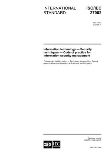
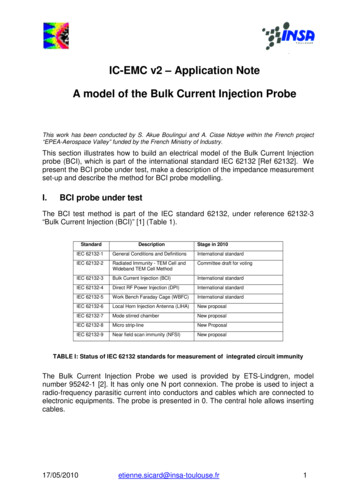
2shows the highest voltages at LV, reducing through the MVsystem to the HV system. To assist with allocating harmonicloads to different voltage levels, the planning levels are gradedfrom higher values at LV to the smallest values at HV/EHV[1]. An extract from the values adopted at present forAustralia is given in Table I [2].TABLE ISELECTION OF PLANNING LEVELS (% OF NOMINAL) USED IN AUSTRALIAVoltage tallations are assessed in 3 stages. The most significantpart of [1] for most utilities is Stage 2, the determination of aharmonic current allocation for a specific installation, and thiswill be the focus of the present paper. Reference [1] is not aninternational standard – despite some local versions having theforce of a standard – but a Technical Report. It containsprinciples and some suggested analysis methods, but is not acomplete detailed guide for utility analysis. Two generalallocation principles are given(i). The harmonic allocation increases with maximumdemand (called "agreed power" in the standard).(ii). All customers, both present and future, have the rightto a share of the harmonic allocation. The allocationshall be such, that when each customer is just drawingtheir full allowance, the maximum harmonic voltagejust reaches the planning level.IV. DISTRIBUTION SYSTEM HARMONIC ALLOCATIONReference [1] details the allocation of harmonic current toinstallations connected to strong distribution systems.Distribution systems generally have the following generalfeatures radial topology can be broken down into subsystems supplied from asubstation which have weak interactions with otherparts of the system major loads and impedances generally well known line capacitance not important little change over the period covered by a harmonicstudyThe principles of distribution allocation are discussedrelative to the system illustrated in Fig.1.USMVS1S2SnFig. 1. Distribution system showing MV subsystem and upstream supplyIt is assumed that the upstream system US, which may beHV or a higher level MV system, has reached its planninglevel LhUS and can be represented by a harmonic source of thismagnitude. Since the MV system is limited to its planninglevel LhMV, the voltage available for the total MV load St is,making use of (1),ααG hMV L hMV L hUSα(2)The effects of transfer coefficient and LV loads are ignoredin this discussion to simplify the presentation. EUhi is theharmonic voltage emission for load Si which can bedetermined, again making use of the diversity equation (1) as1/αE Uhi (S i / S t ) G hMV(3)The corresponding harmonic current emission isE Ihi E Uhi / Z hi(4)where Zhi is the harmonic impedance at the point ofconnection of load Si. For distribution systems withoutcapacitor resonance, this can be well approximated by h timesthe fundamental short-circuit reactance. Where the distributionsystem has short feeders, Zhi will be relatively small. If all theloads at the supply point take their full allocation, it is possiblethat the supply harmonic current will be very large.Determination of GhMV requires differentiation across MVplanning levels where one MV system supplies another.Reference [1] only gives one suggested value for all MVlevels. One of the purposes of [2] was to suggest adifferentiation and this is shown in Table I giving one valuefor 33kV levels and another for 11kV/22kV.V. TRANSMISSION SYSTEM HARMONIC ALLOCATIONStage 2 allocation for transmission system has beenundertaken by the authors and reported in [3]. It is morecomplex and less precise than distribution harmonic allocationbecause of the following factors Meshed configuration causes greater interaction difficult to break up into non-interacting subsystems needs to be studied as a single system Line capacitance significant, causing resonances inharmonic impedances and the influence of a load onremote nodes Always changing because of varying generatorallocations and at a slower timescale the switching oflines, transformers etc, load variationsBecause of the continuous changes, it is useful to someextent to think of the system for modelling purposes asundergoing a transition through a number of fixed parameterscenarios. The difficulties caused by these scenarios cannot beexaggerated. Although any one scenario can be modelled,choosing the scenarios to be modelled is very difficult. Once aset of scenarios has been chosen, it is also necessary to decidethe proportion of time that each scenario holds. Linecapacitance can mean that a slight change in scenario gives amajor change in system behaviour because of a sharpresonance. The assumption in [1] that all loads deserveharmonic current leads to their representation as harmoniccurrent sources for these studies. This assumption increasesthe chance of analysis giving sharp resonances since itremoves the possibility of load damping from the computer
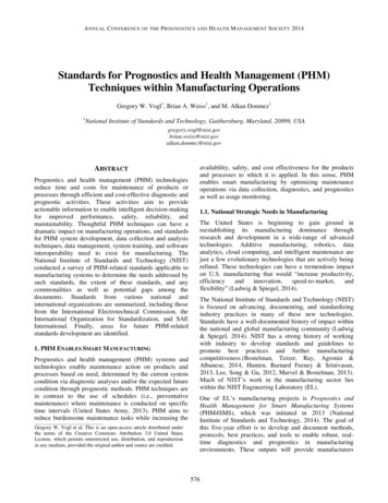
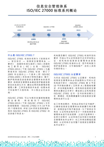
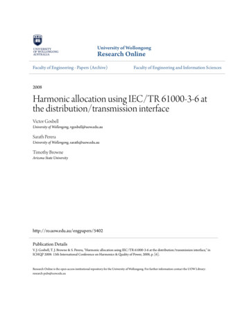
3model.As a result of these uncertainties, complex computerstudies do not allow precise allocation studies to be made. It isinevitable that simplifying assumptions have to be madegiving uncertainty, so a greater safety margin has to be builtinto transmission allocation compared with distributionallocation. It appears to be inevitable that the transmissionsystem cannot be as fully utilised for harmonic absorption asmuch as the distribution system.We now give a summary of the transmission allocationmethod proposed in [3]. The approach is based on theallocation of harmonic voltage to each load in the transmissionsystem based onEUhi khS1/α(5)where kh is the allocation constant. The exponent termallows for diversity - that is to give more harmonic current,relative to rating, for smaller loads. A load Si is then given thesame allocation whether the allocation is made to the whole orto the parts and then combined.Reference [3] shows that it is difficult to determine kh withconfidence based on modelling several system scenarios. Asimpler approach is to consider the maximum load Smax in thetransmission system. One can have more confidence that itwill give the largest contribution to the harmonic voltage at itspoint of connection than for lesser loads. It is assumed that itgives a harmonic voltage of 50% of the planning level, giving0.5LhHV khSmax1/α(6)from which the allocation constant can be determined. Theequation is to be applied at all nodes and can be used forpresent loads or future ones. The calculated valued of kh canbe used until the transmission system has an upgradesufficient that a larger value of Smax can be considered.Note the degree of conservatism in the assumption of 50%of the planning level to the local load. Because of diversity,the remote loads can take up more than half the planninglevel, equal to (1 - 0.5α)(1/α) 70% for α 1.4 and 87% athigher harmonics where α 2.The voltage allocation EUhi has no immediate meaning to acustomer who would have a much greater appreciation for aharmonic current allocation. There is thus need to estimate theharmonic impedance at the connection point for the load Si.For a fixed scenario, this impedance varies in a complexmanner with frequency because of the resonance of linecapacitance with additional complexity due to lumpedcapacitors and the neglect of load damping. With a reasonablenumber of scenarios, there is a large rang of values for theharmonic impedance at a point and it is important to make apessimistic choice of the larger values. Reference [1] showsthat, for the lower frequencies, the value given in (7) is a goodestimate of the upper bound of Zhi:Zhi.max 2hZ1(7)where Z1 is the fundamental value obtained from fault levelconsiderations. Hence the allocated current should be(8)EIhi EUhi/Zhi.maxVI. HARMONIC CURRENT ALLOCATION AT THETRANSMISSION/DISTRIBUTION INTERFACEFig. 2 shows part of a transmission system with a largeinstallation S1 and a distribution bulk supply point with ratingS2.large installation S1 - Ih isallocated by transmissioncompanyBSP S2 - Ih is determined bydistributor allocation policiesFig.2. Transmission system with large installation S1 and distribution bulksupply point S2The allocation to S1 will be based on transmissionconsiderations. In many situations, the transmission companywill have no agreement regarding harmonic voltages handeddownstream to the distributor or harmonic currents which arepassed upstream from distributor to transmission company.The harmonic current drawn by S2 will be the result ofdistribution allocation procedures being applied to all theloads supplied by S2. If S2 supplies only a few large loads allconnected close to the secondary busbar of S2, it is possiblethat this current could be larger than what S2 would receive asa transmission load. This could lead to the situation where thetransmission company is unable to meet its planning levels atsome connection points. This could lead to damage to nearbycustomers such as S1, especially if there are passive filtersconnected with small safety margins, or to a breach of contractwhere the transmission company has given an obligation tomeet its harmonic planning levels. To check for thispossibility, the two allocation processes will be applied to acase study selected to be typical of Australian conditions.To investigate the worst case scenario, Fig. 3 shows anexample bulk supply point where all the load may beconsidered as a single installation concentrated at thesecondary MV busbar.HVMVSingleinstallation SiTransmissionsystemDistributionsystemFig.3. Example systemRepresentative parameter values are given in Table II.TABLE IIPARAMETER VALUES FOR THE SYSTEM OF FIG.3ParameterValueSmaxSiFault level at HV busFault level at MV bus1,000 MVA300 MVA3,000 MVA1,000 MVAParameterhαLhHV.LhMV.Value51.42%3.1%
4Appendix A shows the different 5th harmonic currentswhich would be allocated to the installation Si of maximumdemand 300MVA depending on whether it be considered adistribution load with connection point at the MV busbar or atransmission load with connection point at the HV busbar. Asa distribution connected load it would be allocated 1.2%relative harmonic current, while as a transmission connectedload it would be allocated one third of this or 0.4% relativeharmonic current.A large customer emitting a current 3 times higher than isallocated under the proposed transmission allocation methodcan in some situations cause transmission harmonic voltagesto exceed planning levels. The conditions needed would be Significant proportion of transmission customerstaking their full harmonic current allocation Close coupling between the customer pcc and someother nodes in the transmission system where there isa high harmonic loading.Hence the discrepancy between the two allocationapproaches is expected to lead occasionally to high harmoniclevels in the transmission system and it is worth attempting tounderstand why the discrepancy occurs and how to remove it.The reason for the disparity is the different modellingapproaches used with transmission and distribution systems.Distribution systems have reasonably well definedcharacteristics at harmonic frequencies (providing there are nouncompensated capacitors influencing the system) and it ispossible to allocate harmonic currents with only a small safetymargin. Transmission system harmonic characteristics are lesscertain. As a result, a large safety factor has to be allowed intransmission system harmonic allocation. A factor of about 4comes about because of A factor of 2 to allow for uncertainty in the systemharmonic resonance at the pcc A factor of 2 to allow for the contributions of remoteloads at the pcc.It might be asked why this problem has not been reportedelsewhere. For the problem to become apparent, it wouldrequire every load supplied by a Bulk Supply Point (or somesimilar substation supplied from EHV-HV) to be very close tothe supply terminals so that a reasonable harmonic voltageallocation becomes converted to a high harmonic currentallocation. This is unlikely if the BSP supplies a normaldistribution system having the majority of loads fed throughseveral zone substations. It is unlikely that every load is closeto the zone substation supply terminals and it is also unlikelythat every load is taking its full harmonic allocation. The mostlikely scenario for the voltage level mismatch problem to ariseis at a BSP with one or two major loads taking up most of thesupply capacity and connected right at the BSP supplyterminals.Transmission systems are reported as having harmonicvoltages higher than planning levels at some connection pointsat some frequencies, but insufficient is reported to know if it isbecause of the mismatch problem or because of somecustomer exceeding their harmonic allocation. For example[5] reports the result of a survey of 70/150kV sites. Harmonicplanning levels are exceeded at some sites for some harmonicsin the range 11-37 but there have been no reports ofinterference. Another [6] reports a harmonic survey of 28substations in a 69/315kV transmission system. Planninglevels were exceeded at some sites at the 5th, 11th, 23rd, 25th,35th and 37th harmonics.In both cases, no adverse effects were reported. This isbecause the main reason for EHV-HV planning levels is toensure that LV compatibility levels are not exceeded at LV.Harmonic levels here depend to some extent on transmissionsystem levels, but more importantly on the harmonic emissionof loads in the local distribution system.VII. MODIFICATION TO THE ALLOCATION PROCESS TO REMOVETHE DISCREPANCYThree approaches of increasing complexity are examinedfor removing the allocation discrepancy. In the first, amaximum value is applied to the harmonic current allocationin situations where high transmission harmonic voltages mightarise. The Hybrid allocation approach breaks large loads upinto two parts, one part of which is treated as distributionconnected and the other part as transmission connected. Theadjustment of planning levels is examined since their selectionis considered to be the root cause of the allocationdiscrepancy.A. Capped harmonic allocationFor every harmonic allocation in a distribution system, onewould need to consider the equivalent allowable transmissionsystem absorption at the supply point and apply this as a cap.It would be convenient if a simple test could be developed thatwould guide when capping need to be applied. It may requireexperience with several cases in which the allocationdiscrepancy is a serious concern before such a test could bereliably developed. For this reason, this approach is notconsidered further here.B. Hybrid harmonic allocationThe proposed solution is to try to find a simple rule-ofthumb which would identify when a problem is likely to occurand introduce a modification to the allocation procedure forthis case. We consider only large loads which are connectedone level down from the transmission system. We define avalue Sscrit, the maximum such load which is to be given anunmodified distribution system harmonic allocation.Appendix B.A suggests that a value might be 5% of themaximum MVA which is would be connected directly to thetransmission system. For loads Si greater than Scrit, a two partharmonic allocation is given The part Scrit is given an allocation by a distributionapproach. The part (Si – Scrit) is given an allocation by atransmission approach The two parts are combined using the SummationLaw
5Appendix B.B gives detailed equations for applying thisapproach.The strategy of giving a straight transmission approach toall loads greater than Scrit was also considered. This requiresless calculation then the above method and appears attractiveat first. However, consider loads S1, just less than Scrit andload S2 just greater than Scrit. With this strategy, S2 wouldreceive as little as 1/3 of what was allocated to S1, even whenit was only slightly larger. This anomaly is removed by thetwo part allocation scheme recommended.The proposed approach has been applied to the examplediscussed in Section VI.A, where a 300MVA load wasallocated 1.2% harmonic current by distribution principles and0.4% harmonic current by transmission principles. In the newapproach, detailed in Appendix B.B, with Smax 1,000 MVAand Scrit taken as 50MVA, the load would be allocated 0.6%harmonic current.In cases where this modified allocation may give problemsto the customer, it can be given more for a temporary periodunder a transmission system Stage 3 allocation policy. Thisshould involve a pre-connection and post-connectionharmonic monitoring campaign.C. Adjusted planning levelsThe distribution of harmonic allocation between thedifferent voltage levels depends on the profile of the planninglevels from EHV-HV down to MV and LV. A fundamentalapproach is to adjust the planning levels to allow lessharmonic current in the distribution system and more in thetransmission system. This would mean increasing the planninglevels at the higher voltage levels. This may be a good longterm solution, but it probably requires an extensive study ofthe original IEC methodology before a recommendation canbe given which has no other adverse side-effects.Some insight can be gained by applying this idea to theexample of Fig. 3. The transmission allocation is directlyaffected by the HV planning level of 2% (A.2 Step 1). Thedistribution allocation is affected by the more complexexpression involving both HV and MV planning levels:α3.1α 2 α (A.1 Step 1). The ratio of the present allocationsαis determined by the ratio 3.1α 2 α /2 and is three timeslarger than desirable. Suppose we keep the MV planning levelconstant at 3.1% and change the HV planning level from itspresent value of 2% to LhHV.new. We then need to solveα3.1α L hHV.newαααα 1 3.1 2(9) L hHV.new2 3 from which LhHV.new 2.75%, rather higher than the present2%. It is worth noting that there are several papers which statethat their harmonic voltages are larger than the presentplanning levels with no apparent harm [5], [6] and an increasein HV planning levels would appear to be welcomed.We now investigate how these new planning levels wouldaffect harmonic allocation. The increase in HV allocationwould be in the ratio of 2.75 to 2 or 138%. The reduction inMV allocation is to a value 46% of the old. New planninglevels based on this idea would reduce MV allocations morethan the increase in transmission allocation, so the netharmonic absorption of the power system would be reducedfor the benefit of better control over transmission systemharmonic levels.VIII. CONCLUSIONSIt has been shown how the principles of [1] can be appliedto both distribution and transmission systems. The differentnature of the two types of systems means the adoption ofsomewhat different allocation methodologies, with greatercertainty and less need for a safety margin for distributionsystems. As a result, there is a discrepancy between the twoallocation methods which is highlighted at thetransmission/distribution interface. The discrepancy is infavour of the distribution system and there is a risk oftransmission harmonic levels being exceeded as aconsequence.Three methods of resolving the discrepancy are discussed.The one which seems to offer a simple solution is a hybridallocation approach applied to loads of sufficiently large size.A more fundamental approach is a review of planning levels.This will lead to a reduction in the overall harmonicabsorption of power systems, and should only be pursued ifthe allocation discrepancy is found to be widespread with thepresent values.IX. APPENDIX A – DETAILED CALCULATION OF ALLOCATIONRefer to Fig. 3 and Table II for the system under study andits parameters.A. Distribution system allocationChoose a base Sbase 100 MVA1. Determine GMV.h, the harmonic voltage available for loadsconnected to the MV systemαααG MV.h L MV.h L HV.h 1.4 3.11.4 2.01.4 1.78%In this case, this is all allocated to Si. HenceEUhi 1.78%2. Determine the harmonic impedance as seen from the MVsystemZ1i Sbase/FLMV 100/1,000 0.1 puZ5i hZ1i 5 0.1 0.5 pu3. Find the harmonic current to be allocated to load SiEIhi EUhi/Zhi 1.78/0.5 3.56% (100 MVA base) or 1.19%B. Transmission system allocationChoose a base Sbase 100 MVA, giving Smax 10 pu andSi 3 pu.1. Determine the harmonic allocation constant khkh 0.5LHV.h/Smax1/α 0.5 2%/101/1.4 0.00192. Determine the harmonic voltage to be allocated to load SiEUhi khSi1/α 0.0019 31/1.4 0.42%3. Estimate the maximum value of the harmonic impedance atthe pcc for load Si.Z1i Sbase/FLi 100/3000 0.033 puZhi.max 2hZ1i 2 5 0.033 0.333 pu
64. Find the harmonic current to be allocated to load SiEIhi EUhi/Zhi.max 0.42%/0.333 1.26% (100 MVAbase) or 0.42%In this case, we see that the load has a harmonic currentallocated to it on the distribution side of almost three timeswhat it would be allocated from the transmission side.X. APPENDIX B – HYBRID ALLOCATION METHODB. Allocation scheme for large loads connected to distributionsystemsSuppose the critical value of load is Scrit. The proposedallocation strategy to overcome voltage level mismatch is toallocate by distribution principles to loads less than Scrit and toallocate to loads more than this by transmission principles. Asexplained in Section V, this has to be implemented by a twopart approach, breaking a load up into parts Scrit and Si – Scrit.Suppose, for Si, we have allocated harmonic currents Ihi.dand Ihi.t by distribution and transmission approachesrespectively. The distribution allocation to Scrit can be foundby proportion, allowing for diversity by the Summation Law.1/αIh.crit.d (S crit / S i ) I hi.d(B.1)Hence the two components of current allocated to Si are,for the Scrit part of itIhi1 Ih.crit.d(B.2)For the remainder of it Si – Scrit, using proportion and theSummation Law1/α(B.3)Ihi2 ((S i S crit ) / S i ) I hi.tThe allocated harmonic current is found by combining(B.2) and (B.3) with a diversity allowanceαααααI hi I hi1 I hi2 (S crit / S i )I hi.d ((S i S crit ) / S i )I hi.tαIhi (I hi.t (S crit / S i ) I hi.d I hi.tααα)C. Example of allocation to large loadIn the previous example, for Si 300MVA, Ihi.d 1.2% andIhi.t 0.4%. Assuming Smax 1,000 MVA, Scrit 5% of Smax or50 MVA.αA. Minimum load Scrit to be given by distribution allocationIn the example, it was found that a single load of 300MVAwas allocated a harmonic current about 3 times more thansuch a load deserved from transmission considerations.Suppose that this load was reduced, and the rest of the loadhad negligible distortion. How small would the load Si have tobe in order for the distribution allocation to be acceptable tothe transmission system? If there was no diversity, we wouldhave to solve(Si/300) 0.33Because of diversity, instead we have to solve(Si/300)1/α 0.33Setting α to 1.4 (valid for harmonics in the range 5-10) givesSi 63 MVABased on this rough calculation, it is recommended that Scritis taken as 5% of the maximum transmission load (giving50MVA in this case). Loads greater than Scrit and connected tothe distribution system will need to be given a modifiedharmonic allocation procedure.givingSi Scrit, giving Ihi.d, a simple distribution allocation asrequired. We also note that, in the limit for large Si, theexpression approaches Ihi.t, again as required.(B.4)To check that this law gives the right effect, we substituteIhi (I hi.t (S crit / S i ) I hi.d I hi.tααα) 0.6%XI. REFERENCES[1][2][3][4][5][6]International Electrotechnical Commission. IEC/TR 61000-3-6.“Electromagnetic compatibility (EMC) – Part 3: Limits – Section 6:Assessment of emission limits for distorting loads in MV and HV powersystems – Basic EMC publication” (Technical report – Type 3. Firstedition. October 1996.)Standards Australia. HB 264-2003 “Power quality - Recommendationsfor the application of AS/NZS 61000.3.6 and AS/NZS 61000.3.7”(August 2003)T.J. Browne, V.J. Gosbell, S. Perera, D.A. Robinson, L.M. Falla, P.J.Windle, A.C.D. Perera, "Experience in the application of IEC/TR 610003-6 to harmonic allocation in transmission systems", CIGRE, Paris,September, 2006, Paper C4-401IEC 61000-4-7 "Part 4-7: Testing and measurement techniques –General guide on harmonics and interharmonics measurements andinstrumentation, for power supply systems and equipment connectedthereto", 2nd Edition 2002.G. Borloo, E.
harmonic sources is represented by the Summation Law α α h i hi U (1) ΣU where α is chosen according to the harmonic order with a value of α 1.4 for harmonics in the range 5 h 10 and a value of 2 for higher order ones. Compatibility levels are given as a reference for the setting of equipment immunity (immunity levels must be .