Transcription
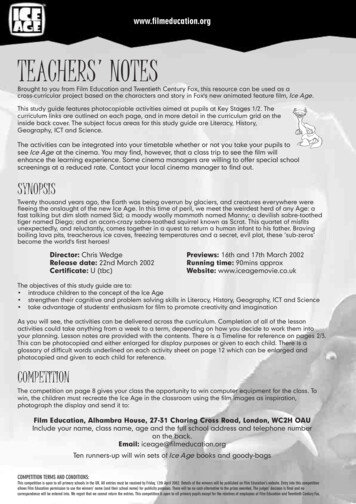
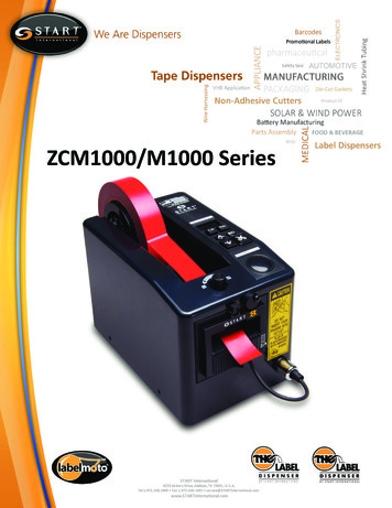
U300/UD300 Series Ice DispensersOrder parts onlinewww.follettice.comOperation, Service and Parts ManualService Number A23719 to B22204Single-sided dispensersModel U300Model U300BModel U300R400A/WModel U300BR400A/WModel U300R800A/WModel U300BR800A/WModel UD300R400A/WModel UD300R800A/WDual-sided dispensersModel UD300801 Church Lane Easton, PA 18040, USAToll free (800) 523-9361 (610) 252-7301Fax (610) 250-0696 www.follettice.com208782R03
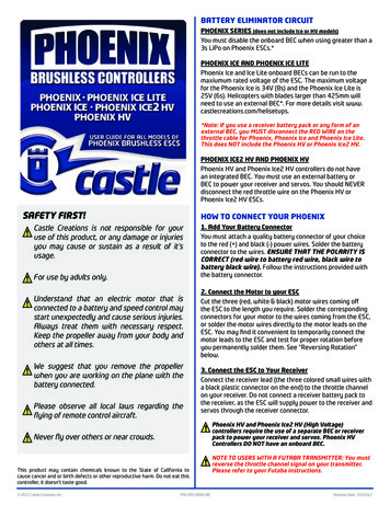
Welcome to FollettFollett ice dispensers enjoy a well-deserved reputation for excellent performance, long-term reliability andoutstanding after-the-sale support. To ensure that this dispenser delivers that same degree of service, we ask thatyou take a moment to review this manual before using the dispenser. Should you have any questions or requiretechnical help at any point, please call our technical service group at (800) 523-9361 or (610) 252-7301.Before you beginCheck your paperwork to determine which model you have. Following is an explanation of the different modelnumbers in the U300 series.U300BR400ACondenser type – A air-cooled, W water-cooledRemote icemaker(s) capacity and refrigerant – 400 400 lbs (181kg)/day, R404A800 800 lbs (363kg)/day, R404Aabsence of manual fill unitB integral beverage cooling. Absence of a B no integral beverage cooling.Approximate storage capacity in lbsConfiguration – U undercounter single-sided, UD undercounter dual-sided!Important cautions Storage area of dispenser contains mechanical, moving parts. Keep hands and arms clear of thisarea at all times. If access to this area is required, power to unit must be disconnected first. Follett manual load units accommodate most cube/cubelet ices up to 1" square and Follettcompressed nugget ice. Crushed, flake, bagged or congealed ice cannot be used. Use of these icescan jam dispenser and void warranty. Separate any “waffle-like” sections of cubes before adding todispenser. If you have questions concerning your ice type, call Follett’s customer service group at(800) 523-9361 or or ( 610) 252-7301. Follett recommends use of an activated carbon filter for units equipped with icemakers. Ice is slippery. Maintain counters and floors around dispenser in a clean and ice-free condition. Ice is food. Follow cleaning instructions to maintain cleanliness of delivered ice.2
Electrical Specifications – 115V, 60Hz, 1 phase!U300 series dispensers with remote icemaker(s) require separate circuit anddisconnect for each icemaker and dispenser.Single-sided modelsU300 – dispenser 6.0 ampsU300B – dispenser 7.0 ampsU300R400A/W – dispenser 6.0 amps, icemaker 11.0 ampsU300BR400A/W – dispenser 7.0 amps, icemaker 11.0 ampsU300R800A/W – dispenser 6.0 amps, icemakers 11.0 amps eachU300BR800A/W – dispenser 7.0 amps, icemakers 11.0 amps eachDual-sided modelsUD300 – dispenser 8.0 ampsUD300R400A/W – dispenser 8.0 amps, icemaker 11.0 ampsUD300R800A/W – dispenser 8.0 amps, icemakers 11.0 amps eachNote: Each icemaker and dispenser require separate circuit with electrical disconnect within10 feet (6m). Equipment ground required. Standard electrical – 115V, 60 Hz, 1 phase. Max. fusedispenser – 15 amps; each icemaker – 20 amps.!On all models with remote icemaker(s), black wire on icemaker control boardLINE VAC terminal must be moved to 24V terminal.Plumbing!Do not reduce size of drain lines or tie drains together.Dispenser – all models3/4" PVC slip fit bin drain1" PVC slip fit drain pan drain(s)1" PVC slip fit beverage bath drain (units with beverage cooling only)Note: Drains must be hard piped and insulated. Maintain 1/4" per foot (6mm per 304mm) min. slopeIcemaker – automatic load models only1/4" FPT water in1/2" MPT drain3/8" FPT condenser inlet (water-cooled condenser only)1/2" FPT condenser drain (water-cooled condenser only)Note: Water disconnect within 10 feet (3m) of icemaker(s) is required for automatic load units3
U300 series single-sided dispensersRequired clearances: 60" (1524mm) for installation 49" (1245mm) for auger removalFront viewDispenser onlywith no icemakerModel U300/U300B40.875"(1039mm)One icemaker –Models U300R5A/WU300BR5A/WEntranceTwo icemakers –beverageModels 642mm)54.875"(1394mm)12" p.drains6" min(153mm)Side view – ice dispense chuteIce waterbath(U300BR5A/W,U300BR10A/Wonly)32.375"22" (823mm)(559mm)Beveragelines enterthroughbottomJunctionboxesIcetransporttube entry8.5"(216mm)1"drains7"(178mm)3" (77mm)3/4"drain10"(254mm)9"2.5" 99mm)2"(51mm)
UD300 series dual-sided dispensersRequired clearances: 60" (1524mm) for installation 49" (1245mm) for auger removalFront view43.875"(1115mm)Dispenser only with noicemakerModel UD300ICE25.25"(642mm)Dispenser with one icemakerModels UD300R5A/WDispenser with two icemakersModels UD300R10A/W18.875" 12" min.(480mm)(305mm)17"(432mm)Beveragelines exitthroughbottom ofchaseDisp.drains54.875"(1394mm)12" min.(305mm)29.625"(753mm)Electricconn.6" min.(153mm)Side view opposite ice dispense chuteSide view - ice dispense chute32.375"(823mm)12.125"(308mm)beveragelines exitthroughbottom m)1"drains3/4"drain9"(229mm)8.5"(216mm)alt. icetransporttube 7mm)
To start up and operate dispenser1. Follow all cleaning and start-up instructions in U300 Installation Manual packed with dispenser beforeoperating dispenser.2. Turn power switches located under dispenser top to ON position.3. For manual load models, remove drain pan and fill storage area with compatible ice. (See caution on page 2of this manual concerning ices which may be used in this dispenser.)4. For automatic fill models, turn icemaker (bin signal) switch(es) located inside dispenser top to ON positionand begin to make ice.5. When dispenser has at least 6" (153mm) of ice in storage area, press lever or button to ensure that dispenseris operating properly.How dispenser worksFollett’s single-sided U300 series and dual-sided UD300 series ice dispensers are available in manual loadconfigurations (using ice from another source) or automatic load configurations (fed from one or two Follett 400 lb/day remote icemakers). An ice water bath beverage cooling system located directly behind valves is available forsingle-sided U300 series dispensers. Dual-sided units must use a separate mechanical cooling system to coolbeverage lines.In all models, ice is stored below counter in dispenser storage area. When dispense lever or button is pushed,dispense motor is activated. This causes wheel assembly in storage area to rotate counterclockwise, moving ice tovertical auger assembly. Vertical auger carries ice up to dispense chute where it drops by gravity into container.In automatic load models, ice is manufactured in either one or two Follett remote icemakers. These icemakersmay be located up to 20 ft (3m) away from dispenser. As water freezes to inside walls of icemaker evaporator, arotating stainless steel auger removes ice and carries it to top of evaporator assembly where it is compressed andextruded through an outlet port. The extruded ice is then pushed through tube to storage compartment ofdispenser. A bin thermostat shuts off icemaker when storage compartment is full.Periodic cleaning of dispenser!Do NOT run plastic parts (drain pan, dispense chute cover, dispense wheel) througha dishwasher.Solution A: Prepare cleaning solution (200 ppm available chlorine content) of Ecolab Mikro-chlor Cleaner orequal chlorinated detergent. Solution temperature must be at 75 – 125 F (23 – 52 C).Solution B: Prepare sanitizing solution (50 ppm available chlorine content) of Ecolab Mikro-chlor Cleaner orequal chlorinated detergent. Solution temperature must be at 75 – 125 F (23 – 52 C).Recommended daily cleaning of drain pan1. Remove all debris from drain pan.2. Pour 1 gallon (4L) hot water into drain pan to keep drain lines clear.Recommended weekly cleaning1. Remove drain pan(s) and grille(s) and wash with Solution A above. Rinse thoroughly.2. On units with beverage valves, remove nozzles and diffusers from valves, soak for at least 10 minutes incleaning Solution A, rinse, sanitize with Solution B and reinstall.3. Pour a solution of one cup (8 oz/237ml) household bleach mixed with one gallon (3.8L) hot water into drainpan(s) to help prevent algae growth in drain lines.Recommended quarterly cleaning (every 3 months)1.2.3.4.5.Empty all ice from dispenser.Remove dispenser top and turn bin signal switch(es) and dispenser power switch to OFF position.Remove dispenser drain pan(s) and grille(s).Remove thumbscrews from splash panel, lift up and out at bottom of panel and remove.Remove chute cover(s), dispense chute(s), auger tube and auger (see disassembly instructions).6
6. Remove yoke rods, drive shaft and dispense wheel (see disassembly instructions).7. Clean all components and bin storage area with Solution A, rinse thoroughly with clear water and sanitizewith Solution B. Caution: To avoid damage to switch, do not immerse chute cover in solution. Wipe onlywith cleaning cloth.8. On units with beverage valves, remove nozzles and diffusers from valves, soak for at least 10 minutes incleaning Solution A, rinse, sanitize with Solution B and reinstall.9. For models with integral ice water bath beverage cooling only:a. Lower Tygon drain tube found on drain connection side of waterbath into PVC waterbath drain and drainice water bath.b. Wash bath interior and components with Solution A, using a bottle brush to clean coils.c. Reposition Tygon waterbath drain line in UP position.d. Fill waterbath with Solution A and turn power back on.e. Allow pump to run for 2 minutes to clean pump and pump lines.f. Turn power OFF, drain bath and secure tube in UP position.Putting unit back in service after quarterly cleaning1. On units with integral beverage cooling, fill ice water bath manually with potable water. Add ice slowly enoughto avoid spillage over top of waterbath.2. Reassemble components.3. For manual load units, turn dispenser power switch to ON position and fill unit with approved ice (see cautionstatement page 2).4. For automatic load units, turn bin signal switch(es) and dispenser power switch to ON position and allowstorage area to fill.5. When dispenser has at least 6" (153mm) of ice in lower storage area, press dispense button or lever to testthat dispenser is functioning properly.Quarterly cleaning of icemaker system!Units with an icemaker require that icemaker be cleaned at least every three months ormore often if local water conditions dictate. Failure to clean icemaker system will resultin decreased performance and potential damage to icemaker. Refer to IcemakerOperation and Service Manual for instructions.Disassembly instructions for periodic cleaningDispense chute cover removal1.2.3.4.Remove dispenser top cover and turn three switches on electrical box OFF.Remove two Phillips head screws from top of black dispense chute cover.Pull chute cover forward and down to remove.On push-button actuated units, disconnect plug on harness.dispenser top cover(electrical box below)dispense chute cover(dispense mechanismbehind cover)splashpaneldispense tower(auger andauger tubeinside)drainpanFront view7
Gate assembly removal1. Remove black dispense chute cover.2. Remove thumbscrews on each side of focus chuteand remove.3. Remove quick release pins holding dispense gateassembly and chute.4. Lift gate up and over hinge tabs, then carefully pull andtilt to unhook from solenoid link.5. Pull ice chute toward you to unclip from dimples onchute mounting bracket.6. Pull ice chute and gate toward you and out throughpanel opening.Dispense chute assemblyquick release pinsgate assemblygate assemblyspringsAuger and auger tube removal1. Remove black dispense chute cover, focus chute,dispense chute and gate assembly.2. Remove drain pan.3. Remove thumbscrews from splash guard and remove.4. Remove thumbscrews from splash panel; lift and pullforward at base of panel and remove.5. Unplug auger motor at electrical box.6. Remove two 1/4-20 bolts holding auger motor toholddown bracket.7. Remove two thumbscrews from auger motor stabilizerbracket and aside.8. Lift auger motor off.9. Remove dispense chute mounting bracket assembly.10. Remove side panel of tower.11. Remove screw holding top auger tube ring to lower ring.12. Lift auger out of auger tube.13. Lift out auger tube, turning as needed to clear rivnutson side auger motor mounting bracket.ice chutemountingbracketice chuteU300 cutaway – front viewauger motorauger tubewheel motoraugertube ringaugerDispenser wheel removal1. Remove dispenser top and turn powerswitch OFF.2. Remove drain pan and ice bin accesscover below it.3. Remove splash guard and wheel motor access cover.4. Remove all ice from bin.5. Unplug wheel motor at electrical box and removeground wire.5. Remove wheel motor by pulling out two quickrelease pins.6. Lift drive shaft up through hole in countertop.7. Lift dispense wheel out through drain pan opening.fixed yokerods withbrackets (frontrod is lowest)8driveshaftFrontfixed rampedyoke rod withbracket (belowrotating drivebar)
Wiring diagramSingle-sided models with a service number of 5012607 or higher or any model withblue circuit boardJUNCTION BOXCONTROL BOARDPL9BLACKPOWERSWITCHPL13PUMP QC9GREENQC1WM QC10BLACKPL13GREENAM QC11PL9BLACKPL1BLACKPL1WMPL2BLACKPL2AMQC3L2AM . . . . . AUGER MOTORDISP . . . DISPENSEGND . . . . GROUNDIM . . . . . . ICE MAKERJB . . . . . .JUNCTION BOXPB . . . . . .PUSH BUTTONPL . . . . . .PLUGQC . . . . . QUICK CONNECTSOL . . . . SOLENOIDTRAN . . .TRANSFORMERT'STAT . .THERMOSTATWM . . . . .WHEEL UT POWERBLACKGREENGND L1JUNCTION BLUETemperature lightsREDSECONDARY (24V)TRANBLUEPL12PL12CONTROL BOARDBLUEQC21REDQC2224 VAC24 VACDRAIN WBLUEREDDISPENSEPL3SWITCH(PB OR LEVER)BLUEBATHSOLSOLPL6Low LED: Bath is atoptimal temperature forcold SOLHigh LED: Bathtemperature is aboveoptimal temperature. Thebath will fill with ice for 15seconds and will thenstop for 75 seconds. Iftemperature is still toohigh, cycle will repeat.PL4REDPL4DRAIN PANSWITCHTRANBEVERAGE L10BLUEPL14BIN SIGNALSWITCH IM#1YELLOWBLUEBLUEPL14PL7BLUETRANT'STAT1 2BLUEBIN SIGNALSWITCH IM#2PL8YELLOW24V JBBLUETRAN24V JBIM#1BINSIGNALIM#1BINSIGNAL9Temperature lightsprovide information onthe status of the icewaterbath. When lighted,the following LEDsindicate:BLUEPL7PL8REDREDQC22QC17Error and Low LEDs:After 15 minutes of fillcycling, bath is above40 F (4.4 C).Error (flashing) LED:Board not receivingsignal from sensor.
Wiring diagram – all dual-sided modelsGNDJUNCTION BOXJUNCTION BOXL1L2INPUT POWERPL13WHITEPL13BLK REDBLK BLKWHT WHT WHITEBLKBLKWMTBSAFETY SAFETYPL1PL1PL12PL12R1SWITCH SWITCH4 7#2#1(DP-NO) (DP-NO)PL13BLKPOWERSWITCHKBLKBLGREENBLKTBBLK .1(R)BLUE APL4R1REDTRANS.1(C)R1(B)PL4SODA VALVES – SIDE 1BLACKSAFETYQCV V V V V V V V V VPL10SWITCH #1RED(DP-NO)ACCESSORYPL1024V J.B.IM #1 YELBLUE 1BLUEBLUEREDREDYEL2BINBIN SIGNALSIGNALPL7PL7QCT-STATSWITCH IM#124V J.B.BLUEBLKQCKEYSWITCHBLUEBLUEYELLOWDISPENSESWITCH #2(PB OR B)REDPL6SODA VALVES – SIDE 2BLKQCBLUE ADISPENSESOLENOID LUETRANS.1(C)IM #2 BLUEREDBINPL8SIGNALBIN SIGNALPL8SWITCH IM#2TRANSFORMER NOID ITECRDISPENSESWITCH #1(PB OR LEVER)PL3WHTPL2PL2R2TRANSFORMER 1PRIAM BLUEQCBLACKSAFETYV V V V V V V V V VSWITCH #2(DP-NO)REDPL11ACCESSORY10TRANS.2(C)
Service and partsBefore calling for service1.2.3.4.Check that ice is in the dispenser and that congealed cubes are not causing a jam.Check that circuit breaker and switches are in ON position.Check that drain pan(s) are on securely. If ajar, neither dispenser nor valves will operate.Check that all drains are clear.For units equipped with Follett compressed nugget icemaker, see Icemaker Operation and Service Manual forservice and troubleshooting information.Dispenser troubleshooting guideSymptomIce does not dispense when switchis actuated. Auger motor does not run Wheel motor does not run Gate does not openIce does not dispense. Auger motor runs Wheel motor runs Gate does not openPossible cause1. Power switch faulty or in OFF position;loose connection.2. Faulty dispense switch.3. Faulty transformer/tripped breaker.4. Faulty fill board.5. Drain pan ajar.6. Faulty drain pan safety switch.1. Loose electrical connection.2. Linkage problem between solenoidand gate.3. Faulty solenoid.4. Faulty fill board.Solution1. Turn power switch to ON, checkconnections.2. Replace switch.3. Replace transformer/resetbreaker.4. Replace fill board.5. Check pan and reseat.6. Replace switch.1. Check connections.2. Check linkage.3. Replace solenoid.4. Replace fill board.Ice does not dispense. Auger motor does not run Wheel motor runs1. Loose electrical connection.2. Faulty auger motor.3. Faulty run capacitor.1. Check connections.2. Check auger motor.3. Check run capacitor.Ice does not dispense. Auger motor runs Wheel motor does not run1. Loose electrical connection.2. Faulty wheel motor.3. Faulty run capacitor.1. Check connections.2. Check wheel motor.3. Check capacitor.Warm drinks or soda foaming.1. No ice in storage bin.2. Water drained out of ice-waterbath.3. Faulty circulating pump.4. Faulty bath solenoid.5. Faulty thermistor.1. Fill storage area with ice orcheck icemaker operation. Pushreset on board.2. Check that ice-waterbath draintube is in fixed upright position.Push reset on board.3. Check pump. Push reset onboard.4. Replace bath solenoid. Push reseton board.5. Replace thermistor.If problem persists after following this basic troubleshooting guide, call Follett'stechnical service department at (800) 523-9361 or (610) 252-7301.11
SymptomBeverage valves not operating.Ice dispenses without actuation.No ice in dispenser.Possible causeSolution1. Faulty 24V transformer.2. Power switch faulty or in OFF position.3. Drain pan switch faulty or not depressed.4. Beverage key switch locking out access.1. Front ice gate stuck open.2. Faulty rear solenoid.3. Faulty pump/faulty bath temperaturesensor.4. Linkage pin dislodged or broken.5. Ice jam in rear chute.6. Misplaced bath sensor causing jam ofrear chute.7. Wire off rear solenoid causing ice todispense out front when filling bath,without actuation.1. Power switch in OFF position or faulty.2. Bin signal switches in OFF position orfaulty.3. Faulty bin thermostat.4. Faulty transformer.5. Icemaker related problem.6. Faulty or disconnected wiring.1. Check transformer & circuitbreaker.2. Check power switch.3. Check switch and placement ofdrain pan.4. Check valve lockout.1. Adjust gate (contact Follett)2. Replace solenoid.3. Replace pump or bath sensor.4. Check pin and reseat or replace ifbroken.5. Clear ice jam from chute.6. Remount bath sensor in properlocation.7. Reconnect wire.1. Check switch and replace ifnecessary.2. Check switch and replace ifnecessary.3. Replace bin thermostat.4. Replace transformer.5. Refer to icemaker Operation andService Manual for diagnosing.6. Check for power and bin signal onicemaker pc board.Disassembly instructions for service requirements only –NOT required for any cleaning procedure.Ice water bath pump motor removalPlan view ice water bath1. Disconnect electrical wires to pump.2. Remove two screws anchoring pump motor bracketto water bath.3. Loosen hose clamp on 1" (26mm) Tygon hose at pumpand pull hose free of pump motor.4. Slide motor and bracket toward center of dispenserand lift to remove.12drainhosebath sensorpump
Parts312394ICE11ICE5117610Single-side dispenser117610Dual-side dispenser1978Reference #12345Not shown67Not shown89Not shown1011Not shownNot shownNot shownNot shownNot shownNot shownNot shownNot shownNot shownNot shownNot shownNot shownPlan viewDescriptionLid, with graphics, single-sidedLid, with graphics, dual-sidedGraphics, “Follett”Access panel, tower, single-sidedAccess panel, tower, dual-sidedCover, ice opening (below drain pan)Drain pan assembly and grilleDrain pan, plasticSwitch, drain pan safetyGrille, drain panChute cover, dispense, push-button with switchChute cover, dispense, leverSplash guardThumbscrew, 10/32-1/2, splash guardSwitch, dispense, PBSwitch, dispense lever (includes boot and spacer)Boot, dispense switch button, leverAccess cover, wheel motor (behind splash guard)SkidCarton and fillersLip kit (plastic strip bordering ice bin opening and adhesive)Insulation, transport tube (sold by the foot)Tube, ice transport, 10 ftTube, ice transport, 20 ftPlug 2 lead, malePlug 2 lead, female13Part 3502334
14238415Top viewlower ringTop viewauger tube seal16reinforcingtab9565121061113714Reference #12Not shownNot shownNot shown3456789Not shownNot shownNot shown10111213Not shownNot shownNot shownNot shown1415Not shownNot shown16Front viewauger tubecountertopsectionDescriptionMotor, auger (includes capacitor), 100 RPM**Note: If your machine serial number precedes C69443, then youBracket, auger motor hold-downBracket, auger motor stabilizer, single-sided modelsBracket, auger motor stabilizer, dual-sided modelsSeal, shaft, auger motorAugerAuger tube (includes insulation)Insulation, auger tubeRing, auger tube, upperRing, auger tube, lowerMotor, wheel, Brother (includes capacitor)Bracket, wheel motorCapacitor, wheel motor, BrotherGasket, wheel motor bracketPin, quick release, wheel motor (2 required)Drive shaft assembly, for Brother motorAgitator rods, fixed, front and backWheel, dispenseBearing plate, bottom augerBearing, bottom, augerAgitator rod, rampedBracket, fixed agitator (3 used per unit)Thumbscrew, 10/32 x 3/4, fixed agitator bracket (2 required)Tee, drainThermostat box (includes 500514)ThermostatRetainer, ice hose (includes 2 thumbscrews)Bracket, ice hose and wheel motor14Part 211500514501764502050
1U300 dispense assemblyside viewU300 dispense assemblytop view2313746Reference #12345Not shown67Not shownNot shown4DescriptionGate, dispenseLinkage pin, gate/solenoidPin, quick release, 3" (77mm), gate and leverChute, iceSolenoidBoot, solenoidDispense mechanism assemblySpring, dispense mechanism (1 per side)Chute, focusLever, dispense5Part 01954501953546321Reference #123456Not shownNot shownNot shownNot shownNot shownDescriptionManifold, carbonated water (bev. cooled units)Syrup coilWaterbath ice guide assemblyBath sensorBracket, bath sensorPump, waterbathManifold, carbonated water (single-side, non-beverage cooled units)Tubing, vinyl, 1/2" (13mm) ID x 5/8" (17mm) OD (order by thefoot – 5 feet required for bath, 2 feet required for overflow)Tubing, vinyl, pump (order by the foot – 3 feet required)Syrup tube, insulated, non-bev. cooled units)Cap, carbonated water manifold valve fitting15Part 01966501967502062
Electrical boxSingle-sided models with Blue circuit board321POWERRESET54Reference #12345Not shownNot shownNot shownNot shownDescriptionControl board (blue)Stand-offTransformer, 65VASwitch, rockerControl box (includes all components)Keylock switch with leadsBracket, electric box supportThermostat (located behind splash panel in thermostat box)Key, beverage, lock switchPart 01286Electrical boxAll UD300 dual-sided models123Reference #12345Not shownNot shownNot shown45DescriptionRelay, 24VTransformer, 65VAControl box, dual-side modelsThermostatSwitch, rockerBracket, electric box supportKeylock switch with leadsKey, beverage, lock switch801 Church Lane Easton, PA 18040, USAToll free (800) 523-9361 (610) 252-7301Fax (610) 250-0696 www.follettice.comPart 08782R0303/10
U300/UD300 Series Ice Dispensers 208782R03 Model UD300 Model U300 Model U300B Model U300R400A/W Model U300BR400A/W Model U300R800A/W Model U300BR800A/W Model UD300R400A/W Model UD300R800A/W Order parts online www.follettice.com Single-sided dispensers Dual-sided dispensers 801 Church Lane Easton, PA 18040, USA Toll free (800) 523-9361 .