Transcription
CONTROLS AND DATA ACQUISITION ON ATLASD. W. Scudder, K. W. Hosack, W. M. Parsons, W. A. Reass, M. C. Thompson, F. J.Wysocki,Los Alamos National Laboratory1, Los Alamos, New Mexico 87545J. CreagerAllied Signal Federal Manufacturing and Technologies 2, Albuquerque, NMAbstractThe control and data acquisition systems for Atlas will use a large degreeof decentralization. By distributing control points close to the systemsbeing controlled we expect to simplify the task of isolating electonicsystems from the large expected EMI pulses, allow connection of thevarious parts ofthe system by high-level fiber-optic networks, allow asimple configuration of the control and data acquisition screen rooms, andsimplify the software efforts through the resulting modularization. TheAtlas control system must control capacitor charging, machine anddiagnostic timing and triggering, marx module diagnostics, vacuumsystems, gas handling for railgaps, safety interlocks, and oil handling.Many of these tasks will be performed by industrial-style programmablelogic controllers (PLCs). Each of 38 Marx bank maintenance units willhave a control and diagnostic package which will monitor both chargingand discharging current and railgap trigger timing. An unusual feature ofthese marx monitoring stations will be the inclusion of high speeddigitizers to record each marx module's output waveform, plusnanosecondresolution time interval meters to record the firing time of eachrailgap. The machine data acquisition system for Atlas will be builtaround an SQL database, use National Instruments LabVIEW software tocontrol data acquisition instruments and provide links for a variety ofexperimentalists' data analysis packages. World Wide Web access willprovide an interface through which users can monitor experimental dataand machine status.12Operated by the University of California for USDOEOperated for USDOE under contract DE-AC04-76-DP006150-7803-421 197/ 1 0.00 @1997 IEEE1285
Form ApprovedOMB No. 0704-0188Report Documentation PagePublic reporting burden for the collection of information is estimated to average 1 hour per response, including the time for reviewing instructions, searching existing data sources, gathering andmaintaining the data needed, and completing and reviewing the collection of information. Send comments regarding this burden estimate or any other aspect of this collection of information,including suggestions for reducing this burden, to Washington Headquarters Services, Directorate for Information Operations and Reports, 1215 Jefferson Davis Highway, Suite 1204, ArlingtonVA 22202-4302. Respondents should be aware that notwithstanding any other provision of law, no person shall be subject to a penalty for failing to comply with a collection of information if itdoes not display a currently valid OMB control number.1. REPORT DATE2. REPORT TYPEJUN 1997N/A3. DATES COVERED-4. TITLE AND SUBTITLE5a. CONTRACT NUMBERControls And Data Acquisition On Atlas5b. GRANT NUMBER5c. PROGRAM ELEMENT NUMBER6. AUTHOR(S)5d. PROJECT NUMBER5e. TASK NUMBER5f. WORK UNIT NUMBER7. PERFORMING ORGANIZATION NAME(S) AND ADDRESS(ES)Los Alamos National Labratory P.O. Box 1663 Los Alamos, NM 875759. SPONSORING/MONITORING AGENCY NAME(S) AND ADDRESS(ES)8. PERFORMING ORGANIZATIONREPORT NUMBER10. SPONSOR/MONITOR’S ACRONYM(S)11. SPONSOR/MONITOR’S REPORTNUMBER(S)12. DISTRIBUTION/AVAILABILITY STATEMENTApproved for public release, distribution unlimited13. SUPPLEMENTARY NOTESSee also ADM002371. 2013 IEEE Pulsed Power Conference, Digest of Technical Papers 1976-2013, andAbstracts of the 2013 IEEE International Conference on Plasma Science. Held in San Francisco, CA on16-21 June 2013. U.S. Government or Federal Purpose Rights License.14. ABSTRACTThe control and data acquisition systems for Atlas will use a large degree of decentralization. Bydistributing control points close to the systems being controlled we expect to simplify the task of isolatingelectonic systems from the large expected EMI pulses, allow connection of the various parts of the systemby high-level fiber-optic networks, allow a simple configuration of the control and data acquisition screenrooms, and simplifi the software efforts through the resulting modularization. The Atlas control systemmust control capacitor charging, machine and diagnostic timing and triggering, marx module diagnostics,vacuum systems, gas handling for railgaps, safety interlocks, and oil handling. Many of these tasks will beperformed by industrial-style programmable logic controllers (PLCS). Each of 38 Marx bank maintenanceunits will have a control and diagnostic package which will monitor both charging and discharging currentand railgap trigger timing. An unusual feature of these marx monitoring stations will be the inclusion ofhigh speed digitizers to record each marx modules output waveform, plus nanosecondresolution timeinterval meters to record the firing time of each railgap. The machine data acquisition system for Atlas willbe built around an SQL database, use National Instruments LabVIEW software to control data acquisitioninstruments and provide links for a variety of experimentalists data analysis packages. World Wide Webaccess will provide an interface through which users can monitor experimental data and machine status.15. SUBJECT TERMS16. SECURITY CLASSIFICATION OF:a. REPORTb. ABSTRACTc. THIS PAGEunclassifiedunclassifiedunclassified17. LIMITATION OFABSTRACT18. NUMBEROF PAGESSAR619a. NAME OFRESPONSIBLE PERSON
Standard Form 298 (Rev. 8-98)Prescribed by ANSI Std Z39-18
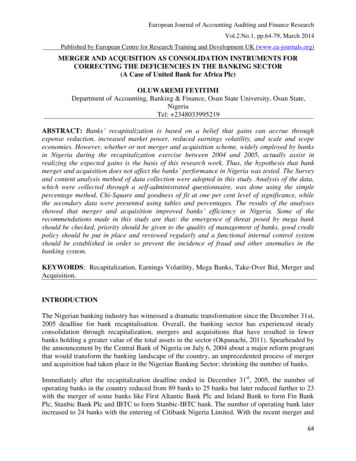
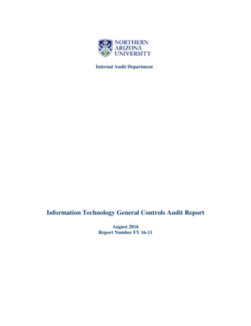
System overviewThe Atlas machine at Los Alamos National Laboratory is a large, 36 MJ, capacitor bankbeing built to carry out hydrodynamic experiments as part of the Department of Energy'sScience-Based Stockpile Stewardship program. The pulsed power systems andexperimental program are described in other papers at this conference. This paper willdescribe the control and data acquisition systems for Atlas.Several overal requirements have a significant impact on the control and data acquisitionsystem designs. The need to operate in an environment of large electromagnetic pulsesdrives us to use fiber optics wherever possible for transimission of signals. This plus thedesire to build a modular system drive us to locate control intelligence near to theequipment being controlled. Cost and the maturity of the controls market lead us to use- f - -- \*' ks--SWeeps--------!VacuumSfL ---- cCJu-il\lnterlockDoors ) loopScrambuttonsI' --I--- 1(:,-r)\\ [ ]-- ' FiberopticcontrolnetworkInternet-- ---(---,)GPIB': delay generators/trigger generatorsTiming&triggeringMaster controlstationI)-- \Fiberoptictr1gger1IIIsignalI;GascontrolsJ Fiber/opticGPIBGPIBto, fiber' \. . lllllil,)\-i:;ccc,' ; - -· - - IGIlliMIIi:dl----\\Master Data Acquisition \)-------Marxmonitoring"'\- ---- J--- (Il,c:· ;;#?m'!---c ---t----- . -- ClControl Room\1E rnetDataacquisitionworkstationsltd-!' \IFJ ) IJ )Figure 1. Control and data acquisition networks.commercial hardware and software wherever possible.Figurel provides a schematic overview ofthe system showing the several networkswhich will connect the various subsystems. These include networks to communicate with1286
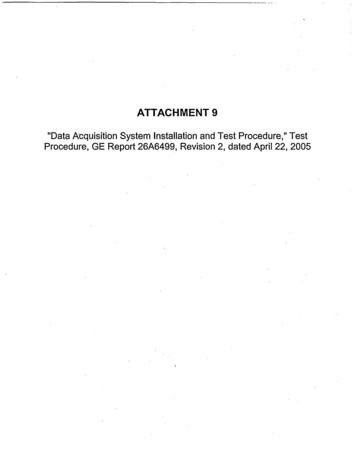
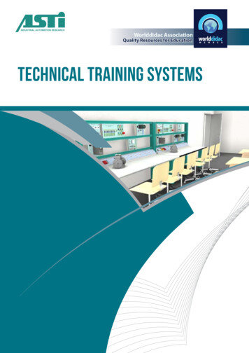
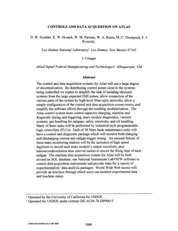
distributed programmable logic controllers (PLCs) (whose networks may be proprietaryto the PLC vendor or may use ethemet), fiber-optic GPIB to talk to distributed datarecording instruments, and ethemet connecting the control and data acquisition computersto the Los Alamos network and the Internet. Dedicated fiber links will carry time-criticalsignals such as marx bank triggering.This figure also illustrates that the Atlas control system will consist of a number ofsubsystems. These include: Master controlMarx module charging, diagnostics, safing and local gas controlInterlocksTiming and triggeringVacuum system controlOil transfer and filtering controlGas reclaimer and distribution control Master diagnosticsMaster controlThe master control system will communicate with the various subsystems, coordinatetheir operations, provide the operator interface (the vacuum system will also have a localconsole for operator instructions) and archive operation data with the database sharedwith the data acquisition system. This system will consist of several workstations,probably running the Windows NT operating system. The operator interface will usecommercial human-machine interface software.Marx bank control systemMost of the control operations on Atlas will involve local control boxes located as part ofeach of the Marx maintenance modules. A maintenance module consists of four Marxbanks, with 38 maintenance modules making up the whole system (for a total of 152Marx banks). The Marx control boxes will be called upon to carry out a wide variety offunctions.Figure 2 illustrates many of these functions. The power supplies to charge the Marxbanks are expected to be distributed near the Marx modules, so the Marx control boxeswill control the charging while monitoring for faults in the charge system. In addition,the control boxes will operate fast and slow dump switches, power supply disconnectswitches, monitor bank voltage and charge current, control power and gas to triggergenerators and control fill and flush valves on the railgaps (the main discharge switchesfor the Marxes).1287
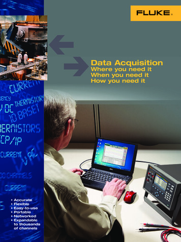
to-Trigger gap 0soft dumpHard dumpsD,n(.) 0E[2Figure 2. Marx module control box functions.A pair of fast diagnostics will be fielded in the Marx control boxes to monitor thedischarge cycle of the Marxes. Analog-to-digital converters at 40 Msamples/sec willrecord the discharge waveform of each Marx bank during each shot from Rogowski coilson their outputs. In addition, time interval meters with sub-nanosecond resolutionlooking at the signals from V -dot probes will measure the firing time of each rail gap. Inthe case of rail gap prefires, the V-dot signals will be available to initiate firing part or allof the rest of the rail gaps, as is judged appropriate. These fast diagnostics will share thefiber-optic communication channel used by the PLC in the control box.Each control box will provide a watchdog output to the interlock system, which will forcea machine shutdown if the control box logic fails to update the watchdog.Interlock systemPersonnel safety from high voltage and various other hazards will be provided by accesscontrol coordinated by the interlock system. Door and panel sensors will detect anyattempt to access areas containing hazards, and the interlock system will control means ofdisabling the hazards in those areas. In addtion to these sensors there will be scram1288
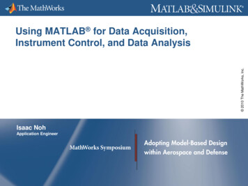
switches distributed liberally throughout areas containing hazards. A sweep system willconsist of switches distributed within exclusion areas and logic forcing an operator towalk through exclusion areas toggling the switches to assure that the areas are vacantDiagnostichazard enableswatchdogoutputsHoffman box. ell- ---111 JScrambuttons,---U-ni-nte ru p tibleljJpower supplyA.,."" -v ,;;;;:;:;;;;;:.,. -Figure 3. Interlock system showing redundant sensors and PLCs.before allowing hazardous systems to be enabled. Finally, watchdog signals from criticalPLCs will force sating in the event of a control failure.This system will consist of completely redundant PLCs, sensors and outputs, so that asingle point failure in the system cannot lead to a hazardous situation. All the locationsmonitored by the interlock system will be identifiable from either of the redundantsystems, so that any disagreement between the systems will identify and localize a systemfault, i.e. the complete system will be self-diagnosing.At least five different exclusion areas will be established for hazardous operations indifferent areas and under different machine operation modes. Since these will be definedin software, these areas can all be controlled by one (redundant) interlock system andreconfiguration will not require hardware changes.1289
Triggering and timingUnlike the other control subsystems, the triggering and timing system will not use a PLC.Programmable delay generators will be controlled by the master control system, and therest of the system will be hardwired. Signals leaving the screen room to fire the Marxbank triggering system and to trigger remote data acquisition systems will use high-speedanalog fiber-optic links.Other subsystemsThe remaining control subsystems, vacuum, oil and gas, will use PLCs in conventionalindustrial control configurations.Master data acquisition systemThe master data acquisition system will acquire data from machine performancediagnostics, provide scalable support to users' diagnostics, and coordinate access to allthe Atlas diagnostic data (user diagnostics and machine diagnostics).Atlas machine diagnostics will consist of a number of current probes located near thecenter of the machine, including B-dot pickups, Rogowski loops, fiber-optic-basedFaraday rotation diagnostics, and possibly voltage probes. The master data acquisitionsystem will provide signal handling and recording channels for these diagnostics.Recorders are expected to be housed in small, roll-around, screened enclosures locatednear the signal sources and communicating to the main data acquisition screen room over,for instance, fiber-optic GPIB or ethemet. Individual Marx bank current histories will becollected by the control system and trasferred to this system after each shot.The master data acquisition system should also provide recording channels to userdiagnostics, if needed, and the ability to interface to a user's standalone data recordingsystem if the user provides one. Users with standalone data acquisition will be requiredto make diagnostic data available to the master data acquisition system in a consistentform to be stored on the Atlas database server in a timely manner after a shot.The Atlas database server will be a high-end database engine and will server as arepository for all Atlas unclassified experimental results, configuration data and machineoperation parameter storage. The master control system will utilize the database to storeits configuration and operation logs.By storing all of the Atlas data in a single location, access to the data will be possibleover a world-wide web server. The server will make diagnostic data available forgraphing to a web browser and for download in any of a variety of common formats.1290
D. W. Scudder, K. W. Hosack, M. Parsons, A. Reass, C. Thompson, F. J. Wysocki, Los Alamos National Laboratory 1, Los Alamos, New Mexico 87545 J. Creager Allied Signal Federal Manufacturing and Technologies 2, Albuquerque, NM Abstract The control and data acquisition systems for Atlas will use a large degree of decentralization.