Transcription
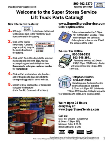
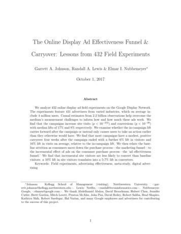
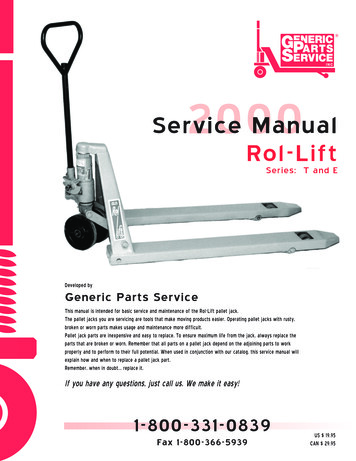
R2000Service ManualRol-LiftSeries: T and EDeveloped byGeneric Parts ServiceThis manual is intended for basic service and maintenance of the Rol-Lift pallet jack.The pallet jacks you are servicing are tools that make moving products easier. Operating pallet jacks with rusty,broken or worn parts makes usage and maintenance more difficult.Pallet jack parts are inexpensive and easy to replace. To ensure maximum life from the jack, always replace theparts that are broken or worn. Remember that all parts on a pallet jack depend on the adjoining parts to workproperly and to perform to their full potential. When used in conjunction with our catalog, this service manual willexplain how and when to replace a pallet jack part.Remember, when in doubt. replace it.If you have any questions, just call us. We make it easy!1-800-331-0839Fax 1-800-366-5939US 19.95CAN 29.95
CALL: 1-800-331-08392GENERIC PARTS SERVICE GPS, Inc.
Contents222334678101213141515Suggested AssembliesCommonly Used ToolsHelpful RemindersAxlesBushingsLoad Rollers and Load Roller BracketsSteer Wheels and AxleTraversePush RodsLifting LinkHandle Removal and InstallationHydraulic UnitInspectionService HintsRemovalInstallationCopyright 1999 by GPS, Inc. All rights reserved.Rol-Lift pallet jacks (all models) are products of L & L Fabrications.GENERIC PARTS SERVICE GPS,Inc.1CALL: 1-800-331-0839
Suggested Assembliesto Save Repair Time RL T5BOK-F-SuperSuper Seal Kit for Foot Control RL T5BOK-H-SuperSuper Seal Kit for Hand Control RL-32Ultra-Poly Steer Wheel Assembly RL-31-A-D-SuperSuper Ultra-Poly Load Roller Kit RL-31-DUltra-Poly Load Roller RL -31-3-SuperSuper Poly Load Roller KitCommonly Used Tools HammerJack Stand45 Snap ring pliers (large and small)PIN3/4” Wrench9/16” Wrench1/4” Allen wrench1/4” Pin punch3/16” Pin punchSoft hammer (nylon mallet)Anti-seize compoundLubricant (i.e. WD40 may be necessary to remove rusted parts)PUNCHSNAP RING PLIERSHelpful Reminders Never hammer directly on an axle; always use a pin punch. Always replace old roll pins and snap rings. Replace accessible bushings whenever the jack is torn down.CALL: 1-800-331-08392GENERIC PARTS SERVICE GPS, Inc.
AxlesInspectionIf the axle is bent, out-of-round or shows signs of wear, replace it. Check for worn snap ring grooves and roll pin holes.If these are damaged or worn, replace the axle. The standard height jacks have a knurl on one end of the axle toprevent it from spinning. Insert the end of the axle without the knurl first for easier installation.BushingsBushings are designed to wear out sooner than the mating parts. They are made of softer material and are expendable.It is recommended that anytime the jack is torn down to a point where the bushings are accessible, they be replaced.This will ensure longer life of the jack and will reduce the amount downtime. Bushings are very inexpensive and it iscost-effective to change them regularly.InspectionIf the bushings are cracked, broken, egg-shaped or worn more than 1/16" from the original size, replace them.Remember: If the jack is already disassembled, replace all accessible bushings.Tip: Coating axles and bushings with anti-seize compound before installation makes future maintenance easier.GENERIC PARTS SERVICE GPS,Inc.3CALL: 1-800-331-0839
Load Rollers andLoad Roller BracketsInspectionLoad rollers - Load rollers should not have flat spots or large pieces of metal imbedded in them (i.e. tacks, nails ormetal shavings). Any chips in the wheel that keep it from rolling smoothly indicate the need for replacement. If the wheelhas cracks, loose tread or does not turn freely, replace both wheels. Always change the wheels in pairs to reduce unevenwear. New load rollers have an outside diameter of 3" or 3 1/4". If the diameter is worn more than 1/4" from normal size,replacement is necessary.Load roller brackets - Inspect the bracket for cracks or broken welds. Ensure the axle holes are not out of round.Replace the bracket if it has worn thin due to prolonged rubbing on the floor. Also check the bushings closely (see BushingInspection).Snap RingLoad RollerLoad Roller BracketBearingLoad Roller AxlePush Rod AxleBushingPivot AxleRoll PinPush RodCALL: 1-800-331-08394GENERIC PARTS SERVICE GPS, Inc.
Load Rollers andLoad Roller BracketsRemovalTip: We recommend servicing one load roller assembly at a time, using the other assembly as a reference.Load rollersStandard height - Turn the jack over onto its side. Remove one of the snap rings and punch the axle out of the wheeland bracket. (10 minutes)Lowered height - Turn the jack over onto its side. Remove the roll pin and punch the axle out of the wheel and bracket.(10 minutes)Load roller bracketsStandard height - Turn the jack over onto its side and remove the load roller. Remove the snap ring on the pivot axleand punch it out of the frame and bracket. Remove the snap ring and drive the push rod axle out of the bracket.(15 minutes)Lowered height - Turn the jack over onto its side and remove the load roller. Remove the roll pin securing the pivotaxle in place and punch the axle out. Remove the roll pin fastening the push rod axle to the bracket and drive the axle out.(15 minutes)InstallationLoad roller bracketsStandard height - With the jack on its side, insert the axle through the bracket and the push rod. Secure it in placewith the snap rings. Attach the bracket to the frame by inserting the pivot axle through the frame and bracket. Secure inplace with the snap rings. Install the load roller. Insert the end of the axle without the knurl first for easier installation.(15 minutes)Lowered height - With the jack on its side, insert the push rod axle into the bracket and push rod. Secure it in placewith the roll pin. Fasten the bracket to the frame by inserting the pivot axle through the frame and bracket and securingthe axle in place with the roll pin. Install the load roller. (15 minutes)Load rollersStandard height - With the jack on its side, insert the axle through the bracket and wheel. Secure it in place with thesnap ring. Insert the end of the axle without the knurl first for easier installation. (10 minutes)Lowered height - With the jack on its side, insert the axle through the bracket and wheel. Secure the axle in place byreplacing the roll pin. (10 minutes)GENERIC PARTS SERVICE GPS,Inc.5CALL: 1-800-331-0839
Steer Wheels and AxleInspectionSteer wheels should not have flat spots or large pieces of metal imbedded in them (i.e. tacks, nails or metal shavings). Chips in the wheel,which keep it from rolling smoothly, indicate the need for replacement. Steer wheels should turn freely. They should not rub the bottom ofthe traverse. If they do, check for the correct installation of the snap ring under the traverse. Rol-Lifts older style steer wheel has an 8"diameter and their newer style has a 7 1/2" diameter. If the wheel is worn more than 1/4" from the normal diameter, replacement isnecessary.RemovalSteer wheelsStandard height - With the jack on its side, remove the roll pin and the wheelwill be free to slide off. (10 minutes)Lowered height - Turn the jack onto its side, remove the snap ring and thewheel will be free to slide off. (10 minutes)Hydraulic UnitSteer wheel axleStandard height - Turn the jack onto its side and remove the steer wheels.Remove the snap ring on the pin that fastens the axle to the stem of the hydraulicunit. Punch the pin out of the stem and the steer wheel axle will be free toremove. (15 minutes)Lowered height - Turn the jack onto its side and remove the steer wheels.Remove the snap ring on the pin that fastens the axle to the stem of the hydraulicunit. Punch the pin out of the stem and the steer wheel axle will be free toremove. (15 minutes)TraverseSnap RingSteer Wheel AxlePinSnapRingRoll PinInstallationSteer WheelSteer wheel axleStandard height - With the jack on its side, line up the pivot hole on the steer wheel axle with the hole in the stem of the hydraulic unitand insert the pin that attaches the axle to the hydraulic unit. Secure the pin in place with its snap rings. Slide the steer wheels onto the axleand secure them in place with the roll pins. (15 minutes)Lowered height - With the jack on its side, line up the pivot hole on the steer wheel axle with the hole in the stem of the hydraulic unitand insert the pin that attaches the axle to the hydraulic unit. Secure the pin in place with its snap rings. Slide the steer wheels onto the axleand secure them in place with the snap rings. (15 minutes)Steer wheelsStandard height - Slide the steer wheels onto the axle and secure them in place with the roll pins.(10 minutes)Lowered height - Slide the steer wheels onto the axle and secure them in place with the snap rings.(10 minutes)CALL: 1-800-331-08396GENERIC PARTS SERVICE GPS, Inc.
TraverseInspectionThere are few things that can be wrong with the traverse. Wear can occur on the bearing shoulder or where the shoulder pinsattach to the lifting link. If these areas are egg-shaped or out-of-round, replace the traverse.RemovalPump up the jack to gain access to the snap ring that secures the thrust bearing assembly, on top of the ram, to the A-Frame.Turn the jack onto its side and remove the steer wheels, steer wheel axle (see Steer Wheels and Axle) and the snap ring thatholds the traverse in place on the stem of the hydraulic unit. Turn the jack back over and carefully lower the stem of thehydraulic unit onto the ground. Remove the snap ring securing the upper thrust bearing assembly in place, and lift the frame offof the ram. Pull the hydraulic unit out of the traverse with the traverse bearing. Punch out the roll pins that fasten the shoulderpins to the traverse. Remove the shoulder pins and the traverse. (25 minutes)InstallationPosition the traverse between the ears of the lifting link. Insert the shoulder bolts through the lifting link and into the traverse.Secure the shoulder pins with their roll pins. Position the traverse bearing onto the stem of the hydraulic unit and slide thehydraulic unit into the traverse. Raise the frame and insert the top of the ram, with the thrust bearing assembly still in place,into the top of the A-Frame. Pump the jack up to its maximum height and insert the snap ring that secures the thrust bearingassembly in place. Install the snap ring under the traverse onto the stem of the hydraulic unit. Assemble the steer wheel axleand the steer wheels (see Steer Wheels and Axle) to the hydraulic unit. (25 minutes)RamLifting LinkLower Thrust BearingRoll PinTraverseBushingWasherGrease ZerkShoulder PinSnap RingGENERIC PARTS SERVICE GPS,Inc.7CALL: 1-800-331-0839
Push RodsInspectionWhen inspecting the push rods, look for broken or cracked welds, bends, missing roll pins and worn bushings. It is best to mark the position of theeyebolt and nut in relation to the push rod to ensure proper adjustment during installation.Removal - T SeriesRemoval - E SeriesStandard height - Fully lower the jack and then turn the jack overso that the undercarriage is facing up. Remove one of the snap rings onthe pivot axle and drive the pivot axle out of the bracket and frame.Remove one of the snap rings on the push rod axle and drive the axleout of the bracket. Loosen the set screw holding the eccentric in theproper adjustment, remove the snap ring securing the eccentric to thelifting link and drive the eccentric out of the lifting link through theaccess hole in the frame. It is helpful to mark the adjustment of theeccentric for easier adjustment of the push rods during assembly.(25 minutes)Standard height - Fully lower the jack and then turn the jack overso that the undercarriage is facing up. Remove one of the snap rings onthe pivot axle and drive the pivot axle out of the bracket and frame.Remove one of the snap rings on the push rod axle and drive the axleout of the bracket. Loosen the nut and unscrew the push rod from theeye bolt. It is helpful to mark the adjustment of the eye bolt for properinstallation.(20 minutes)Lowered height - Fully lower the jack and then turn the jack overso that the undercarriage is facing up. Drive the roll pin fastening thepivot axle to the load roller bracket out and remove the pivot axle.Drive the roll pin that fastens the push rod axle to the load rollerbracket out and remove the axle. Unscrew the push rod from the eyebolt. It is helpful to mark the adjustment of the eye bolt for properinstallation. (20 minutes)Lowered height - Fully lower the jack and then turn the jack overso that the undercarriage is facing up. Drive out the roll pin fasteningthe pivot axle to the load roller bracket and remove the pivot axle.Drive the roll pin out that fastens the push rod axle to the load rollerbracket and remove the axle. Unscrew the push rod from the eye bolt.it is helpful to mark the adjustment of the eye bolt for properinstallation. (20 minutes)E Series - Standard HeightLoad RollerLifting Link ShaftBearingBracketPush RodAxleLoad RollerAxleBushingPush RodLifting LinkPivot AxleSnap RingSnap RingEyeboltCALL: 1-800-331-08398GENERIC PARTS SERVICE GPS, Inc.
Push RodsInstallation - T SeriesInstallation - E SeriesStandard height - Insert the eccentric through the lifting link andpush rod. Secure it with its snap ring. Insert the push rod axle throughthe bracket and push rod. Secure with its snap rings. Slide the pivot axlethrough the frame and bracket. Secure the axle in place with its snaprings.Turn the jack upright and fully lower it. Adjust the push rod by turningthe eccentric with a large screwdriver through the access hole on theside of the frame. By turning the eccentric you effectively lengthen orshorten the push rod.Test the adjustment by pumping the jack up and then lowering it. If theforks hit bottom at the same time, then it is adjusted correctly. If onefork hits bottom before the other, then further adjustment is necessary.Turn the eccentric about 1/8 to 1/4 of a turn and test the adjustmentagain. Once the push rods are adjusted correctly, turn the jack overonto its side and tighten the set screw down to keep the eccentric fromturning. (30 minutes)Standard height - Thread the push rod onto the eye bolt. Try tomatch the other side if it is still assembled. If it isn't, adjust the lengthafter you have assembled the load roller bracket onto the push rod.Insert the push rod axle through the bracket and push rod. Secure theaxle with the snap rings. Insert the pivot axle through the frame andbracket. Secure the axle in the frame with the snap rings.If you have not adjusted the push rod yet, place the lifting link in aposition that matches a fully lowered position. Spin the push rod andbracket one way or the other until the pivot axle hole on the bracketlines up with the frame. Then insert and secure the pivot axle.Test the adjustment by pumping the jack up and then lowering it. If theforks hit bottom at the same time, then it is adjusted correctly. Turn thejack over onto its side and tighten the nut on the eye bolt up to thepush rod to secure the adjustment during any other repairs. If one forkhits bottom before the other, then further adjustment is necessary. Youcan either shorten the push rod on the fork that hits first or lengthenthe push rod on the fork that hits second. Keep adjusting until bothforks hit bottom at the same time. (25 minutes)Lowered height - Thread the push rod onto the eye bolt and try tomatch the other side if it is still assembled. If it isn't, adjust the lengthafter you have assembled the load roller bracket onto the push rod.Insert the push rod axle through the bracket and push rod. Secure theaxle in the bracket with the roll pin. Insert the pivot axle through theframe and bracket. Secure the axle in the bracket with the roll pin.If you have not adjusted the push rod yet, place the lifting link in aposition that matches a fully lowered position. Spin the push rod andbracket one way or the other until the pivot axle hole on the bracketlines up with the frame. Then insert and secure the pivot axle.Test the adjustment by pumping the jack up and then lowering it. If theforks hit bottom at the same time, then it is adjusted correctly.If one fork hits bottom before the other, then further adjustment isnecessary. You can either shorten the push rod on the fork that hitsfirst or lengthen the push rod on the fork that hits second.It is easier if you do the adjustment on the eye bolt end once the loadwheel bracket is attached to the frame. Remove one of the snap ringson the pin that fastens the eye bolt to the lifting link, and punch the pinout. Pull the eye bolt away from the lifting link and turn it one way orthe other to adjust as needed. Assemble the eye bolt and the lifting linkwith the pin and its snap rings. Turn the jack over and test theadjustment. Keep adjusting until both forks hit bottom at the same time.(25 minutes)GENERIC PARTS SERVICE GPS,Inc.Lowered height - Thread the push rod onto the eye bolt. Try tomatch the other side if it is still assembled. If it isn't, adjust the lengthafter you have assembled the load roller bracket onto the push rod.Insert the push rod axle through the bracket and push rod. Secure theaxle in the bracket with the roll pin. Insert the pivot axle through theframe and bracket. Secure the axle in the bracket with the roll pin.If you have not adjusted the push rod yet, place the lifting link in aposition that matches a fully lowered position. Spin the push rod andbracket one way or the other until the pivot axle hole on the bracketlines up with the frame. Then insert and secure the pivot axle.Test the adjustment by pumping the jack up and then lowering it. If theforks hit bottom at the same time, then it is adjusted correctly. If onefork hits bottom before the other, then further adjustment is necessary.You can either shorten the push rod on the fork that hits first orlengthen the push rod on the fork that hits second. Keep adjusting untilboth forks hit bottom at the same time. (25 minutes)9CALL: 1-800-331-0839
Lifting LinkInspectionCheck lifting link for out-of-round holes, cracks in welds, or bent ears. If any of these conditions exist, replace the lifting link.We suggest that you work on one side of the jack at a time, so you can use the other side as a reference. The T Seriesstandard height uses an eccentric for adjustment and the lowered height uses an eye bolt for adjustment. Both standard andlowered height of the E Series uses an eye bolt, as well.Removal - T SeriesStandard height - Pump the jack up to its maximum height. Remove the snap ring under the A-Frame that secures theupper thrust bearing assembly on the ram to the jack. Lift the jack off of the ram and pivot the hydraulic unit away from theframe. Remove the shoulder bolts fastening the traverse to the lifting link, by driving out their roll pins. Remove the hydraulicunit and traverse assembly as one piece. Turn the jack over so that the undercarriage is facing up. Loosen the set screw thatholds the eccentric in adjustment. Remove the snap ring on the eccentric, and pull the eccentric out through the access holein the side of the frame. Remove the snap ring on the lifting link shaft. Use a hammer and punch to drive the shaft out farenough to grip it on the other side, and pull it out. (45 minutes)Lowered height - (see E Series Lifting Link Removal, below)Removal - E SeriesStandard and Lowered height - Pump the jack up to its maximum height. Remove the snap ring under theA-Frame that secures the upper thrust bearing assembly on the ram to the jack. Lift the jack off of the ram and pivot thehydraulic unit away from the frame. Remove the shoulder bolts, fastening the traverse to the lifting link, by driving out theirroll pins. Remove the hydraulic unit and traverse assembly as one piece. Turn the jack over so that the undercarriage isfacing up. Remove the pivot axle. Remove the snap ring on the axle for standard height jacks, or the roll pin on loweredheight jacks. Then remove the eye bolt (with the push rod still attached) by removing the snap ring that fastens it onto thelifting link. Remove the snap ring on the lifting link shaft. Use a hammer and punch to drive the shaft out far enough to gripit on the other side, and pull it out. (45 minutes)CALL: 1-800-331-083910GENERIC PARTS SERVICE GPS, Inc.
Lifting LinkInstallationTurn the jack over so that the undercarriage of the jack facing up, position the lifting link inthe frame. Insert the lifting link shaft and secure it with its snap ring. Attach the push rod(see Push Rods) and the load roller bracket (see Load Roller Brackets). Turn the jack uprightand install the traverse with the hydraulic unit and steer wheel assembly still attached (seeTraverse). Position the ram and upper thrust bearing assembly into the A-Frame. Secure itwith the snap ring. (45 minutes)Snap RingLoad RollerLifting LinkLifting LinkShaftBracketE SERIESBearingSnapRingTraversePush Rod AxleNutShoulder PinPivot AxleSnap RingPinEyeboltSteerWheel AxleBearingGENERIC PARTS SERVICEInc.Snap RingEccentric PinSteerWheel GPS,TSERIES11CALL: 1-800-331-0839
Handle Removal and InstallationInspectionInspect the handle for cracks and structural integrity. There shouldbe minimal side play in the handle socket. Check for worn bushings.If bushings are not replaced regularly, the handle socket holes canbecome worn. This may require complete handle socketreplacement to prevent unnecessary wear on mating parts. Also,inspect the pivot shaft and the piston pusher for wear. If any of theabove parts are worn more than 1/16", replace them.Handle SocketFoot Control RemovalRoll PinRemove the roll pin. Pull up on the handle while twisting from sideto side. (5 minutes)Foot Control InstallationPiston PusherInsert the handle into the handle socket so the hole on the handlealigns with the hole in the handle socket. Drive the roll pin in placeto secure the handle. (5 minutes)Newer StyleHand Control RemovalRemove the locking nut and the adjustment screw in the fulcrumbar. This will allow the glide pin and the ball to slide out of theway, and allow room for the actuator to come out of the handlepivot shaft. Remove the handle bolt and carefully pull up on thehandle to pull the actuator out of the handle pivot shaft. Do nottwist the handle until the actuator is out of the handle pivot shaft.(5 minutes)Hand Control InstallationInsert handle into handle socket so holes will align whencompletely inserted. While pushing the handle into the socket, theactuator must slide completely in the handle pivot shaft. Slide theball and then the glide pin into the pivot shaft. Replace handle bolt.Install the adjusting screw and locking nut back into the fulcrumbar. (10 minutes)ActuatorHandlePivotShaftBallHandle SocketFulcrum BarHandle BoltGlide PinAdjustment Screw Locking NutCALL: 1-800-331-083912GENERIC PARTS SERVICE GPS, Inc.
Hydraulic UnitInspectionInspect the outside of the pump for oil leaks. Test the unit, under a load, to determine if there is a problem. This can be done by lifting a heavypallet and letting it stand for 15-20 minutes. Below are symptoms and solutions to common hydraulic unit failures. If the following solutions fail tocorrect the problem, a complete rebuild of the malfunctioning unit may be necessary. Please refer to our catalog for information about ordering theappropriate seal kit or take advantage of our hydraulic unit exchange program.Jack fails to lift load Air Lock in Pump (Foot or Hand Control) - Place the control mechanism in the release position, then pump handle rapidly 10-15times. (5 minutes) Low Fluid Level (Foot or Hand Control) - With the jack in a lowered position, remove filler plug slowly to avoid rapiddepressurization. Using RL-HO oil, fill the reservoir until the oil is level with the fill plug hole. Replace filler plug, rotating no more than 360degrees. Place the control mechanism in the lift position and pump the jack up to its maximum height. Remove filler plug to allow air into thereservoir, then replace the filler plug, creating a snug fit. Do not overtighten. (10 minutes)NOTE: If lack of oil pressure is evident by short lifting strokes, repeat procedure. If failure is still evident, see Air Lock in Pump. Hand Control Out of Adjustment - Place hand control in neutral. Loosen the lock nut on the adjustment screw. Back the set screw out3-4 turns, being careful not to completely remove it. Pump the handle slowly to raise the jack, then turn the adjusting screw in until the jackstops raising. Now turn the adjusting screw an additional 1/4 of a turn and tighten the lock nut. Test the jack by placing the handle control inthe neutral position, then pump the handle. The jack should not raise. Place the handle control in the lower position and the jack should lower.(see Diagram on page 12) (10 minutes) Foot Control Malfunctioning - If the foot control shoulder bolt is bent, replace it. If the foot control pedal is worn to the point that it isnot properly engaging the actuator pin, replace the foot control pedal. If the foot control pedal appears to be properly engaging the actuatorpin, the problem is probably within the hydraulic unit.Jack fails to lower The foot control pedal shoulder bolt is loose or bent. Replace if necessary.The hand control may be out of adjustment (see Hand Control Out of Adjustment).Oil is too dense. Empty unit and refill with RL-HO oil.Look for any bent or damaged frame parts (lifting link, push rod, etc.). Bent or damaged frame parts should be replaced.Debris blocking an oil channel in the hydraulic unit. Contact us for our hydraulic core exchange program.Jack lifts in short increments Loss of oil pressure - see Low Fluid Level. Reservoir filler plug leaking - Replace the washer and restore air pressure (see Low Fluid Level).One fork lifts, the other does notCheck for damage in the following areas and their attached parts: Lifting link (lifting link pin and traverse shoulder pin) Pushrod Load roller bracket (pivot axle)GENERIC PARTS SERVICE GPS,Inc.13CALL: 1-800-331-0839
Hydraulic UnitService Hints Tampering and abuse are two of the most common problems. In most cases, minor repairs become major wheninexperienced people attempt to rebuild a hydraulic unit. If you come across a unit that looks like it has beentampered with or modified, inspect the unit carefully to be sure it can be rebuilt or call Generic Parts Service fortechnical assistance. The ram is chromed and the pump piston polished to a fine finish for maximum seal life and minimum oil leakage.If you see these surfaces nicked or pitted, this will cause the unit to fail in a short time. Replace any rusty ordamaged parts that will cause premature wear on their mating parts or the body of the hydraulic unit. The high pressure relief valve is pre-adjusted by the factory and usually needs no attention. Use RL-HO hydraulic oil. Rol-Lift jacks use oil which is less dense than most pallet jack hydraulic oil.Do not use automotive oil or hydraulic brake fluid.CALL: 1-800-331-083914GENERIC PARTS SERVICE GPS, Inc.
Hydraulic UnitRemovalPump the jack to its maximum height and turn the jack onto its side. Remove the steer wheels and axle (see SteerWheels and Axle Removal) and the snap ring under the traverse on the stem of the hydraulic unit. Turn the jack upright;be careful no to damage the stem of the hydraulic unit while lowering. Remove the snap ring securing the upper thrustbearing assembly on the ram to the A-Frame. Lift the frame off the ram, tip the handle and hydraulic unit away from theframe and rest both pieces on the ground. Pull the hydraulic unit out of the traverse and remove the handle if necessary(see Handle Removal). (45 minutes)InstallationSlide the stem of the hydraulic unit into the traverse with the lower thrust bearing already in place on the stem. Insertthe top of the ram and the upper thrust bearing assembly into the A-Frame and secure in place with the snap ring.Carefully turn the jack onto its side, keeping the hydraulic unit in the traverse and frame. Attach the snap ring to thestem of the hydraulic unit under the traverse. Install the steer wheel assembly (see Steer Wheel and Axle Installation)and the handle, if necessary (see Handle Installation). Bleed the hydraulic unit (see Air Lock and Pump). (45 minutes)Bearing CapHandleUpper Thrust BearingSnap RingThrust CollarSnap RingHydraulic UnitLower Thrust BearingTraverseSnap RingAxle PinSnap RingGENERIC PARTS SERVICE GPS,Inc.Steer Wheel Axle15CALL: 1-800-331-0839
This manual is intended for basic service and maintenance of the Rol-Lift pallet jack. The pallet jacks you are servicing are tools that make moving products easier. Operating pallet jacks with rusty, broken or worn parts makes usage and maintenance more difficult. Pallet jack parts are inexpensive and easy to replace. To ensure maximum life .