Transcription
MANUFACTUREDHOUSINGINSTALLATIONMANUAL
TABLE OF CONTENTSDescriptionPageABS Stabilizer PlateAnchors - AsphaltAnchors - Concrete “J”Anchors - Concrete SlabAnchors - Cross Drive RockAnchors - Deep SetAnchors - InstallationAnchors - StabilizersAnchors - X-Plate/StabilizerDrive Machine (EDM)Hardware Kits - Adjustable OutriggerHardware Kits - Perimeter Pier SupportHardware Kits - Propane Anchor KitsHardware Kits - Spring Hanger KitsPad Installation - ABSPier Installation - SteelQuik Set StabilizerRadco Listings - ABS & Steel PadsRadco Listings - AnchorsSoil Classification ChartsStabilizer Plate InstallationStrap - Angle FrameStrap - BuckleStrap - CertificationStrap - Crimping SealsStrap - Frame TieStrap - Gator Beam ClampStrap - InstallationStrap - ProtectorsStrap - Sidewall ConnectorStrap - Speed WrenchStrap - Strap TensioningStrap - Swivel ConnectorWind Zone 14-5101614111114161313151212153Manufactured Housing Products Division605 Stonehill Drive SW, Atlanta, Georgia 30336800-241-1806 404-344-0000 www.tiedown.comISO 9001:2015 CertificationIntellectual property of TIE DOWN Inc. 2018 TIE DOWN, Inc.Instruction #08235 (D12 Rev. 3/11/20)2605 Stonehill Drive SW Atlanta, Georgia 30336 404.344.0000 www.tiedown.com
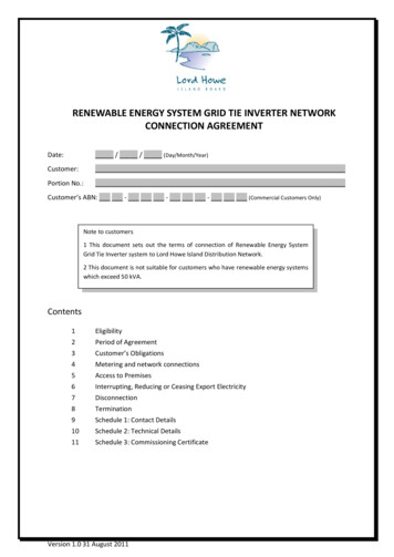
KNOW YOUR WIND ZONEUS WIND ZONE CHARTEach manufactured home must be designedaccording to the federal Manufactured HomeConstruction and Safety Standards at 24CFR 3280, commonly called the HUD Code.The HUD Code stipulates, at §3280.305(c)(1) and §3280.305(c)(2), that the home shallbe designed and constructed to conform toone of three wind load zones. The appropriate wind zone used in design is dependenton where the home will be initially installed.Zone IIZone IZoneHawaiiZone IIIIIAlaskaIIneZoHomes designed and constructed to ahigher Wind Zone can be installed in a lowerWind Zone (a Wind Zone III home can beinstalled in a Wind Zone I or II location).However, a Wind Zone I home cannot beinstalled in either a Wind Zone II or III area.Zone IZone IIIZone IIIZone IZone IIZone IIIZone IIIWIND ZONE IIIHawaiiAlaskaFloridaEntire StateCoastal regionsBroward, Charlotte, Collier, Dade, Franklin, Gulf, Hendry, Lee, Martin, Manatee, Monroe, Palm Beach,Pinellas, & SarasotaLouisianaParishes of Jefferson, La Fourche, Orleans, Plaquemines, St. Bernard, St Charles, St. Mary,& TerrebonneNorth Carolina Carteret, Dare, and HydeTerritoriesAmerica Samoa, Guam, Northern Mariana Islands, Puerto Rico, Trust Territory of the PacificIslands & The US Virgin IslandsWIND ZONE IIAlabamaFloridaGeorgiaLouisianaBaldwin & MobileAll counties except those listed below as within Wind Zone IIIBryan, Camden, Chatham, Glynn, Liberty & MacintoshParishes of Acadia, Ascension, Assumption, Calcasieu, Cameron, East Baton Rouge,East Feliciana, Evangeline, Iberville, Jefferson Davis, Lafayette, Livingston, Pointe Coupee,St. Helena, St. James, St. John the Baptist, St. Landry, St. Martin, St Tammany, Tangipahoa,Vermillion, Washington, West Baton Rouge & West FlelicianaMaineHancock & WashingtonMassachusetts Barnstable, Bristol, Dukes, Nantucket & PlymouthMississippiGeorge, Hancock, Harrison, Jaskson, Pearl River & StoneNorth Carolina Beaufort, Brunswick, Camden, Chowan, Columbus, Craven, Currituck, Jones, New Hanover, Onslow,Pamlico, Pasquotank, Pender, Perquimans, Tyrrell, & WashingtonSouth Carolina Beaufort, Berkeley, Charleston, Colleton, Dorcherster, Georgetown, Horry, Jasper, & WilliamsburgTexasAransas, Brazoria, Calhoun, Cameron, Chambers, Galveston, Jefferson, Kenedy,Kleberg, Matogorda, Nueces, Orange, Refugio, San Patricio & WillacyVirginaCities of Chesapeake, Norfolk, Portsmouth, Princess Anne & Virginia BeachWIND ZONE IAll States, Counties, Parishes or Cities not listed above.3
SOIL CLASSIFICATIONSOIL CLASSIFICATION CHARTSGround anchors are designed for different soil classifications: longer models for loose soils, shorter models for hardersoils. Prior to installing any ground anchor model, the soil must be tested (with a Soil Test Probe) in order to matchapproved ground anchor model with site soil class.WARNING: Before ground anchor installation, determine that the anchor locations around home will not be close toany underground electrical cables, water lines or sewer piping. Failure to determine the location of electrical cablesmay result in serious personal injury.Soil Test ProbeThe Soil Test Probe is used to determine the soil conditions below the surface near the anchor’s helix. Using the SoilTest Probe will ensure maximum anchor holding strength by indicating the proper anchor model for each soil condition.Using the chart provided, a probe reading can be converted to the recommended anchor for every soil condition.Instructions1. Place probe tip into ground where you intend to place the anchor. Using a 15/16” hex socket with a ratchet orbreaker bar, rotate the probe in a clockwise direction. (An electric drive machine with an adapter head mayalso be used)2. Drive (rotate) the torque probe into the soil until reaching a depth equal to the length of the anchor being installed.3. To determine the soil classification: Place wrench adapter onto torque wrench. Insert hex portion of wrench adapter onto the earth probe. Support probe shaft with one hand, while rotating probe steadily with the wrench. (Do not exceed 600 in. lbs.) Read the torque wrench while rotating probe clockwise. Use the soil classification chart to cross reference probe readings. Color codes match those printed on TieDowns torque probe.4. If probe reading does not match the anchor for that depth, rotate probe to next anchor depth and check reading.Continue until reading on probe matches anchor length for depth of reading.5. To remove probe, use wrench or electric drive machine in reverse (counter clockwise).Test Value(in. lbs.)SoilDescription1N/ASound hard rock.551 Very dense and/or cementedsands, coarse gravel, cobbies,preloaded silts, clays and coral.351 to 550Medium dense coarse sandssandy gravels very stiff siltsand clays.4a276 to 350Loose to medium dense sands,firm to stiff clays and silts,alluvial fill.4b175* to 275234S2O4ICbSoilClass31Loose sands, firm clays andsilts, alluvial fill.* Below 175 in. lbs., a professional engineershould be consulted605 Stonehill Drive SW Atlanta, Georgia 30336 404.344.0000 www.tiedown.com
alluvial fill.il 351 to 550scriptionMedium dense coarse sands3175* to 275Loose sands, firm clays andsandy gravels very stiff siltssilts, alluvial fill.and clays.* Below 175 in. lbs., a professional engineerund hard rock.should be consulted276 to 350Loose to medium dense sands,firm to stiff clays and silts,y dense and/or cementedalluvial fill.ds, coarse gravel, cobbies,1ANCHORCHARToadedsilts,clays andcoral.175*to 275Loosesands, firm clays andsilts,Class& alluvial fill. Recommendeddium dense Soilcoarsesands* Below Test175 in.Valueslbs., a professionalengineerdy gravelsverysilts (in. lbs.) Anchor / Stabilizersshouldbe stiffconsulted3clays.1 clays andse sands, firms, alluvial fill.a professional engineered/A3Galvanized5911059111N/AN/A34aGreen551 lbs 351 to 550 lbs.276 to 350 lbs.34a4bRed175 to 275 lbs.590905909559097590785907959097G5929217559291to 275 lbs.59292G59291G4bRed59118N/A48 in. x 5/8 in. rod / 1 - 6 in. helix48 in. x 3/4 in. rod / 1 - 6 in. helix36 in. x 3/4 in. rod / 1 - 6 in. helix & 1 - 4 in. helixAll anchors above should use one of the followingwhen subjected to lateral loads:YellowRed12 in.GreenStabilizer PlateQuik-SetStabilizationPlate351 to 550 lbs.276 to 350 lbs.175 to 275 lbs.Deepset Anchor w/7” Cap - 30” X 3/4” rod / 2 - 4” helixDeepset Anchor w/6” Cap - 30” X 3/4” rod / 2 - 4” 2G59291G590915966459091G59664G48 in. x 5/8 in. rod / 1 - 6 in. helix48 in. x 3/4 in. rod / 1 - 6 in. helix36 in. x 3/4 in. rod / 1 - 6 in. helix & 1 - 4 in. helix3/4 in. rod, 42 in. long, 2 - 4 in. helix, Class 4A3/4 in. rod, 48 in. long, 2 - 4 in. helix, Class 4AGreenAll anchors aboveRed should use one of the followingwhensubjectedto lateral276 to 350 lbs.175 to 275lbs. loads:12 in. Stabilizer Plate17 -1/2 in. Stabilizer Plate (Florida Only)Quik-Set Stabilization PlateABS Stabilization Plate (Florida 966559092G59665GNA59099NA5929359286NAX-Plate Anchor with 2-23/32 in. Rods3 Part ID:Black230 in. Cross Drive Rock Anchor48 in.Cross Drive Rock AnchorYellowBlue30 in. x 5/8 in. rod / 2 - 4 in. helix30 in. x 3/4 in. rod / 2 - 4 in. helix60 in. x 3/4 in. rod / 2 - 4 in. helixAll anchors above should use one of the followingwhen subjected to lateral loads:GreenYellowBlue12 in. Stabilizer Plate551 lbs 351Quik-Setto 550 lbs.276 to 350 lbs.Stabilization Plate21SOIL CLASSIFICATIONS2O4ICb1se to medium dense sands,m to stiff clays and silts,vial fill.N/AS2O4ICb4b4a4a4b4bDeepset Anchor w/7” Cap - 36” X 3/4” rod / 4” & 6” helixDeepset Anchor w/6” Cap - 36” X 3/4” rod / 4” & 6” helix60 in. x 3/4 in. rod / 1 - 7 in. helixAll anchors above should use one of the followingwhen subjected to lateral loads:Red17 -1/2 in. Stabilizer PlateABS Stabilization Plate175 to 275 lbs.4bNOTE: Each State, County or Municipality may require a specific anchor from the groupsshown for each soil classification. Check local and State regulations first.5
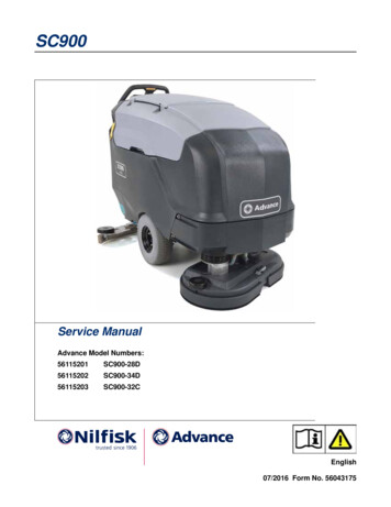
ANCHORSFRAME ANCHOR INSTALLATIONSkirting/Side WallStep 1Step 2Step 31. Position anchor at a slight back angle (10 ) so that when fully installed, the anchor head will be inside anyskirting or side wall.2. Install anchor to /- 2/3 depth, then install stabilizer vertically, within 3 in. - 4 in. of anchor shaft, parallel towall of home. Fully drive anchor down the anchor head.3. Attach strap (see proper strap tensioning), and pretension strap to pull anchor rod against the stabilizer plate.Manual Anchor Installation1. Dig holes to a depth of 2/3 of the anchor length. Install anchor with rod or length of pipe for leverage.2. Replace earth in hole after anchor/plate is installed at full depth. Pack dirt with a tamping rod every 6 inches of fill.3. Testing may be required in loose soil conditions to check that anchor has proper holding power.IMPORTANT!Anchor must be installed to full depth. Anchor head must be at ground level or at the top of thestabilizer plate which is fully installed to ground level.6605 Stonehill Drive SW Atlanta, Georgia 30336 404.344.0000 www.tiedown.com
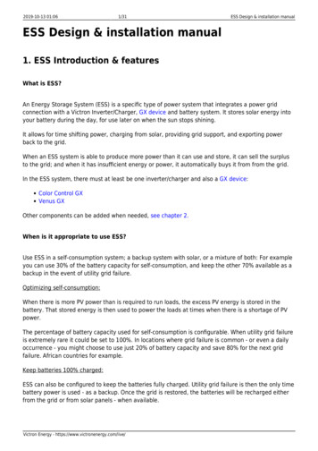
ELECTRIC DRIVE MACHINEELECTRIC DRIVE MACHINE INSTALLATIONOperation InstructionsAdapterHead1. Attach adapter headto shaft of the EDM motor,tighten set screw.GFI SwitchOperating Instructions:Motor ShaftExtension HandleSet ScrewAnchor AdapterHeadOperation InstructionsSafety PinHole1. Attach adapter head to shaft of the EDM motor, tightenset screw.Motor ShaftAttachrecommendadapter head to2. It may not be needed but it is1.highlyto shafttheEDM motor,attach the handle2.extension.theIt may not beUsingneededbutofithandleis highlyrecommend to attach theextension increases setextension.Usingthescrew.handleextensionAnchor Adapterstrength during installation.stability while reducing muscle strengthHeadduring installation.3. Plug in the drive machine. Electrical cords must be a minimum 12-2 cordup to 50’, 10-2 cord over 50’. Recommended minimum 1500w generator.4. The GFI will shut off power when a ground fault isdetected. The GFI3. willpower when itPlugalsoin theshutdrivemachine.2. Itoffmaynot be needed but it is highly recommend to attach thedetects low voltageimproperrequiredto drivecord up to 50’, orElectricalcordsampsmusta minimumhandle beextension.Using12-2the handle extension increasesthe motor. Many timestheproblemwillbetheuseof an10-2 cord overstability50’. while reducing musclestrengthextension cord thatistoolongoristoolightingage. Recommendedduringminimum1500wgenerator. Never operate without the factoryinstallation.installed GFI(Ground Fault Interrupter) power cord.4. The GFI will shut off power when a ground fault is detected.The GFI will also shut off power when it detects lowCALL BEFORE YOU DIG. DIAL 811voltage or improper amps required to drive the motor.Before installation of any ground anchor, determine thatMany times the problem will be the use of an extensionthe ground anchors to be installed will not be near anycordcables,that is toophonelong or islines,too lightwaterin gage. lines,under ground electrical rivemachine.sewer pipes, or gas lines. Failure to do so may resultinGFI(GroundFaultInterrupter)powercord. Electricalcordsmustbeaminimum12-2 cord up to 50’,serious injury or death.10-2 cord over 50’. Recommended minimum 1500w generator.4. The GFI will shut off power when a ground fault is detected.The GFI will also shut off power when it detects lowvoltage or improper amps required to drive the motor.Many times the problem will be the use of an extensionSet ScrewSafety PinSafety PinHoleHolePress “Reset” if the motorfails to run. Ground Faulthas interrupted thepower supplySafety PinHolePress “Test” to checkthe power interrupt isworking “No Power”Press “Reset” if the motorfails to run. Ground Faulthas interrupted thepower supply7Press “Test” to checkthe power interrupt isworking “No Power”
Operation Instructions CALL BEFORE YOU DIG. DIAL 811Before installation of any ground anchor,determine that the ground anchors to beinstalled will not be near any under groundelectrical cables, phone lines, water lines, sewerpipes, or gas lines. Failure to do so may result inserious injury or death.ELECTRIC DRIVE MACHINE5. Place anchor tip in location where anchor is to be5. Place anchor tip in location where anchor is to be buried.buried. The Electric Drive Machine (EDM) is designedThe Electric Drive Machine (EDM) is designed forfor operation by two people. Hold anchor in place at theoperation by two people. Hold anchor in place at thedesired installation angle.desired installation angle.6. Place anchor head into adapter, line up anchor shaft6. Placeanchor head placeinto adapter,line pullup anchor shaft withwith EDM shaft. For easierinstallationa 1/2”EDMshaft.Foreasierinstallationplacepin or a slotted bolt though the adapter head (Safety a 1/2” pull pin or aslottedbolt thruthe theadapter(Safety Pin Hole) andPin Hole) and anchor lpin/boltbolt comes out the other side. This will prevent the EDMcomes out theside. This will prevent the EDM from separatingfrom separating from the otheranchor.from the anchor.7. Flip forward/reverse switch to forward.7. Flip forward/reverse switch to forward.8. Hold the power switch on until anchor reachesproper depth. The powerspringIf reaches8. switchHold the ispowerswitchloaded.on until anchoryou encounter any problems release the switch and theproper depth. The power switch is spring loaded.machine will shut off automatically.If you encounter any problems release the switchand the machine will shut off automatically.Electric Drive Machine Cautions and Warnings:ForwardReversePower Switch404-344-0000 tiedown.com605 Stonehill Drive SW, Atlanta, GA 30336 Before installation of any ground anchor, determine that the ground anchors to be installed will not be near anyunderground electrical cables, phone lines, water lines, sewer pipes, or gas lines. Failure to do so may result inserious injury or death The EDM is designed for operation by two people. Do not allow the EDM to be wedged against the home or other solid objects, when operating the EDM. Electrical cord must be a minimum of 12-2 wire size w/ground up to 50 ft. Longer cords should be 10-2 wire sizewith ground. Never operate the EDM in wet or rainy conditions. Frayed or patched electrical cords should never be used with the EDM. Care should be taken to keep electrical cords away from anchors. Never operate drive machine without the GFI power cord. Damage to motor and injury to operator can r esult fromby passing the GFI.8605 Stonehill Drive SW Atlanta, Georgia 30336 404.344.0000 www.tiedown.com
STABILIZERSANCHOR STABILIZERSIn order to prevent lateral movement of manufactured homes subjected to high wind loads and to comply with HUD’sWind Zone I, II, & III requirements, all lateral frame ties must be attached to a properly stabilized ground anchor.(Two approved methods illustrated below.)12” wide Stabilizer PlatePainted BlackGalvanizedPart ID: 59292Part ID: 59292GClass 4B Stabilizer Plate17-1/2 in. x 13-1/2 in.GalvanizedPart ID: 59286STABILIZER PLATE INSTALLATION1. Refer to any and all local, state and federal regulations.2. Use the Soil Test Probe at the anchor location in order to match soil class with the anchor/stabilizer(see page 16).3. Partially install anchor to allow 14 in. to 16 in. remaining above ground level.4. Utilizing oversized hammer, vertically install stabilizer plate, nesting anchor rod in between formed channels onoutside of stabilizer plate (between anchor and frame).5. Fully install anchor so that head is at the surface of the soil (1” tolerance, if necessary) and pretension anchoruntil touching stabilizer plate.Ground Level"In Line" Installed:Minimum anchorlength of 36"9
STABILIZERSABS STABILIZER PLATEPart ID: 592931. Determine correct anchor to be used with the homeinstallation and use the manufacturer instruction forinstallation, following all safety precautions.Place ABSPlate Here2. Using an electric drive machine, install anchor to a depth ofapproximately 28 inches at a slight back angle.3. Dig out an 8” wide area so that the ABS stabilizer will beplaced on undisturbed soil at a 10 to 15 degree angletoward the home. The bottom center of the plate should betouching the anchor rod.4. Complete the installation of the ground anchor until thebottom of the anchor head is flush with the ground.Tamp SoilIn 6" increments5. Attach proper strap and tension strap until anchor head isflush against the ABS plate and strap is tight. At this point,soil should be tamped into the vacant area behind theanchor rod, tamping approximately 6” and repeating untilthe vacant area is flush with the surface of thesurrounding ground.QUIK-SET STABILIZER INSTALLATIONBlack PaintGalvanizedPart ID: 59291Part ID: 59291G1. Install ground anchor inside skirting line at a slight backangle of 10 - 15 .10 -15 2. While anchor head is still 5 in. to 6 in. above ground level:install Quik Set stabilization plate around anchor shaft,referring to the direction imprinted on the top of the plate.5" to 6"3. Install ground anchor until Quik-Set plate is fully set.Hammering may be required at the corners to insure platebeing fully driven.HomeDirection4. Install strap(s) to anchor head and pretension according toapproved methods. Maximum anchor load in conjunctionwith the “Quik-Set” device is 4725 lbs. (ultimate).10605 Stonehill Drive SW Atlanta, Georgia 30336 404.344.0000 www.tiedown.com
STRAPCERTIFIED GALVANIZED STRAPPINGDescriptionLengthPart ID:G60 StrapG60 StrapG60 StrapG60 StrapG120 StrapG120 Strap35 ft.37 ft.60 ft.600 ft.37 ft.600 ft.591505915559165591705921859219DOUBLE THICK G-60DOUBLETHICK G-60GALVANIZEDPROTECTIONGALVANIZED PROTECTIONTIE DOWN ENGINEERINGCERTIFIEDTOENGINEERINGTIE DOWNANSI A225.1 ASTMD3953-97CERTIFIEDTOANSI A225.1 ASTM D3953-97The steel strapping by Tie Down for the manufactured housing industry has been tested to, and conforms to, theHUD Code as referenced in Part 3280 of the Manufactured Home Construction and Safety Standards and Part 3285of the installation standards; Final Rule.3280.306(f), 3285.402(b2) Anchoring Equipment – Load Resistance. Anchoring equipment shall be capable ofresisting an allowable working load equal to or exceeding 3,150 pounds and shall be capable of withstanding a 50percent overload (4,725 pounds total) without failure of either the anchoring equipment or the attachment point on themanufactured home.3280.306(g), 3285.402(b2) Anchoring Equipment – WeatherizeAnchoring equipment exposed to weathering shall have a resistance to weather deterioration at least equivalent tothat provided by a coating of zinc on steel of not less than 0.30 ounces per square foot of surface coated, and inaccordance with the following:(1)(2)DOUBLEGALVASlit or cut edges of zinc-coated steel strappingdo not need to be zinc coated.NIZ THICKEDG-60Type 1, Finish B, Grade 1 steel strapping, 1-1/4PROincheswide and 0.035 inches in thickness, certified by aTECTIONTIE with ASTM Standard Specification D3953-97,registered professional engineer or architect as conformingDOWANSI A CER N EN225 TIF GINStandard Specification for Strapping, Flat Steel, and Seals.1 A IED EERSTM TO INGD3953-97The above specification of a minimum coating of 0.30 ounces per square foot equates to a designation of “G30.”Tie Down strapping exceeds this minimum requirement with a coating of 0.60 (G60) or 1.20 (G120) ounces as perabove. Similarly, Tie Down strapping exceeds, in testing, the minimum load requirements of 3,150 pounds design(working) load and 4,725 pounds (ultimate) overload.CRIMPING SEALSTIE DOWN ENGINEERINGCERTIFIED TOANSI A225.1 ASTM D3953-97Part ID: 59175To lengthen strap in the field, a double crimp sealsplice is required. Overlap strap approximately 12inches and use two crimp seals evenly spaced, with2 crimps per seal.One crimp seal is used when strap is attached to asidewall bracket ora strap connector. If the brackTIEDOWNANSI AaCEradiusEet does not haveedge, a radius clip (short225 RTIF NGIN.1 IED EERSTM TO ING“U” shaped piece of Astrap)must be placed betweenD3953-97the strap and contact pointto protect the strap fromsharp edges. Verify state requirements for numberof crimp seals required.TIE DOWN ENGINEERINGCERTIFIED TOANSI A225.1 ASTM D3953-972 Seals - 2 Crimps Per SealFile name "strapping2.name "strappin1 FileSeal - 2 Crimps11File
12-15 inchesSTRAP12-15 inchesCutPROPER STRAP TENSIONINGCutStep 1Insert slotted bolt into anchor head, attach loosely. Pullstrap past bolt head and cut strap so that 12-15 inchesof strap are available to wrap onto the slotted bolt.Step 2Insert the strap end into the slot in bolt until flush withopposite side of bolt.12-15 inches12-15 inchesCutCutStep 3Using 15/16” wrench or socket, turn the bolt, windingthe strap so that a minimum of four to five completeturns are made, and the strap is adequately tensioned.Step 1Step 2Step 3Step 4Step 4Hold the bolt under tension while tightening the nut,drawing the head of the bolt into the recess. After thebolt is within the recess, continue to tighten the nutuntil securely fastened.STRAP TENSIONING - SPEED WRENCHPart ID: 48900Tie Downs SPEED WRENCH simplifies anchor installation witha design that allows for one handed operation for installingslotted bolts and tensioning strap. The SPEED WRENCH hasa 15/16 in. impact socket on one side and a 15/16 in. “nut” onthe other. Combine this with your own ratchet and 15/16 in.socket and you have the fastest way to tighten slotted bolts!Step 1Place Speed Wrench over the bolt head. Insert the strap endinto the slot in bolt until flush with opposite side of bolt.Step 2Hold Speed Wrench in place, tighten bolt with socket wrenchon outside of Speed Wrench (bolt head side).Step 3Move socket to the opposite (nut) side. Hold Speed Wrench inplace. Use socket wrench to tighten nut.12605 Stonehill Drive SW Atlanta, Georgia 30336 404.344.0000 www.tiedown.com
STRAPFRAME TIE TO ANCHORIf this angle exceeds 60 , anadditional frame tie must beattached to the opposite beamas indicated by the dotted line.A Stabilizer Plate must be installedon all frame Ties. (or alternate methodof stabilizing ground anchor.)Select proper anchor for soilconditions using the Soil TestProbe, or other approved methodof determining soil classification.Frame withStrap"I" Beam FrameIf this angle exceeds 60 ,See Note BelowGround LevelShown withHookAlternative set to avoidcrushing “Bellyboards” ,with manfuacturers approvalSTRAP PROTECTORSFor protecting Vertical and Diagonal Strapping at sharpcorners when wrapping the top and bottom of the beam.Step 1Attach hook between strap and I-beam and fold perforatedlip around the beamStep 2Fold the middle table down bending around the I-beamleaving 2 legs to guide the strap into position.Step 3Feed the strap over the I-beam though the two legs on thestrap protector.13
STRAPFRAME TIE WITH HOOKStep 1Attach frame hook to top inboard location of I-beam.Step 2Keeping in line with the hook, wrap galvanized strap completely aroundI-beam. Strap protectors may be installed on bottom of the I-beamStep 3Thread loose end of strap through slotted tensioning bolt attached totension head of anchor. (Anchor must be properly installed into theground before proceeding with step #4.)Step 4Tighten slotted tensioning bolt a minimum of 4 to 5 full turns until all slackin strap is removed.FRAME TIE WITH BUCKLEStep 1Install strap by pushing the end between the inside of the frame “I” beam and thefloor.Step 2Position the buckle at upper end of the “I” beam frame. Wrap the end of the straparound the “I” beam. Thread the end of the strap through the slot in the buckle asshown. Push the end of strap in-between “I” beam and floor.Step 3Pull the strap, making certain the buckle stays in position. Thread loose end ofstrap though slotted tensioning bolt attached to tension head of anchor. Tightenslotted tensioning bolt a minimum of 4 to 5 full turns until all slack in strap isremoved.STRAP BUCKLE - MBUStep 1Thread length of frame tie strap through strap buckle as shown.Step 2Next, thread long end of strap between frame and floor of home.Bring strap through buckle as shown in diagram and fasten toanchor head.Step 3Diagram shows strap in position around frame and throughbuckle. It is important to remove all slack from system.14605 Stonehill Drive SW Atlanta, Georgia 30336 404.344.0000 www.tiedown.com
STRAPSWIVEL STRAP CONNECTORSBeam Method:Step 1In order to assure adequate compliance refer to all local, State,and Federal Regulations, as well as manufacturer’s recommendedtie down method.SwivelConnectorStep 2Frame ties attach to the beam with a swivel frame connectorplaced over the top of the beam. The hook end of the connectorshould be snug against the beam. Longitudinal ties would attach toGator clamps bolted to bottom of the beam.Step 3Attach the swivel connector to the underside of the flange andframe hook or bracket with a 1/2” grade 5 nut and bolt. This allowsswivel to pivot and lock onto I-beam.Step 4Pull strap past anchor head 12 to 15” and cut strap. Thread theend of the strap through the slotted tensioning bolt attached to theHomeHometensioning headfor the anchor.Tighten slotted tensioning bolt4 - 5 full turns until all slack is removed and strap is tight.Beam ClampI BeamI BeamSwivelConnectorGator ClampUniversal Strap ConnectorHomeSidewall & Longitudinal SlottedInsert strap connector at a 45 degree angle.Return to 90 degree angle, pull down andattach to ground anchor. (Slotted connectionsmust be straight pull. Bolted connections canhave 15 degree max. angle.)HomeHomeSidewallHomew/Nut & BoltAttach strap connector to sidewall connector withnut & bolt, then attach to ground anchor.15
STRAPGATOR BEAM CLAMP4 Bolt Gator Clamp (Wind Zone 1, 2 & 3)8 Bolt Gator Clamp (Wind Zone 3 - and Florida)Part ID: 58999Part ID: 59011Step 1Determine anchor/stabilizer plate location and bracket locationon I-beam to insure a 45 or lower strap angle.Step 2Attach beam clamp with 1/2 in. Grade 5 bolts and nuts as shown.Step 3Connect swivel connector and strap to bolt nearest to anchorwith a 1/2 in. Grade 5 bolt and nut.I-beamFactory LongitudinalBracket or Gator ClampPier60 LongitudinalStrapAnchor withStabilizerPlateNOTE:Gator Beam Clamps mustbe attached with a SwivelStrap Connector #59002.1 Strap for Wind Zone I2 Straps for Wind Zones II & IIIANGLE FRAME BRACKETPart ID: 59009Step 1Determine anchor/stabilizer plate location and bracketlocation on I-beam to insure a 60 or lower strap angle .Step 2Drill a 1/2” hole, centered in the I-beam as shown. Holemust be a minimum of 4” from any edge of the I-beam.Step 3Connect the two Frame Brackets (R & L) with a 1/2” Grade 5bolt and nut for Wind Zone II & III and one frame bracket rightor left for Wind Zone I.Step 4Attach swivel connector and strap to Angle Frame Brackets with1/2” Grade 5 bolts and nuts. Tighten all bolts.16NOTE:Gator Beam Clamps mustbe attached with a SwivelStrap Connector #59002.605 Stonehill Drive SW Atlanta, Georgia 30336 404.344.0000 www.tiedown.com
ANCHORSDEEP SET ANCHOR/STABILIZER rtPartID:ID:ID:ID:59091596645909259665NOTE:45 maximum (if angleexceeds 45 attachadditional strap tie toopposite frame)Wrap strap onto tensionbolt (minimum 4-5 turns)Class 3Class 4A1. Confirm soil classification using standard torque probe at proper depth below ground surface, make certainreadings meet or exceed torque readings for Class 2 and 3 soils at the depths of 30 in. & 36 in.2. Clear loose vegetation where anchor will be installed. Install anchor vertically to its’ full depth. Stabilizer plate atthe top of anchor must be fully embedded into soil.3. Pull strap past anchor head and cut strap so that there is 12 in. to 15 in. of strap to wrap onto anchor bolt insuring4 to 5 wraps minimum.4. Insert strap into anchor bolt flush with opposite side of bolt. Tighten bolt/strap until tight. Secure anchorbolt with nut.ASPHALT ANCHOR INSTALLATIONPart ID: 59367For horizontal anchorage at a maximum of 50 degrees, not forvertical anchorage.1. Using a masonry or similar abrasive blade in a circular saw,cut a slot 8” long x 1 ½” deep in the asphalt where the anchoris to be installed with the plates of the anchor parallelto the structure.2. With a 5/8”masonry bit installed in a hammer drill, pre-drill ahole approx. 12” deep
5 ANCHOR CHART Soil Class & Recommended Part ID: Test Values (in. lbs.) Anchor / Stabilizers Black Galvanized 30 in. Cross Drive Rock Anchor4b 59110N/A276 to 350 48 in. Cross Drive Rock AnchorBlue 59111N/A 30 in. x 5/8 in. rod / 2 - 4 in. helix 5909059078 30 in. x 3/4 in. rod / 2 - 4 in. helix 5909559079 60 in. x 3/4 in. rod / 2 - 4 in. helix 5909759097G