Transcription
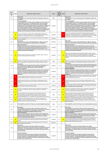
ANNALS of the ORADEA UNIVERSITY.Fascicle of Management and Technological Engineering, Volume VI (XVI), 2007ENVELOPE REQUIREMENT VERSUS PRINCIPLE OF INDEPENDENCYCarmen SIMION, Ioan BONDREAUniversity "Lucian Blaga" of Sibiu, Faculty of Engineering “Hermann Oberth”,e-mail:carmen.simion@ulbsibiu.ro, ioan.bondrea@ulbsibiu.roKeywords: principle of independency, envelope requirement, tolerance inspectionAbstract: To ensure quality of technical goods and their production and assembly processes, regarding thefunction of each part, the designer sets its dimensions and other characteristics and also their tolerances. Inthis context, the international standardisation defines several principles and good practices for specifyingtolerances. In this paper a definition of tolerance specification is given, the relationships between thedifferent tolerance systems: the principle of independency and envelope requirement are explained andsome applications of these tolerancing principles are introduced.1. TOLERANCE SPECIFICATIONRegarding the function of a part, the designer sets its dimensions and othercharacteristics in a complex process by using his creativity, experience and knowledge.Additionally the designer defines the manufacturing route and the quality assessment ofthe components. The questions the designer initially is posed with during the designconstruction, deal with successfully fulfilling function of the component. A drawing whichdoes not conform to the basic needs in a “complete” and “defined” manner can not beused as a basis for production and quality control.Since the dimensions or other characteristics of a part cannot be exactly realized inmanufacture, it must be given some kind of limit values, either on the drawing (preferably)or by reference to another document containing such limit values. These stipulate thevalues according to which the parts are to be approved or rejected. So, to ensure quality oftechnical goods and their production and assembly processes, the dimensions and theproperties have to be limited and therefore toleranced. Tolerances are a communication ofdesign, manufacturing, and inspection intent. Tolerance specification is here taken tomean each specification whereby the permissible variation for any property is given fixedlimits. A tolerance specification includes those values which determine the limits fordimensions or other property. The tolerances shall be chosen so that they correspond tothe functional and/or economical rejection limits.In all cases, tolerances apply to features which are geometrical elements of a part,such as: lines, planes, circles, cylinders, cones, spheres, helixes, tore, and mathematicallydefined curves and surfaces (profiles). The main characteristics of a feature and ageometry are its size, form, orientation, and location. Size tolerances are referred to asdimensional tolerances, while form, profile, orientation, location and run-out tolerances arereferred to as geometric tolerances [1] [4] [5].Several principles and good practices for specifying tolerances are either explicitlydefined or implied in the manufacturing tolerance standards. The principles help to ensurethat: the functional, manufacturing and inspection intents are clear, the individualspecifications form a consistent set of specifications with clear intent and priority, thespecifications are realistic in the sense that they are producible and measurable, andunnecessary accumulation is minimized.So, during the process of defining the tolerances of single parts or groups ofcomponents, according to ISO 8015, it must always be decided if the independenceprinciple can allow for a toleranced size or if the envelope requirement has to be used.Additionally it must also be decided if a deviation of form or orientation, location or run-out1256
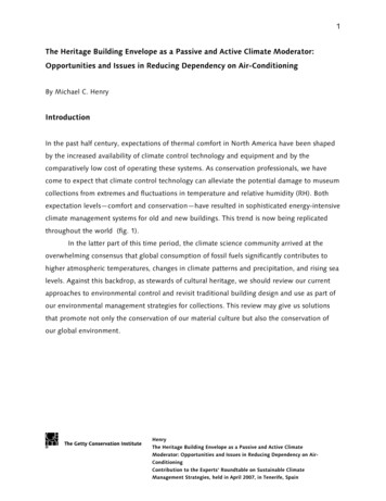
ANNALS of the ORADEA UNIVERSITY.Fascicle of Management and Technological Engineering, Volume VI (XVI), 2007has to be stated independently or if the maximum material requirement, minimum materialrequirement or reciprocity requirement can be allowed for certain geometrical tolerances.Beside the previously discussed principles of tolerancing, other conditions like theprojected tolerance according to ISO 1101 or the free state according to ISO 10579 areused in technical drawings (Fig.1) [1] [3].Figure 1. Principle of tolerancing for geometrical tolerances (ISO 1101) [1]In describing different kinds of sizes, the mating of components was pointed out severaltimes. Mating of components is one of the main reasons for tolerancing. Only by givingtolerances and calculating the relationship between all the geometrical features couldinterchangeable manufacture in its modern form be made possible. Due to the fact thatdifferent nations had different standards for tolerancing in use, different interpretations ofone drawing were possible. The ISO published the standard ISO 8015 in 1985, whichshould harmonize the tolerancing. With the introduction of ISO 8015 a clear correlationbetween tolerancing deviations of form, location and those of size (mainly at cylindrical, flatand parallel mating surfaces) was defined.2. PRINCIPLE OF INDEPENDENCYEach specified dimensional or geometrical requirement on a drawing shall be metindependently of other requirements, unless a particular relationship is specified. This isthe fundamental principle of tolerancing and it is named the “principle of independency” [3].Therefore, where no relationship is specified, the geometrical tolerance applies regardlessof feature size and the two requirements are treated as being unrelated. Consequently, if aparticular relationship of size and form (see the envelope requirement), or size andlocation, or size and orientation is required, it shall be specified on the drawing.When reference to the principle of independency is made on the drawing, the dimensionaltolerance, regardless of whether it is expressed as a numerical tolerance or an ISOtolerance, does not control the form if the form deviation is such that it will not be detectedby two-point measurement.In conclusion, dimensional tolerances do not limit form deviations unless such a limitationis specified in the tolerance requirement:1257
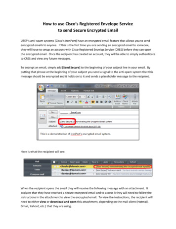
ANNALS of the ORADEA UNIVERSITY.Fascicle of Management and Technological Engineering, Volume VI (XVI), 2007a)A linear dimensional tolerance controls only the actual local sizes (evaluated bytwo-point measurement) of a feature (a cylindrical surface or two parallel plane surfaces),but not its form deviations (for example circularity and straightness deviations of acylindrical feature or flatness deviations of two parallel flat surfaces.)Form deviations shall, however, be controlled by the geometrical tolerances or enveloperequirement.There is no control of the geometrical interrelationship of individual features by the lineartolerances. For example, the perpendicularity of the sides of a cube is not controlled and,therefore, it requires a perpendicularity tolerance dictated by the function requirement.b)An angular tolerance, specified in angular units, controls only the generalorientation of lines or lines on surfaces, but not their form deviations. The generalorientation of the line derived from the actual surface is the orientation of a contacting lineof ideal geometrical form. The maximum distance between the contacting line and theactual line shall be the least possible value.Form deviations are controlled through geometrical tolerances.Geometrical tolerances are used to control form, orientation and/or position on real orabstract features, regardless of the feature size.The geometrical tolerances will, therefore, apply independently of the actual local sizes ofindividual features. The geometrical deviations may be at a maximum whether or not thecross sections of the respective features are at maximum material size. For instance, ashaft with maximum material size at any cross-section may have a lobed form deviationwithin the circularity tolerance, and may also be bent by the amount of the straightnesstolerance, see figures 2a and 2b [3].Tolerancing principle ISO 8015a)Maximum limitof sizeMaximum circularitydeviation (resultingfrom a lobed form)Maximum limitof sizeMaximumstraightnessdeviationEach cross-sectionb)Figure 2. Principle of independency: a) Drawing indication; b) Interpretation [3]1258
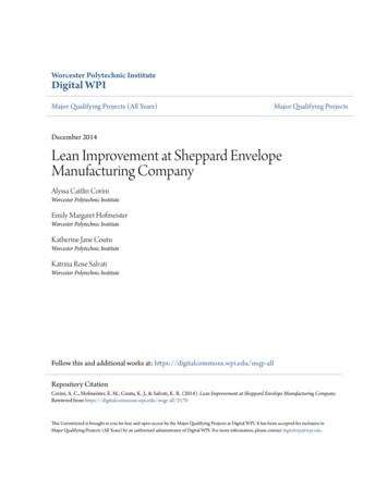
ANNALS of the ORADEA UNIVERSITY.Fascicle of Management and Technological Engineering, Volume VI (XVI), 2007If the principle of independency is used at a hole, checking involves proving that all localtwo point measurements are within the limits of size. Deviations of form and parallelismare not globally limited by the principle of independency, except for the barrel form, thesaddle form, the cone form in axial section and the even-numbered polygons in a radialsection (e.g. oviform). Further bends and uneven-numbered polygons (e.g. n lobed) arenot limited. During the construction phase it is generally not obvious which deviationsproduction might cause. This is why in certain cases geometrical tolerances have to be setout of functional reasons as well as tolerances of size.The principle of independency should be used generally for features, which are not to bemated.On the drawing the fundamental principle of tolerancing is be indicated by the note“Tolerancing principle ISO 8015". The note shall be placed above the title block.3. ENVELOPE REQUIREMENTThe linear and geometrical tolerances are independent of each other, which mean that thegeometric tolerances apply regardless of the feature size. The geometrical deviations maybe at maximum whether or not the cross-sections of the respective features are atmaximum material limit/size (the size of the smallest permissible hole or the size of thelargest permissible shaft respectively). This is true unless a particular relationship hasbeen specified. If there is a need for mutual dependency of size and geometry, the“envelope requirement” or the “maximum material principle” can be used [3].The envelope requirement - on the drawing is noted with the symbol E - establishes arelationship between size and form, and the maximum material principle - on the drawingis noted with the symbol M - establishes a relationship between size and form, orientationor/and position (Fig.3)So, the envelope requirement is based on the dependency between the form of a featureand its actual local size and it states that the real feature must not exceed the geometricalideal envelope with the maximum material limit within the mating zone. The real size hasto be as far away from the maximum material limit, as the expected deviation of form willbe. In practice, the application of the envelope requirement means that if the actual size ofthe feature deviates from the maximum material limit, the form deviations are allowed to belarger.SizeFormOrientationPositionEMFigure 3. Application of the independence principle and the envelope requirement1259
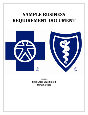
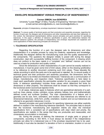
ANNALS of the ORADEA UNIVERSITY.Fascicle of Management and Technological Engineering, Volume VI (XVI), 20070Ø150 h7 (-0,04)The envelope requirement may be applied to a single feature, for instance a cylindricalsurface or a feature established by two parallel flat surfaces. The envelope requirement isused for features which are to be mated.The envelope requirement may be indicated either by the symbol E placed after thelinear tolerance (Fig. 4,a) or in relevant cases by reference to an appropriate standardwhich invokes the envelope requirement. This applies regardless of if the tolerance hasbeen indicated as a numerical tolerance (with deviations) or by means of an ISO symbol.Figure 4,a shows an example of the envelope requirement applied to a cylindrical feature.The function requirements are [3]: the surface of the cylindrical feature shall not extend beyond the envelope of perfectform at maximum material size of Ø150; no actual local size shall be less than Ø149,96.Tolerancing principle ISO 8015a)Envelope of perfect form atmaximum material limitd1, d2 and d3 – actual local diametersActual localdiametersb)c)Envelope of perfect form atmaximum material limitEnvelope of perfect form atmaximum material limitActual localdiametersActual localdiameters,Ø 149,96d)e)Figure 4. Envelope requirement: a) Drawing indication; b,c,d,e) Interpretation [3]1260
ANNALS of the ORADEA UNIVERSITY.Fascicle of Management and Technological Engineering, Volume VI (XVI), 20070Ø150 h7 (-0,04)The drawing indication means that the actual part shall meet the following requirements: each actual local diameter of the shaft shall remain within the size tolerance of 0,04and may therefore vary between Ø150 and Ø149,96, see figure 4,b; the entire shaft shall remain within the boundary of the envelope cylinder of perfectform of Ø150, see figures 4,c and 4,d.Hence it follows that the shaft shall be exactly cylindrical when all actual local diametersare at the maximum material size of Ø150, see figure 4,e.On the drawings where the principle of independency is not applied (the note “Tolerancingprinciple ISO 8015" is not indicated), it is applied the envelope requirement for all thedimensional and geometrical tolerance (the envelope requirement is not indicated). In thiscase, the tolerances are interpreted in the following ways within the prescribed length:a)For holes: the diameter of the largest perfect imaginary cylinder which can beinscribed within the hole so that is just contacts the high points of the surface should notbe smaller than the maximum material limit of size. The maximum diameter at any positionin the hole must not exceed the least material limit of size.b)For shafts: the diameter of the smallest perfect imaginary cylinder which can becircumscribed about the shaft so that it just contacts the high points of the surface shouldnot be larger than the maximum material limit of size. The minimum diameter at anyposition on the shaft must not be less than the least material limit of size.The above interpretation mean
This is why in certain cases geometrical tolerances have to be set out of functional reasons as well as tolerances of size. The principle of independency should be used generally for features, which are not to be mated. On the drawing the fundamental principle of tolerancing is be indicated by the note “Tolerancing principle ISO 8015". The .