Transcription
www.dewesoft.com - Copyright 2000 - 2022 Dewesoft d.o.o., all rights reserved.CAN Bus and CAN FD Data Acquisition andAnalysis
Introduction to the Automotive busesVehicle subsystems from the internal combustion engine to powered windows are controlled by electronic control units(ECU). These units are usually dependent on each other and have to pass information between one another.For example, a control unit (CU) in the car's automatic gearbox shifts gears based on the engine revolutions per minute - RPMsand throttle position. The control unit in automatic transmission runs an algorithm that determines if the gear change isrequired based on the data that it gets from the engine control unit (engine speed - RPM, throttle position, emission sensors.).To ensure smooth gear shifting, engine speed has to be adjusted to the next gear. Therefore both control units have toconstantly communicate with each other to ensure correct operation.Another example is powered windows in a road vehicle. Their upward and downward motion is controlled by an ECU. Thiscontrol unit switches the electric motor in the correct direction and also stops the electric motor when the window is in thefully closed or fully opened position. The ECU gets messages to move windows from other control units. For example, it canget an order from a control unit that checks the position of dashboard buttons or from a unit that receives signals from avehicle remote control. Each of the mentioned control units performs its task and signals other control units to perform a taskthat is required from them. The messages can be sent in both directions. For example, the window control unit can send amessage back to other control units that the window is fully closed or fully opened.As we can see from the previous example a single unit works only if it is connected to other units. Message transfer betweenunits could be made with direct connections based on the dependency of electronic control units.Electronic subsystems on modern road vehicles are usually controlled by more than 150 ECUs. These control units are highlydependent on each other and are connected to a single or multiple serial networks.On a serial network, data is being transmitted bit by bit onto a network. Each device can read all of the messages on thenetwork but responds only to those that are meant for it. To ensure that critical messages get to their recipients with the leastpossible delay, message priority is based on message importance.1
Communication networks in modern road vehicles connect all of the electronic subsystems. With transfer speeds of up to 10Mb/s large amounts of data can be generated. With Dewesoft, we can decode and store this data.2
Supported Automotive Protocols in Dewesoft XEven though this PRO Training lecture is primarily focused on Controller Area Network (CAN) it is worth noting that DewesoftX supports other commonly used protocols in the automotive industry. The supported protocols are:Controller Area Network (CAN)A message based protocol, designed for automotive applications,native support in Dewesoft X,CAN interfaces available on different Dewesoft devices: DS-CAN2, DS-CAN4, DS-CAN8, DEWE-43, SIRIUS.Vector CAN hardware supported: CAN CARD X, CAN CARD XL, CAN CARD XLE, CAN CASE XL, CAN BOARD XL,VN7600, VN1630, VN1640, VN7610[Video available in the online version]FlexRayAutomotive network communication protocol,faster more reliable than CAN,more expensive then CAN, not widely used yet,available as Dewesoft X plugin,Vector FlexRay hardware supported: VN3600, VN7600, VN7610, VN7570, VN7572, VN8970, VN8972Fibex ( FIeld Bus EXchange) signal definition file supported.[Video available in the online version]OBD-IIVehicle On-board diagnostics (low sampling rate),provides access to various vehicle subsystem,only OBD-II on CAN is supported - some newer vehicles and all of those sold in US after 2008 have OBD-II on CAN. If avehicle is equipped with OBD-II on CAN diagnostics CAN High can be found on pin 6 and CAN Low on pin 14 of the OBDII connector.[Video available in the online version]3
XCP / CCPProtocol for ECU memory access with A2L definition file,available as a Dewesoft plugin,Supported protocolsCCP (Dewesoft CAN device required)XCP on CAN (Dewesoft CAN device required)XCP on ethernet (computer with ethernet port)[Video available in the online version]4
What is a Controller Area Network (CAN)?Controller Area Network (CAN) is the most widely used communication protocol in automotive applications. It was developedto replace complex wiring harnesses with a two-wire bus. CAN network consists of nodes in electronic control units (ECU) thatare connected on to a two wire bus. Any electronic device with a CAN interface can be connected on to a network.Messages on CAN aren't passed directly from node to node but are transmitted on to the network. Messages each have theirunique message identification number which is also used to determine message priority. CAN network can operate without acentral control node, message hierarchy is not based on nodes but on the messages that they transmit. Therefore, one nodecan transmit both high and low priority messages.Error in message transmission is checked by all of the nodes that are connected to the network. If one of the nodes detects anerror in message reception it sends a special error message on to the network. A node that originally sent the message has tore-transmit it.Different versions CAN configurations are defined by ISO standards. Normally there are two configurations used in automotiveapplications: High speed CAN is used for communications between critical subsystems that require high update rates anddata correctness (anti lock braking system, electronic stability control, airbags, engine control unit.). Data transfer speeds ofhigh speed CAN ranges from 1 kbit to 1 Mbit per second. Low speed CAN is used for fault tolerant systems that do not requirehigh update rates. Their maximum data transfer rate is limited to 125 kbit per second but their wiring architecture can be moreeconomical. In automotive applications low speed CAN is normally used for diagnostics, dashboard controls and displays,power windows.5
During CAN bus operation additional nodes can be connected on to it. Dewesoft devices with CAN interfaces act likeadditional nodes on the CAN network. Dewesoft devices can read and also write data on to the CAN network.6
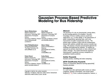
Which CAN message types do we know?There are four different message types/frames that can be transmitted on to the CAN network:Data frameData frame is a message that transmits data through the CAN network. It is the most common message type on the network.Message consists of:arbitration field - field that contains the message identification number and remote transmission request bit. Moreimportant messages have lower ID numbers. When multiple nodes want to transmit at the same time they start asimultaneous arbitration. A node with the lowest message ID number wins. The message identifier can be 11 bit(Standard CAN, 2048 different message identifiers) or 29 bit in length (Extended CAN, 537 million different messageidentifiers). The remote transmission request bit is dominant and signals that data is being transmitted,data field - field in length from 0 to 8 bytes that holds data,crc field - cyclic redundancy check field, shows if there were any mistakes during message transfer,acknowledge field - every node changes this field if it received a message without any errors .1.Image 7: Standard CAN data message versus Extended CAN data message2.7
Dewesoft X can read or transmit data frames. It only needs a message identification numbers and lengths of data fields ofeach data message. All of the other frames are automatically taken care of by Dewesoft devices and software.Remote frameThe purpose of the remote frame is to request a message from another node. By structure it is similar to the data frame. Thedifference is that it doesn't contain any data and has a recessive remote transmission request (RTR) bit which signals amessage request from another node.Error frameError frame is a special frame that violates CAN formatting rules and signals an error in data transmission. A node thatdetects an error while reading the message on the network transmits an error message. Because an error frame violates CANformatting rules all of the nodes that were reading from the network re-transmit it. After that a node that originally transmitteda message with an error has to re-transmit the original message.Overload frameIt is similar to the error frame with regard to formatting. It is transmitted by a node that becomes too busy. It is primarily usedas an extra delay between messages.8
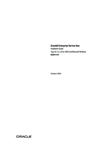
Dewesoft CAN device selectionDewesoft offers multiple devices with CAN interfaces. They all support CAN 2.0b input and output with a speed of up to1Mbit/s. All of the devices have a sync port installed for hardware synchronization with other Dewesoft devices.DEWE - 43Image 8: DEWE-43 is small and versatile device with 2 CANportspacked together with 8 analog and 8 counter inputsFor detailed information about the device you can check DEWE-43 product website.Dewesoft USB CAN interfacesFor detailed information about the devices you can check USB CAN interface products website. There you can find everythingabout the following devices:9
DS-CAN2SIRIUSim-4x-CANSIRIUSf-8x-CAN10
SIRIUS USB product lineCAN interfaces can be installed in instruments of the SIRIUS USB product line.11
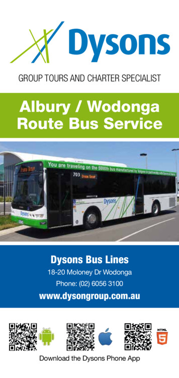
Inputs/Outputs CAN Configurations with DewesoftCAN configurations in Dewesoft X are going to be presented through an example with CAN input and output functionality. Torecreate this example and even access all of the CAN settings in Dewesoft X, a Dewesoft device with at least two CAN portsand a simple CAN bus are needed. An example is just a guide that is going to steer us through the available CAN settings inDewesoft X. You should still go through the next pages even if you don't have the required equipment.During the test one of the ports is going to transmit data the second port is going to read transmitted data from the network.CAN port on a Dewesoft device acts like a node on the CAN network. To connect both ports a simple serial bus has to beconstructed that connects CAN high and CAN low pins from one port to another. Connections have to be terminated with a120 Ohm resistor.12
Image 15: Test CAN setup schemeThrough the constructed bus Dewesoft math and user input channels are going to be transmitted from one port to anotherVirtual CANWithout a Dewesoft device a part of the measurement, mainly message and channel setup can be tested with CAN simulationin Dewesoft X. Virtual CAN can be used to make and verify CAN message setups offline, there is no data transmissionbetween virtual CAN ports.To set up virtual CAN ports go to Settings - Devices and pick Simulation as the Operation mode.Image 16: Change the Operation mode from Real measurement to Simulation modeAs it it shown on the Image 17, with a click on add button the window Add device will pop up. Here select the Test CAN (replaymode) option.13
Image 17: Add a Test CAN (replay mode) as a deviceTest CAN device number of ports, replay file and CAN plugin can be then configured in Device settings.Image 18: Virtual CAN device settings14
How to set CAN ports in Dewesoft X?To access CAN settings in Dewesoft X go to Settings - Devices and click on the a device with CAN ports that you have itconnected. In our example that is a DEWE-43 device that has two CAN ports. CAN ports should appear under the device info.CAN port settings can be accessed by right-clicking on the port that we want to configure. A context menu with availableoptions should appear after the right mouse click.CAN port baud rateCAN port baud rate on the Dewesoft device has to be the same as the baud rate of the CAN bus that we are connectingto. The default baud rate in Dewesoft X is 500 kbit/s this is more than enough for our example and there is no need ofchanging it.15
Enabling CAN outputWith the device connected we have to enable data transmission on one port. In this example we choose CAN 1 port andchange its operational mode from Read-only to Read/Write/Acknowledge.CAN pluginData transfer of some devices or some protocols is based on CAN messaging protocol. Messages from those devicescan be read in Dewesoft Xif we know which data is present in certain messages. With CAN plugins this is doneautomatically, where:OBD-II - Vehicle On-Board Diagnostics on CAN, plugin has standardized OBDII messages preconfigured. Additionalmessages can be added, the existing messages can be reconfigured.ADMA - plugin that supports Genesys ADMA (Automotive Dynamic Motion Analyser) an inertial measurement unitwith GNSS that is specialized for vehicle dynamics measurements. The device sends measured data in CANmessages but is configured through the COM port. Everything can be done in the plugin.CPAD2 - plugin for CPAD2 devices that run on CAN.Some additional devices or protocols that run on a CAN are supported with additional plugins (XCP Engine Control Unitmemory access protocol on CAN, Kistler Wheel force transducers with CAN interface, .). For our test example we are going togenerate our won messages and read them. Therefore, None of the plugins are needed.16
Acquisition loopThe maximum frequency of CAN output is dependent on the acquisition loop frequency of Dewesoft X software. Withperformance improvements of Dewesoft X the acquisition loop rate can be increased from standard 50 Hz to up to 1000Hz. This is necessary for CAN output test and can be done under Settings - Performance - Acquisition update rate.Image 23: Acquisition update rate setup17
How to make CAN channel setup?With connected and configured CAN device, CAN channel setup module can be added with a "More." button:In CAN channel setup you are going to find a setup screen for each of the CAN ports that are present on the connectedDewesoft device with a list of all the CAN messages and channels that are on the selected CAN port.18
NumberSettingDescription1J1939Changes CAN message decoding to J1939 standard. Messages on CAN bushave to be formatted according to J1939 standard, data messages have thesame length as extended CAN standard. Arbitration eld contains additionalsource and destination address. Baud rate is limited to 250 kbit/s or 500kbit/s depending on the J1939 standard version.CAN FDBus speedCAN port baud rate setting in kbit/s. Same setting as the device CAN portsetting.Error message count23Displays the count of error messages compared to correct messages presenton the bus.Store all messagesAll messages that are present on the CAN bus can be stored even if we don'thave them de ned in the message list. Stored CAN data can be decoded laterin CAN offline mode.ScanWith a bus scan turned on Dewesoft X recognizes CAN messages that arebeing transmitted on to a network.Search windowSearch for CAN channels according to their name or descriptionRx: Add read-only messageA button that adds a read-only message on to the message list. Read-onlymessages can be added in read-only and read/write/acknowledge mode.Tx: AddtransmitAdds a CAN message that is going to be transmitted by a Dewesoft device.This setting is available only if the selected CAN port is inread/write/acknowledge operational mode.messageDelete CAN messagetoDeletes a selected message independent of the message type.19
4Message/Channel ViewFilter Rx, Tx or Rx / Tx5View channels only or view both messages with belonging channels.Filter the view according to Read-only - Rx, Transmitting - Tx, or both Rx andTx messages.DBC, ARXML and XML CAN messages with channel definitions can be imported from DBC, ARXML orimport, DBC and XML XML les. DBC and ARXML les are common for CAN database de nition.exportXML has some additional info and is speci c to Dewesoft X. DBC and XMLformats can also be exported from CAN channel setup.20
How to define Math and User input channels?Math and User input channels can be defined in Acquisition mode under Channel setup.Math channelsDewesoft has many different data acquisition sources. Taking raw data measurement is often not enough to come to thewanted result, so data processing is one of the most important features t In Acquisition mode - Channel setup go to Mathchannel setup and add three new math formulas: Sine, Cosine and Square signal like it is shown on following Images 27, 28and 29.Formulas definition:Sine signal: add a new formula and name it 'Math Sine'. You can either click on sine function under Other Functions - Signals in Formula Options dialog and write the frequency of 10 Hz inside the sine function brackets, or you can just writesine(10) in formula syntax dialog.21
1.2.Cosine signal: name it 'Math Cosine'. It is similar to a sine signal but with a phase shift of 90Â that has to be written inRadians. Cosine formula syntax then looks like this: sine(10,0.5*pi).Square signal: name it 'Math Square'. Formula syntax for a square signal looks like this: square(10).22
User inputs channelIn channel setup click on More button add a User inputs channel.In User inputs channel setup add a channel and name it Value 0 100. For this channel set the time base as ASync and setchannel value limits on 0 for minimum and on 100 for maximum.23
How to define message Transmission?24
How to define Read only message?Message/Channel list on CAN port 0 is now fully populated with CAN transmission channels. To receive these channels, wehave to define what messages and channels are going to be received by CAN port 1 which is in read-only mode.If we want to receive the messages that are being transmitted, we have to define read-only messages and channels on CANport 1 with the same formatting as the transmitted channels on CAN port 0 . This can be done manually or with a messagecopying from one port to another.Manual channel definitionsDefinition of read-only messages is fairly similar to transmission message definitions. To define a new channel a new readonly message has to be added. For the correct reception of data read-only messages have to have the same setup in terms ofCAN message formatting, message ID, and message data field structure.25
As we can see on Image 41 there is no message scheduling but there is a time delay if we want to compensate CANdelay when we are storing the data. Transmit delay is nicely shown in the chapter 'How to measure with CAN channels?'.In channel setup there is no need to define channel value. There is an additional option regarding channel signal type whichoffers three options: Regular signal, Multiplexor signal, and Multiplexed signal. This is an additional option that enables thereception and identification of different variables in CAN messages with the same message ID as data channels on their own.Message copyingMessage and channel copying is implemented in CAN channel setup to avoid mistakes and reduce the time required whensimilar channels are being defined. Either messages or channels can be copied. Copying works even from one CANport to another.For our example a specific form of copying from port to port exists that enables quick read-only message definition by copyingtransmit messages on to the second CAN port and swapping message property from transmission to read-only.26
If read-only channels are properly de ned, the CAN 1 port (Read-only CAN port) should receive the messages transmitted fromthe CAN 0 port (Read/Write/Acknowledge CAN port). This can be seen in the CAN message/value channel setup. In thefrequency column, an approximate frequency of periodically transmitted channels should appear, also the bit value in the Valuecolumn should change values.27
How to set up the Measurement screen?In CAN channel setup we can see that there is no message transmission of the User input channel "Value 0 100". The reasonfor it is that it is transmitted only when a user clicks on a visual control that has a User input channel defined on it. This wasdefined in the CAN message setup where message scheduling was set to the "On button" option. For this to work themeasurement screen has to be properly set up.Go to the Measure tab and the enable Design mode as it is shown on the Image 44. In design mode add two displays whereone will be used to view channels that are transmitted periodically - Recorder display and one will be used to monitor the userinput channel - Input control display, where changing the value of the User input channel is possible.The "Input control display" settings have to be changed. And the user input channel "Value 0 100" has to be assigned to theInput control display visual control. "Input control display" should be set to the "Control channel" display type with the "Controlchannel" set to "Vertical slider". Slider minimum and maximum should be changed from 0 to 100. To assign the user inputchannel to the slider with the slider selected click on the User input "Value 0 100" channel in the channel tree view on the right.28
29
How to measure with CAN channels?After everything is set up we can proceed with the measurements and compare math channels with those that are read fromthe CAN bus.Sine and cosine signalWe can compare the original math sine signal with the received sine signal from the CAN network. It can be seen that thereceived sine signal isn't as accurate as the generated math signal. That is a consequence of 10 ms periodic messagescheduling (approximate asynchronous rate of 100 Hz), one period of a sine signal with 10 Hz frequency is represented by 10samples that were read from CAN. The received signal is asynchronous, even with the lowest arbitration ID of the messagethat carries sine and cosine data the message cannot be transmitted if the network is full (another node is in the middle ofmessage transmission). Received signal has a delay between 7 and 8.5 milliseconds. This delay is caused by the dataconversion and transmission, because at rst, a new math channel value has to be generated packed into the CAN messagetransmitted through the network, decoded, and then stored in Dewesoft X.Timestamps from sine and cosine signals that were received through the CAN network are equal. Sine and cosine samplescame in together with the same CAN message.30
Square signalWe can see that a CAN message with the square signal isn't sent at the exact frequency of 100 Hz (periodic scheduling on 10ms) the transitions of generated and received signal aren't equally spaced.31
User input channelThe User input channel is transmitted only when a user clicks on a slider, this can be seen on the recorder.32
33
What are DBC, ARXML and XML configuration files?As mentioned on the channel setup page, the CAN channel setup can be imported from DBC or XML files.DBC and ARXMLles are commonles for de nition of CAN messages and signals. Both formats contain only theinformation needed to decode messages and signals on the bus. Because of that both formats do not support transmissionchannels (in Dewesoft X imported read-only messages can always be copied and swapped to transmission channels).XML format is speci c for Dewesoft X and holds more information than DBC or ARXML format. It supports transmissionchannels and all of the settings speci c for transmission channels available in Dewesoft X. XML also supports used/unusedchannel setting and channel display color.DBC, XML and ARXML file importCAN database DBC files are common files for CAN message and channel definitions.A DBC file for the DS-VGPS device is included with each Dewesoft X installation. Messages from this DBC can be includedalongside messages that were defined in the example. In CAN channel setup (CAN port isn't important) click on the Importbutton, where you can import DBC, ARXML and XML files.A file picking window should appear with additional import settings for CAN message merging.34
Delete existing messages:Existing messages from CAN port are going to be replaced with those defined inDBC/XML file.Keep existing messages:No merge (add signals)Imported messages are going to be appended to themessage list.By ArbID signal nameExisting and imported messages with the samearbitration ID are merged based on signal/channelnames. If names aren't the same additional channelsare added.By ArbID signal bitsExisting and imported messages with the samearbitration ID are merged based on bits thatrepresent a signal/channel in the CAN message datafield. If bits from existing signals aren't matching theimported ones new channels are appended to themessage.Navigate to installation folder of Dewesoft X, DBC file VGPS 200C 1v3.dbc should be located in the Setups folder ( Path:.\Dewesoft\Setups\VGPS 200C 1v3.dbc). Pick "Keep existing messages", "No merge (add signals)" and import the DBC.Imported channels should appear in the CAN channel setup.35
DBC or XML file exportTo export a DBC con guration le click on DBC/XML le Export button. An export window will appear to pick a folder and savethe configuration file in the selected format. The ARXML export is not possible.36
How to Offline decode the CAN messages?With Dewesoft X it is still possible to measure CAN messages even if they weren't con gured in CAN channel setup. DewesoftX has two functions that help us decode the messages on the CAN bus. With the "Scan" option turned on Dewesoft Xrecognizes messages that are present on the CAN bus and adds them to the CAN channel setup. However there is also anoption "Store all messages", when it is turned on all of the data that passed through the CAN network is stored in Dewesoft Xand can be later decoded with offline scanning, DBC, or XML import.This can be tested on our setup. At rst the Read-only message settings de ned on CAN port 1 should be exported into aDBC or XML le. To test both options all of the read-only channels on CAN port 1 should be deleted. CAN channel list on CANport 1 is now empty but it can be seen from the upper left corner of the channel setup that messages are still beingtransmitted on to the CAN network from CAN port 0.CAN network "Scan" functionWhen the "Scan" button is activated in CAN channel setup any messages that weren't defined in the CAN channel setupappear in it. If the "Scan" option is activated two messages appear in CAN channel setup on CAN port 1.37
From arbitration ID and data field length we can see that the scanned messages are messages that carry sine and cosinechannels and a message that carries a square channel. The user input channel is missing because it isn't being transmitted inCAN channel setup (only transmitted on button in Dewesoft X Acquisition mode). Therefore it cannot be found with CAN busscan.CAN storing option "Store all messages"Some CAN messages are transmitted only when certain conditions are met or aren't sent frequently. It could happen that theyaren't detected while the CAN network scan is turned on in the CAN channel setup. To store all of the messages that are goingto be present on the network an option "Store all messages" has to be activated. Whenever a new message appears on thenetwork it is automatically added to the CAN channel list and stored in Dewesoft X.With the "Store all messages" option turned on the user input channel in our example is going to be detected and stored. Withthe "Store all messages" turned on store CAN data, the user input channel should be transmitted during acquisition (pressingthe user input channel slider).CAN offlineTo enter CAN channel setup in o ine mode open a le that was stored with the "Store all messages" option turned on. UnderSetup in Dewesoft X Analysis mode open CAN setup. CAN message list is populated with messages that were de ned beforestorage. An additional scan has to be performed on stored CAN data to add messages which weren't de ned in channel setupand were present on the network during the measurement.After an o ine scan on the data le that we created an additional message should appear in the CAN message list. From thearbitration ID we can see that this message is actually a user input message that was transmitted during acquisition.38
Even though all of the messages are defined in the CAN message setup, none of the CAN channels are defined. This cannot bedone without additional information about the structure of message data elds. This can be accomplished either manually orwith CAN configuration file import (DBC or XML).39
How to Transmit Files through CAN network?Stored CAN messages can be retransmitted on to the CAN network. This can be useful if we want to recreate a certain eventthat was previously stored from the CAN network. To retransmit CAN messages they have to be exported to a CAN .csv le.This file can then be retransmitted.CAN message export to .csvTo export CAN messages to .csv format that enables CAN message retransmission open a Dewesoft X le that was used tostore CAN messages. Go to Export, pick CAN messages and channels that you want to export. CAN messages (.csv) leformat should be selected.CAN file transmitIn CAN channel setup of Dewesoft X Acquisition mode a .csv le for message transmission can be picked. After a le is pickeda "Transmit on start measure" option has to be enabled. File is going to be transmitted from the beginning whenever ameasurement is started. Transmission stops when all of the messages in the .csv file are transmitted.In message retransmission some messages can be dropped if they were recorded with a higher CAN port baud rate then thebaud rate of retransmission.40
41
What are CAN Multiplexed messages?Multiplexing in general is a method by which multiple analog message signals or digital data streams are combined into onesignal over a shared medium. On CAN several signals can share a single CAN message. To identify a ch
data field - field in length from 0 to 8 bytes that holds data, crc field - cyclic redundancy check field, shows if there were any mistakes during message transfer, acknowledge field - every node changes this field if it received a message without any errors. Image 7: Standard CAN data message versus Extended CAN data message 2. 1. 7